2016 RENAULT KADJAR temperature
[x] Cancel search: temperaturePage 7 of 300

1.1
Section 1: Getting to know your vehicle
Key, radio frequency remote control: general information, use, deadlocking . . . . . . . . . . . . . . . . . . 1.2
RENAULT card: General information, use, deadlocking . . . . . . . . . . . . . . . . . . . . . . . . . . . . . . . . . . 1.6
Locking, unlocking the opening elements . . . . . . . . . . . . . . . . . . . . . . . . . . . . . . . . . . . .\
. . . . . . . . . 1.13
Opening and closing the doors . . . . . . . . . . . . . . . . . . . . . . . . . . . . . . . . . . . .\
. . . . . . . . . . . . . . . . . 1.16
Automatic locking when driving . . . . . . . . . . . . . . . . . . . . . . . . . . . . . . . . . . . . \
. . . . . . . . . . . . . . . . . 1.18
Headrests - Seats . . . . . . . . . . . . . . . . . . . . . . . . . . . . . . . . . . . .\
. . . . . . . . . . . . . . . . . . . . . . . . . . . 1.19
Seat belts. . . . . . . . . . . . . . . . . . . . . . . . . . . . . . . \
. . . . . . . . . . . . . . . . . . . . . . . . . . . . . . . . . . . . . . . 1.23
Additional methods of restraint . . . . . . . . . . . . . . . . . . . . . . . . . . . . . . . . . . . .\
. . . . . . . . . . . . . . . . . 1.27in addition to the front seat belts . . . . . . . . . . . . . . . . . . . . . . . . . . . . . . . . . . . .\
. . . . . . . . . . 1.27
to the rear seat belts . . . . . . . . . . . . . . . . . . . . . . . . . . . . . . . . . . . .\
. . . . . . . . . . . . . . . . . . . 1.31
side . . . . . . . . . . . . . . . . . . . . . . . . . . . . . . . . . . . . \
. . . . . . . . . . . . . . . . . . . . . . . . . . . . . . . . . 1.32
Child safety: General information . . . . . . . . . . . . . . . . . . . . . . . . . . . . . . . . . . . .\
. . . . . . . . . . . . . . . 1.34 Choosing a child seat mounting . . . . . . . . . . . . . . . . . . . . . . . . . . . . . . . . . . . . \
. . . . . . . . . . . 1.37
Fitting a child seat, general information . . . . . . . . . . . . . . . . . . . . . . . . . . . . . . . . . . . . \
. . . . . 1.39
Child seats: attachment by seat belt or by Isofix system . . . . . . . . . . . . . . . . . . . . . . . . . . . . . . . . . . 1.41 Deactivating/activating the front passenger airbag . . . . . . . . . . . . . . . . . . . . . . . . . . . . . . . . 1.47
Driving position . . . . . . . . . . . . . . . . . . . . . . . . . . . . . . . . . . . .\
. . . . . . . . . . . . . . . . . . . . . . . . . . . . . 1.50
Instrument panel . . . . . . . . . . . . . . . . . . . . . . . . . . . . . . . . . . . .\
. . . . . . . . . . . . . . . . . . . . . . . . . . . . 1.54 Trip computer and warning system . . . . . . . . . . . . . . . . . . . . . . . . . . . . . . . . . . . .\
. . . . . . . . 1.62
vehicle settings customisation menu . . . . . . . . . . . . . . . . . . . . . . . . . . . . . . . . . . . .\
. . . . . . . 1.72
Steering wheel/Power-assisted steering . . . . . . . . . . . . . . . . . . . . . . . . . . . . . . . . . . . . \
. . . . . . . . . . 1.74
Clock and outdoor temperature . . . . . . . . . . . . . . . . . . . . . . . . . . . . . . . . . . . . \
. . . . . . . . . . . . . . . . . 1.75
Rear view mirrors . . . . . . . . . . . . . . . . . . . . . . . . . . . . . . . . . . . .\
. . . . . . . . . . . . . . . . . . . . . . . . . . . 1.76
Exterior lighting and signals. . . . . . . . . . . . . . . . . . . . . .\
. . . . . . . . . . . . . . . . . . . . . . . . . . . . . . . . . . 1.79
Audible and visual signals . . . . . . . . . . . . . . . . . . . . . . . . . . . . . . . . . . . . \
. . . . . . . . . . . . . . . . . . . . . 1.84
Headlight beam adjustment . . . . . . . . . . . . . . . . . . . . . . . . . . . . . . . . . . . . \
. . . . . . . . . . . . . . . . . . . . 1.85
Washers, wipers . . . . . . . . . . . . . . . . . . . . . . . . . . . . . . . . . . . .\
. . . . . . . . . . . . . . . . . . . . . . . . . . . . 1.87
Fuel tank (filling with fuel) . . . . . . . . . . . . . . . . . . . . . . . . . . . . . . . . . . . .\
. . . . . . . . . . . . . . . . . . . . . 1.95
Page 10 of 300

1.4
Locking/unlocking only the
boot
Press the button 3.
RADIO FREQUENCY REMOTE CONTROL UNIT: use
The remote control A can be used to
lock or unlock the doors and boot.
It is powered by a battery which must
be replaced (refer to the information on
“Radio frequency remote control: bat-
teries” in Section 5).
Locking the doors
Press locking button 1.
The side indicator lights and hazard
warning lights flash twice to indicate
that the doors have been locked.
If a door or the boot is open or not prop-
erly shut, they will lock and unlock in
quick succession and the hazard warn-
ing lights and indicator lights will not
flash.
Unlocking the doors
Pressing button 2 unlocks the doors
and tailgate.
The side indicator lights and hazard
warning lights flash once to indicate
that the doors have been unlocked.
1
3
A
2
Note:
With the engine running, the ignition
switched on and in accessories position
(refer to “Ignition switch: vehicles with a
key” in Section 2), the remote control
buttons will be inactive.
Driver’s responsibility when parking or stopping the vehicle
Never leave an animal, child or adult who is not self-sufficient alone on
your vehicle, even for a short time.
They may pose a risk to themselves or to others by starting the engine, \
activating equipment such as the electric windows or locking the doors.
Also, in hot and/or sunny weather, please remember that the temperature inside
the passenger compartment increases very quickly.
RISK OF DEATH OR SERIOUS INJURY.
Page 26 of 300

1.20
To raise or lower the seat
base
Move lever 2 as many times as neces-
sary upwards or downwards.
To tilt the seatback
Lift the lever 3 and move the seatback
to the desired position.
To move the seat forwards or
backwards
Lift handle 1 to unlock. Release the
handle once the seat is in the correct
position and ensure that the seat is
locked.
FRONT SEATS WITH MANUAL CONTROL (1/2)
2
1
3
For safety reasons, carry
out any adjustments when
the vehicle is not being
driven.
We would advise you not to recline
the seatbacks too far to ensure that
the effectiveness of the seat belts is
not reduced.
Nothing should be placed on the
floor (area in front of driver) as such
objects may slide under the pedal
during braking manoeuvres, thus
obstructing its use.
5
6
To adjust the lumbar support
on the driver’s seat
Lower handle 5 to increase the support
and lift to decrease it.
Heated seats
With the ignition on, press the switch 6
for the seat desired. The switch warn-
ing lights come on.
The system automatically decides
whether or not the heating is needed.
Pressing the button again lowers the
temperature. Pressing a third time
switches the heating off.
Page 28 of 300
1.22
DRIVER’S SEAT WITH ELECTRIC CONTROLS
For safety reasons, carry
out any adjustments when
the vehicle is not being
driven.
Make sure that the seatbacks are
correctly locked in place.
We would advise you not to recline
the seatbacks too far to ensure that
the effectiveness of the seat belts is
not reduced.
No object should be placed on the
floor (in front of the driver). such
objects may slide under the pedals
during sudden braking manoeuvres
and obstruct their use.
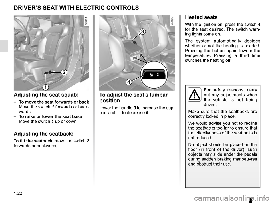
Adjusting the seat squab:
– To move the seat forwards or back
Move the switch 1 forwards or back- wards.
– To raise or lower the seat base
Move the switch 1 up or down.
Adjusting the seatback:
To tilt the seatback, move the switch 2
forwards or backwards.
Heated seats
With the ignition on, press the switch 4
for the seat desired. The switch warn-
ing lights come on.
The system automatically decides
whether or not the heating is needed.
Pressing the button again lowers the
temperature. Pressing a third time
switches the heating off.
1
2
To adjust the seat’s lumbar
position
Lower the handle 3 to increase the sup-
port and lift to decrease it.
3
4
Page 62 of 300
1.56
WARNING LIGHTS (3/6)
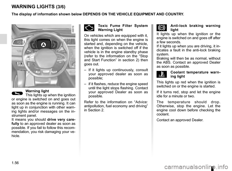
xAnti-lock braking warning
light
It lights up when the ignition or the
engine is switched on and goes off after
a few seconds.
If it lights up when you are driving, it in-
dicates a fault in the anti-lock braking
system.
Braking will then be as normal, without
the ABS. Contact an approved Dealer
as soon as possible.
ÔCoolant temperature warn-
ing light
This lights up red when the ignition is
switched on or the engine is started.
If it turns red, stop and let the engine
idle for a minute or two.
The temperature should drop.
Otherwise, stop the engine. Let the
engine cool down before checking the
coolant.
Contact an approved Dealer.
©Warning light
This lights up when the ignition
or engine is switched on and goes out
as soon as the engine is running. It can
light up in conjunction with other warn-
ing lights and/or messages on the in-
strument panel.
It means you should drive very care-
fully to an approved dealer as soon as
possible. If you fail to follow this recom-
mendation, you risk damaging your ve-
hicle.
ÄToxic Fume Filter System
Warning Light
On vehicles which are equipped with it,
this light comes on when the engine is
started and, depending on the vehicle,
when the ignition is switched off if the
vehicle is in the engine standby phase
(refer to the information on the “Stop
and Start Function” in section 2) then
goes out.
– If it lights up continuously, consult your approved dealer as soon as
possible;
– if it flashes, reduce the engine speed until the light stops flashing. Contact
your approved Dealer as soon as
possible.
Refer to the information on “Advice:
antipollution, fuel economy and driving”
in Section 2.
A
The display of information shown below DEPENDS ON THE VEHICLE EQUIPMENT \
AND COUNTRY.
Page 67 of 300
1.61
DISPLAYS AND INDICATORS (2/2)
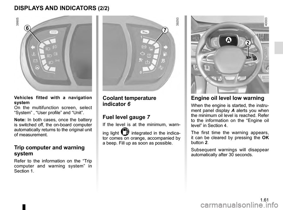
Engine oil level low warning
When the engine is started, the instru-
ment panel display A alerts you when
the minimum oil level is reached. Refer
to the information on the “Engine oil
level” in Section 4.
The first time the warning appears,
it can be cleared by pressing the OK
button 2.
Subsequent warnings will disappear
automatically after 30 seconds.
2A
Coolant temperature
indicator 6
Fuel level gauge 7
If the level is at the minimum, warn-
ing light
M integrated in the indica-
tor comes on orange, accompanied by
a beep. Fill up as soon as possible.
7
Vehicles fitted with a navigation
system
On the multifunction screen, select
“System” , “User profile” and “Unit”.
Note: In both cases, once the battery
is switched off, the on-board computer
automatically returns to the original unit
of measurement.
Trip computer and warning
system
Refer to the information on the “Trip
computer and warning system” in
Section 1.
6
Page 69 of 300
1.63
3
ON-BOARD COMPUTER: general information (2/2)
Interpreting some of the
values displayed after
resetting
The values showing average fuel con-
sumption and average speed will
become more stable and reliable the
further you have travelled since the last
time the Reset button was pressed.
The average fuel consumption may de-
crease when:
– the vehicle stops accelerating;
– the engine reaches its operating
temperature (if the engine was cold
when the reset key was pressed);
– when driving from an urban area
onto the open road.
Automatic resetting of the
journey parameters
Resetting occurs automatically when
the maximum value of any of the pa-
rameters is exceeded.
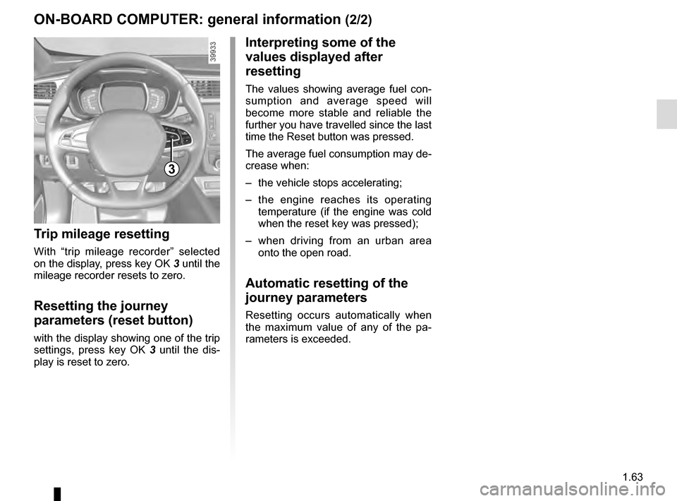
Trip mileage resetting
With “trip mileage recorder” selected
on the display, press key OK 3 until the
mileage recorder resets to zero.
Resetting the journey
parameters (reset button)
with the display showing one of the trip
settings, press key OK 3 until the dis-
play is reset to zero.
Page 81 of 300
1.75
CLOCK AND EXTERIOR TEMPERATURE
External temperature
indicator
Special note:
When the exterior temperature is - 3 °C
to + 3 °C, the °C characters flash (sig-
nalling a risk of ice on the road).
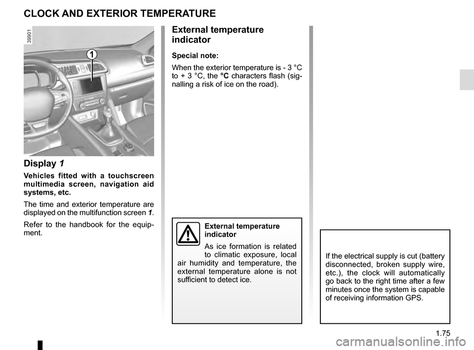
Display 1
Vehicles fitted with a touchscreen
multimedia screen, navigation aid
systems, etc.
The time and exterior temperature are
displayed on the multifunction screen 1.
Refer to the handbook for the equip-
ment.
External temperature
indicator
As ice formation is related
to climatic exposure, local
air humidity and temperature, the
external temperature alone is not
sufficient to detect ice.
1
If the electrical supply is cut (battery
disconnected, broken supply wire,
etc.), the clock will automatically
go back to the right time after a few
minutes once the system is capable
of receiving information GPS.