Page 163 of 258
3.27
Always position the heavi-
est items directly on the
floor. Use the lashing
points 1 on the boot floor, if
these are fitted to the vehicle. The
luggage should be loaded in such a
way that no items will be thrown for-
ward and strike the occupants if the
driver has to brake suddenly. Fasten
the rear seat belts, even if the seats
are not occupied.
TRANSPORTING OBJECTS IN THE LUGGAGE COMPARTMENT
Always position the objects transported
so that the largest surface is against:
– The rear bench seatback for normal loads (example A).
– The front seatbacks with the rear seatbacks folded down, as is the case
for maximum loads (example B).
If you have to place objects on the folded
seatback, it is necessary that you lower
the headrests before folding the seat-
back so that it can be folded as flat as
possible against the seat.
11
B
A
Page 164 of 258
3.28
Permissible nose weight, maxi-
mum permissible towing weight,
braked and unbraked: refer to
the information on “Weights” in
Section 6.
Choice and fitting of towing
equipment
Maximum weight of towing equip-
ment:
– 18 kg (5-door version);
– 18 kg (Utility version);
– 21.5 kg (Estate version).
For fitting and conditions of use,
refer to the equipment’s fitting ins-
tructions.
Please keep these instructions with
the rest of the vehicle documenta-
tion.
TRANSPORTING OBJECTS towbar
A
A: 697 mm (5-door version).
A: 697 mm (Utility version).
A: 948 mm (Estate version).
If the towbar ball obscures the regis-
tration plate or the rear fog lights, it
should be removed when not in use.
In all cases, comply with local leg-
islation.
Page 169 of 258

4.1
Section 4: Maintenance
Bonnet . . . . . . . . . . . . . . . . . . . . . . . . . . . . . . . . . . . . \
. . . . . . . . . . . . . . . . . . . . . . . . . . . . . . . . . . . . 4.2
Engine oil level: general information . . . . . . . . . . . . . . . . . . . . . . . . . . . . . . . . . . . .\
. . . . . . . . . . . . . 4.4
Engine oil level: topping up/filling . . . . . . . . . . . . . . . . . . . . . . . . . . . . . . . . . . . .\
. . . . . . . . . . . . . . . 4.5
Oil change . . . . . . . . . . . . . . . . . . . . . . . . . . . . . . . . . . . . \
. . . . . . . . . . . . . . . . . . . . . . . . . . . . . . . . . 4.6
Levels . . . . . . . . . . . . . . . . . . . . . . . . . . . . . . . . . . . .\
. . . . . . . . . . . . . . . . . . . . . . . . . . . . . . . . . . . . 4.7engine coolant . . . . . . . . . . . . . . . . . . . . . . . . . . . . . . . . . . . .\
. . . . . . . . . . . . . . . . . . . . . . . . 4.7
Brake fluid . . . . . . . . . . . . . . . . . . . . . . . . . . . . . . . . . . . .\
. . . . . . . . . . . . . . . . . . . . . . . . . . . 4.8
windscreen washer reservoir . . . . . . . . . . . . . . . . . . . . . . . . . . . . . . . . . . . . \
. . . . . . . . . . . . . 4.9
Filters . . . . . . . . . . . . . . . . . . . . . . . . . . . . . . . . . . . . \
. . . . . . . . . . . . . . . . . . . . . . . . . . . . . . . . . . . . . 4.9
Tyre pressure. . . . . . . . . . . . . . . . . . . . . . . . . . . . . . \
. . . . . . . . . . . . . . . . . . . . . . . . . . . . . . . . . . . . . 4.10
Battery . . . . . . . . . . . . . . . . . . . . . . . . . . . . . . . . . . . . \
. . . . . . . . . . . . . . . . . . . . . . . . . . . . . . . . . . . . 4.12
Bodywork maintenance . . . . . . . . . . . . . . . . . . . . . . . . . . . . . . . . . . . . \
. . . . . . . . . . . . . . . . . . . . . . . 4.13
Interior trim maintenance . . . . . . . . . . . . . . . . . . . . . . . . . . . . . . . . . . . . \
. . . . . . . . . . . . . . . . . . . . . . 4.15
Page 176 of 258

4.8
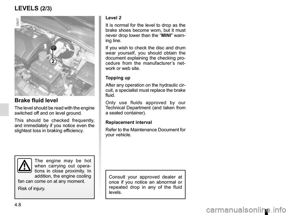
Level 2
It is normal for the level to drop as the
brake shoes become worn, but it must
never drop lower than the “MINI" warn-
ing line.
If you wish to check the disc and drum
wear yourself, you should obtain the
document explaining the checking pro-
cedure from the manufacturer’s net-
work or web site.
Topping up
After any operation on the hydraulic cir-
cuit, a specialist must replace the brake
fluid.
Only use fluids approved by our
Technical Department (and taken from
a sealed container).
Replacement interval
Refer to the Maintenance Document for
your vehicle.
Brake fluid level
The level should be read with the engine
switched off and on level ground.
This should be checked frequently,
and immediately if you notice even the
slightest loss in braking efficiency.
LEVELS (2/3)
2
The engine may be hot
when carrying out opera-
tions in close proximity. In
addition, the engine cooling
fan can come on at any moment.
Risk of injury.
Consult your approved dealer at
once if you notice an abnormal or
repeated drop in any of the fluid
levels.
Page 191 of 258

5.7
TYRE PRESSURE KIT (2/3)
Depending on the vehicle, in the event
of a puncture, use the kit located in the
boot or underneath the luggage com-
partment carpet.
Vehicle fitted with a tyre pressure
loss warning system
If under-inflated (puncture, low pres-
sure, etc.), the warning light
� on
the instrument panel comes on. See
“Tyre pressure loss warning” in
Section 2.
With the engine running and the
parking brake applied,
– unroll the hose from the container;
– connect the compressor hose 3 to
the container’s inlet 8;
– depending on the vehicle, connect the container 8 to the compressor
from the container recess 7;
– unscrew the valve cap on the rele- vant wheel and screw on the con-
tainer’s inflation adapter 1;
– disconnect any accessories previ- ously connected to the vehicle’s ac-
cessories sockets;
– adapter 2 must be connected to the
vehicle accessories socket;
45
1
Before using this kit, park
the vehicle at a sufficient
distance from traffic, switch
on the hazard warning
lights, apply the handbrake, ask all
passengers to leave the vehicle and
keep them away from traffic.
8
If the vehicle is parked on
the hard shoulder, you must
warn other road users of
your vehicle’s presence
with a warning triangle or with other
devices as per the legislation apply-
ing to the country you are in.
– press switch 4 to inflate the tyre to
the recommended pressure (please
refer to the information in the section
on “Tyre pressure”);
– after a maximum of 15 minutes, stop inflating and read the pressure (on
pressure gauge 5).
Note: while the container is empty-
ing (approximately 30 seconds), the
pressure gauge 5 will briefly indicate
a pressure of up to 6 bar. The pres-
sure will then drop.
– adjust the pressure: to increase it, continue inflation with the kit; to
reduce it, press button 6.
2
3
7
6
Page 195 of 258

5.11
Continue to crank the jack so that the
baseplate is correctly positioned (it
should be underneath the vehicle and
aligned with the jack head).
Turn it a few times to lift the wheel off
the ground.
Switch on the hazard warn-
ing lights.
Keep the vehicle away from
traffic and on a level surface
where it will not slip.
Apply the parking brake and engage
a gear (first or reverse, or P for auto-
matic transmissions).
Ask all the passengers to leave the
vehicle and keep them away from
traffic.
CHANGING A WHEEL (1/2)
2
1
Vehicles equipped with a jack
and wheelbrace
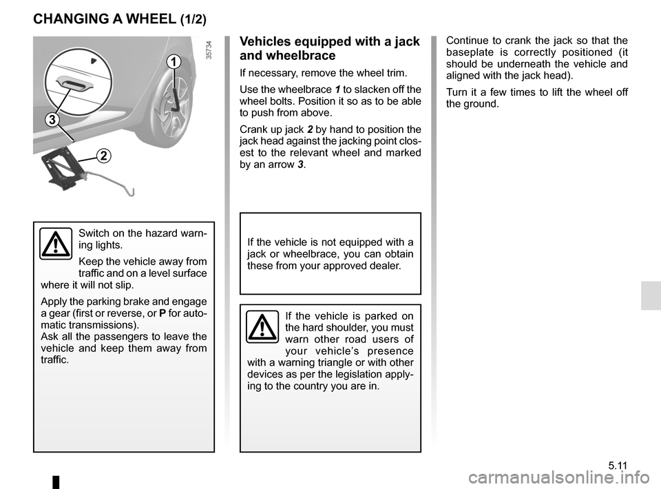
If necessary, remove the wheel trim.
Use the wheelbrace 1 to slacken off the
wheel bolts. Position it so as to be able
to push from above.
Crank up jack 2 by hand to position the
jack head against the jacking point clos-
est to the relevant wheel and marked
by an arrow 3.
If the vehicle is not equipped with a
jack or wheelbrace, you can obtain
these from your approved dealer.
3
If the vehicle is parked on
the hard shoulder, you must
warn other road users of
your vehicle’s presence
with a warning triangle or with other
devices as per the legislation apply-
ing to the country you are in.
Page 204 of 258
5.20
To release the light unit, start by moving
the exterior edge away to a suffi-
cient extent (movement A) to release
clip 3, then pull the light unit backwards
(movement B).
Remove the bulb holder by carefully
releasing clips 4, lightly raise the bulb
holder and then release clip 2.
Change the bulb.
The bulbs are under pres-
sure and can break when
replaced.
Risk of injury.
Refit the bulb holder and push the unit
in fully until it locks in place.
Check that the light is properly locked
in position.
Tighten screws 1.
5 Side light and brake light
Bulb type: P21/5W.
6 Direction indicator lights
Bulb type: PY21.Five-door version
Side lights/brake and direction
indicator lights
Open the boot lid and remove screws 1.
REAR AND SIDE LIGHTS: changing bulbs (1/4)
5
6
1
4
2
3
To comply with current legislation, or
as a precaution, you can obtain an
emergency kit from your approved
dealer containing a set of spare
bulbs and fuses.
B
A
Page 205 of 258
5.21
REAR AND SIDE LIGHTS: changing bulbs (2/4)
Estate version
Side lights/brake and direction
indicator lights
Unclip the cover to access nut 7.
Unscrew nut 7.
Unscrew screw 8.
Pull the light unit backwards (move-
ment A). Remove the bulb holder by carefully re-
leasing clips
9, and gently pull the bulb
holder.
Change the bulb.
Refit the bulb holder and push the unit
as far as it will go, until it locks into
place.
Check that the light is properly locked
in position.
Tighten the screw 8 and nut 7.
Clip the cover in place.
10 Side light and brake light
Bulb type: P21/5W.
11 Direction indicator lights
Bulb type: PY21.
7
8
9
1011
A