Page 189 of 258
5.5
NB: if the tool kit does not lock in place,
check the tightness of nut 3 and the
correct positioning of handle 4.
Special features
The emergency spare wheel holder
should always be present when you are
driving even when the wheel itself is not
present: risk of water entering the vehi-
cle.
If you have to release it when it is not
holding a wheel, push the centre of the
wheel holder towards the ground while
pressing handle 4.
To lock the system
– Press nut 3, screwing it on fully until
it locks in place. Several turns will
be necessary. This operation is es-
sential to ensure that the wheel is
secure;
– return handle 4 to its original posi-
tion;
– clip the tool kit;
– replace the cover, then lower it and replace the luggage compartment
carpet.
PUNCTURE, EMERGENCY SPARE WHEEL (4/4)
The system should only
be used with the original
vehicle wheels or identical
wheels.
It is essential to lock the nut
so that the wheel is held se-
curely.
4
3
Page 192 of 258

5.8
TYRE PRESSURE KIT (3/3)
If a minimum pressure of 1.8 bar is
not reached after 15 minutes, repair
is not possible; do not drive the ve-
hicle but contact an approved dealer.
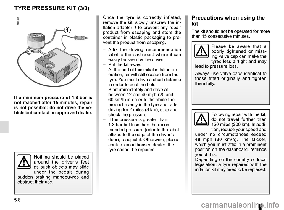
Once the tyre is correctly inflated,
remove the kit: slowly unscrew the in-
flation adapter 1 to prevent any repair
product from escaping and store the
container in plastic packaging to pre-
vent the product from escaping.
– Affix the driving recommendation label to the dashboard where it can
easily be seen by the driver;
– Put the kit away.
– At the end of this initial inflation op- eration, air will still escape from the
tyre. You must drive a short distance
in order to seal the hole.
– Start immediately and drive at between 12 and 40 mph (20 and
60 km/h) in order to distribute the
product evenly in the tyre and, after
driving for 2 miles (3 km), stop and
check the pressure.
– If the pressure is greater than 1.3 bar but less than the recom-
mended pressure (refer to the label
affixed to the edge of the driver’s
door), readjust it. Otherwise, please
contact an authorised dealer: the
tyre cannot be repaired.Precautions when using the
kit
The kit should not be operated for more
than 15 consecutive minutes.
Nothing should be placed
around the driver’s feet
as such objects may slide
under the pedals during
sudden braking manoeuvres and
obstruct their use.
1
Please be aware that a
poorly tightened or miss-
ing valve cap can make the
tyres less airtight and may
lead to pressure loss.
Always use valve caps identical to
those fitted originally and tighten
them fully.
Following repair with the kit,
do not travel further than
120 miles (200 km). In addi-
tion, reduce your speed and
under no circumstances exceed
48 mph (80 km/h). The sticker,
which you must affix in a prominent
position on the dashboard, reminds
you of this.
Depending on the country or local
legislation, a tyre repaired with the
inflation kit may need to be replaced.
Page 193 of 258

5.9
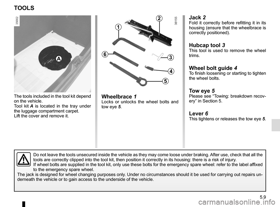
Jack 2Fold it correctly before refitting it in its
housing (ensure that the wheelbrace is
correctly positioned).
Hubcap tool 3
This tool is used to remove the wheel
trims.
Wheel bolt guide 4To finish loosening or starting to tighten
the wheel bolts.
Tow eye 5Please see “Towing: breakdown recov-
ery” in Section 5.
Lever 6This tightens or releases the tow eye 5.
Wheelbrace 1Locks or unlocks the wheel bolts and
tow eye 5.
The tools included in the tool kit depend
on the vehicle.
Tool kit
A is located in the tray under
the luggage compartment carpet.
Lift the cover and remove it.
TOOLS
A
Do not leave the tools unsecured inside the vehicle as they may come loo\
se under braking. After use, check that all the
tools are correctly clipped into the tool kit, then position it correctl\
y in its housing: there is a risk of injury.
If wheel bolts are supplied in the tool kit, only use these bolts for th\
e emergency spare wheel: refer to the label affixed
to the emergency spare wheel.
The jack is designed for wheel changing purposes only. Under no circumstances should it be used for carrying out repairs un-
derneath the vehicle or to gain access to the underside of the vehicle.
2
1
3
5
4
6
Page 194 of 258
5.10
Remove the wheel trim using hubcap
tool 1 (located in the tool kit) by en-
gaging the hook in the opening near
valve 2.
To refit it, align it with valve 2. Push the
retaining hooks in fully, starting with
side A near the valve, followed by B
and C, finishing at D opposite the valve.
WHEEL TRIMS - WHEEL
Do not leave the tools un-
secured inside the vehicle
as they may come loose
under braking. After use,
check that all the tools are correctly
clipped into the tool kit, then posi-
tion it correctly in its housing: risk of
injury.
1
2
A
B
D
C
Page 196 of 258

5.12
If you have a puncture, re-
place the wheel as soon as
possible.
A tyre which has been punc-
tured should always be inspected
(and repaired, where possible) by a
specialist.
CHANGING A WHEEL (2/2)
Undo the bolts and take off the wheel.
Fit the emergency spare wheel on the
central hub and turn it to locate the
mounting holes in the wheel and the
hub.
Tighten the bolts, checking that the
wheel is correctly positioned on its hub.
Lower the jack.
With the wheel on the ground, tighten
the bolts fully and have the tightness of
the bolts checked and the emergency
spare wheel pressure checked as soon
as possible.
Do not leave the tools un-
secured inside the vehicle
as they may come loose
under braking. After use,
check that all the tools are correctly
clipped into the tool kit, then posi-
tion it correctly in its housing: risk of
injury.
If wheel bolts are supplied in the
tool kit, only use these bolts for the
emergency spare wheel: refer to the
label affixed to the emergency spare
wheel.
The jack is designed for wheel
changing purposes only. Under no
circumstances should it be used for
carrying out repairs underneath the
vehicle or to gain access to the un-
derside of the vehicle.
Vehicle fitted with a tyre pressure
loss warning system
If under-inflated (puncture, low pres-
sure, etc.), the warning light
� on
the instrument panel comes on. See
“Tyre pressure loss warning” in
Section 2.
Page 200 of 258

5.16
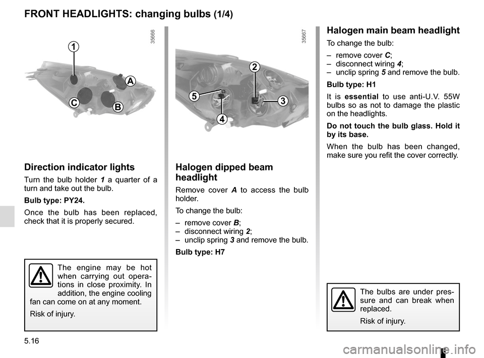
Halogen dipped beam
headlight
Remove cover A to access the bulb
holder.
To change the bulb:
– remove cover B;
– disconnect wiring 2;
– unclip spring 3 and remove the bulb.
Bulb type: H7
FRONT HEADLIGHTS: changing bulbs (1/4)
The engine may be hot
when carrying out opera-
tions in close proximity. In
addition, the engine cooling
fan can come on at any moment.
Risk of injury.
B
Halogen main beam headlight
To change the bulb:
– remove cover C;
– disconnect wiring 4;
– unclip spring 5 and remove the bulb.
Bulb type: H1
It is essential to use anti-U.V. 55W
bulbs so as not to damage the plastic
on the headlights.
Do not touch the bulb glass. Hold it
by its base.
When the bulb has been changed,
make sure you refit the cover correctly.
C
2
4
53
Direction indicator lights
Turn the bulb holder 1 a quarter of a
turn and take out the bulb.
Bulb type: PY24.
Once the bulb has been replaced,
check that it is properly secured.
1
A
The bulbs are under pres-
sure and can break when
replaced.
Risk of injury.
Page 215 of 258
5.31
Number Allocation
18 Radio and multimedia,
diagnostic socket
19 Power-assisted steering
20 GPL
21 Airbag,
electric locking of steering
column
22 Injection,
starting,
fuel pump
23 Brake switch,
rear screen wiper,
passenger compartment
ECU
FUSES (5/5)
Number Allocation
24 Daytime running lights
25 Electric headlight beam
adjustment,
rear screen,
heating,
parking sensor,
cruise control,
radio,
heated seat,
seat belt warning
26 Automatic gearbox
27 Reversing light,
rear screen wiper,
passenger compartment
ECU,
Automatic gearbox
28 Instrument panel
29 Steering column controls,
AlarmNumber Allocation
30 Air conditioning,
steering column controls,
energy ECU
31 Wipers,
rear reversing lights,
energy ECU
32 Central locking of opening
elements
33 Direction indicator lights
34 Passenger compartment
ECU,
hands-free access
35 Interior lighting,
electric windows,
air conditioning,
electric door mirrors,
brake lights,
ABS,
passenger compartment
ECU