Page 187 of 364

185
5008_en_Chap08_conduite_ed01-2015
Visual and audible front and rear parking sensors
System consisting of four proximity sensors,
installed in the front and/or rear bumper.
It detects any obstacle (person, vehicle, tree,
barrier...) located behind the vehicle, however,
it will not be able to detect obstacles located
immediately below the bumper.The parking sensors are switched on
:
- b y engaging reverse gear,
-
a
t a speed below 6 mph (10 km/h) in
forward gear.
This is accompanied by an audible signal
and display of the vehicle in the multifunction
screen. The proximity information is indicated by:
-
a n audible signal which becomes more
rapid as the vehicle approaches the
obstacle,
-
a
n image in the multifunction screen, with
blocks which move closer to the vehicle.
The obstacle is located in relation to the
emission of the audible signal by the speakers;
front or rear and right or left.
When the distance between the vehicle
and the obstacle is less than approximately
thirty
centimetres, the audible signal
becomes continuous and/or the "Danger"
symbol appears, depending on the version of
multifunction screen.
An object, such as a stake, a roadworks
cone or any other similar object may be
detected at the start of the manoeuvre
but may no longer be detected when the
vehicle moves nearer to it.
8
Driving
Page 193 of 364

191
5008_en_Chap09_verifications_ed01-2015
Fuel tank
Low fuel levelRefuelling
When the low fuel level is reached,
this warning lamp comes on in the
instrument panel, accompanied by
an audible signal and a message in
the multifunction screen. When the lamp first
comes on, there is approximately 6 litres of
fuel remaining.
Until sufficient fuel has been added, this
warning lamp appears every time the ignition
is switched on, accompanied by an audible
signal and a message. When driving, this
audible signal and message are repeated with
increasing frequency, as the fuel level drops
towards "0" .
Capacity of the tank: approximately 60 litres.
The key cannot be removed from the
lock until the cap is put back on the
tank.
Opening the cap may trigger an inrush
of air. This vacuum, which is completely
normal, is caused by the sealing of the
fuel system.
You must refuel to avoid running out of
fuel.
If you run out of fuel (Diesel), refer also
to the "Checks" section. A label affixed to the inside of the filler flap
reminds you of the type of fuel to be used
according to your engine.
More than 5 litres of fuel must be added in
order to be registered by the fuel gauge.
9
Checks
Page 212 of 364

210
5008_en_Chap09_verifications_ed01-2015
Never store bottles of AdBlue® in your
vehicle.
Recommendations on storage
AdBlue® freezes at about -11°C and
deteriorates above 25°C. It is recommended
that bottles be stored in a cool area and
protected from direct sunlight.
Under these conditions, the additive can be
kept for at least a year.
If the additive has frozen, it can be used once it
has completely thawed out.
Procedure
Before topping-up, ensure that the vehicle is
parked on a flat and level sur face.
In wintry conditions, ensure that the
temperature of the vehicle is above -11°C.
Otherwise the AdBlue
® may be frozen and
so cannot be poured into its tank. Park your
vehicle in a warmer area for a few hours to
allow the top-up to be carried out.
F
S
witch off the ignition and remove the key. F
F
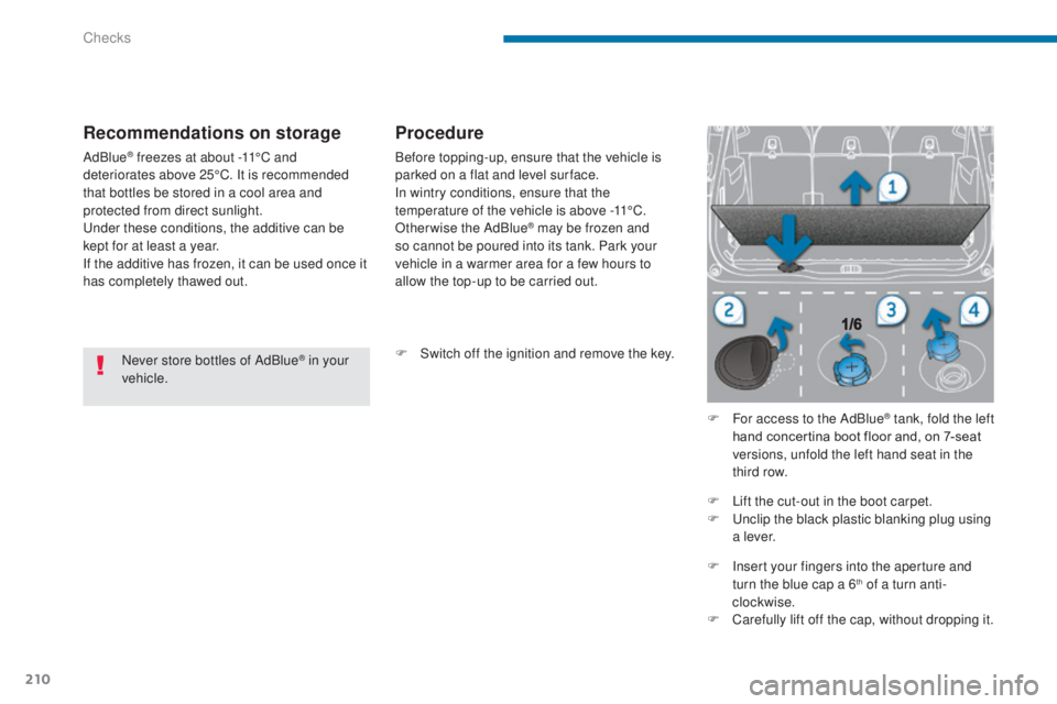
or access to the AdBlue
® tank, fold the left
hand concertina boot floor and, on 7-seat
versions, unfold the left hand seat in the
third row.
F
L
ift the cut-out in the boot carpet.
F
U
nclip the black plastic blanking plug using
a l eve r.
F
I
nsert your fingers into the aperture and
turn the blue cap a 6
th of a turn anti-
clockwise.
F
C
arefully lift off the cap, without dropping it.
Checks
Page 213 of 364

211
5008_en_Chap09_verifications_ed01-2015
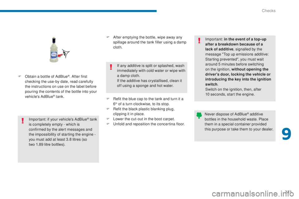
F Obtain a bottle of AdBlue®. After first
checking the use-by date, read carefully
the instructions on use on the label before
pouring the contents of the bottle into your
vehicle's AdBlue
® tank.
Important: if your vehicle's AdBlue
® tank
i
s completely empty - which is
confirmed by the alert messages and
the impossibility of starting the engine
-
you must add at least 3.8 litres (so
two
1.89 litre bottles). F
A
fter emptying the bottle, wipe away any
spillage around the tank filler using a damp
cloth.
If any additive is split or splashed, wash
immediately with cold water or wipe with
a damp cloth.
If the additive has crystallised, clean it
off using a sponge and hot water.
F
R
efit the blue cap to the tank and turn it a
6
th of a turn clockwise, to its stop.
F
R
efit the black plastic blanking plug,
clipping it in place.
F
L
ower the cut-out in the boot carpet.
F
U
nfold and reposition the concertina floor. Important: in the event of a top-up
after a breakdown because of a
lack of additive
, signalled by the
message "Top up emissions additive:
Starting prevented", you must wait
around 5 minutes before switching
on the ignition, without opening the
driver's door, locking the vehicle or
introducing the key into the ignition
switch .
Switch on the ignition, then, after
10 seconds, start the engine.
Never dispose of AdBlue
® additive
bottles in the household waste. Place
them in a special container provided
this purpose or take them to your dealer.
9
Checks
Page 226 of 364
224
5008_en_Chap10_infos-pratiques_ed01-2015
F Detach the wheel/box assembly from the rear of the vehicle.
F
S
traighten the wheel for acces to the tool
box.
F
R
emove the link piece from the lid of the
tool box, as shown in the illustration.
F
P
ass the link piece through the hub of the
wheel.
F
P
lace the extension 7 onto the spare wheel
carrier drive nut.
F
F
it the wheelbrace 6 to the end of the
extension 7 .
F
T
urn the assembly fully clockwise to
unwind the carrier cable, until the spare
wheel is resting flat on the ground. When the spare wheel is fitted in place
of a wheel with a punctured tyre, it is
essential to return the carrier and tool
box to their position under the vehicle,
before moving off.
Refer to the "Putting the carrier and
spare wheel back in place" section.
Practical information
Page 227 of 364
225
5008_en_Chap10_infos-pratiques_ed01-2015
This procedure is to be carried out with or
without the spare wheel. Without the spare
wheel, skip steps a and d.
Only a "space-saver" type can be secured
under the vehicle in the carrier.
F
S
tore the tools used in the box and close
the cover.
F
P
osition the box on the ground close to the
back of the vehicle.
F
S
traighten the wheel and pass the link
piece through the hub of the wheel.
F
I
nsert the link piece through the aperture in
the tool box lid, as shown in the illustration.
F
C
entre the spare wheel on the tool box. F
T
ighten fully and check that the wheel is
horizontally flush against the floor.
F
P
lace the assembly of wheel and tool box
under the rear of the vehicle.
F R aise the wheel and tool box by turning the
carrier drive nut anticlockwise using the
wheelbrace 6 and the extension 7 .
Putting the carrier and spare wheel back in place
10
Practical information
Page 228 of 364

226
5008_en_Chap10_infos-pratiques_ed01-2015
Removing a wheel
F Depending on equipment, clip the tool 4 to the finisher cap on each wheel bolt with
alloy wheels to remove them.
F
D
epending on equipment, slacken the
security bolt using the socket 3 fitted to the
wheelbrace 6 .
F
S
lacken the other bolts using the
wheelbrace 6 .
Parking the vehicle
Immobilise the vehicle where it does not
block traffic: the ground must be level,
stable and non-slippery ground.
Apply the parking brake unless it has
been programmed to automatic mode.
Switch off the ignition.
With a manual gearbox, engage first
gear to block the wheels.
With an electronic gearbox, place the
lever in position R to block the wheels.
With an automatic gearbox, place the
lever in position P to block the wheels.
Check that the braking warning lamp
and the P warning lamp in the parking
brake control come on.
If necessary, place a chock under the
wheel diagonally opposite the wheel to
be changed.
The occupants must get out of the
vehicle and wait where they are safe.
Never go underneath a vehicle raised
using a jack; use an axle stand. F
P
osition the foot of the jack 8 on the
ground and ensure that it is directly below
one of the front A or rear B jacking points
provided on the underbody, whichever is
closest to the wheel to be changed.
Wheel with wheel trim
When removing the wheel , first
remove the wheel trim using the
wheelbrace 6 by pulling at the valve
cut-out.
When refitting the wheel , refit the
wheel trim by placing its cut-out at the
valve, and press round its edge with the
palm of your hand.
Practical information
Page 241 of 364
239
5008_en_Chap10_infos-pratiques_ed01-2015
Access to the fuses
F Refer to the paragraph "Access to the to o ls". Fuse
N° Rating
(A) Functions
F8 20Audio equipment, audio/telephone, CD changer, multifunction
screen, tyre under-inflation detection, alarm siren, alarm control
unit, telematic unit.
F9 30Front 12 V socket, cigarette lighter, rear 12 V socket.
F10 15Steering mounted controls.
F11 15Low current ignition switch.
F12 15Trailer presence, rain / sunshine sensor, supply for fuses F32,
F34, F35.
F13 5Engine fusebox, airbag control unit.
F14 15Instrument panel, instrument panel screen, supply for fuse F33.
F15 30Locking and deadlocking.
F17 40Heated rear screen, supply for fuse F30.
10
Practical information