Page 416 of 478
 cover�Acounter-
clockwise to access the (high beam) bulb
socket
�C. Rotate the bulb socket�Ccoun-
terclockwise and remove bulb.
2. Rotate the (low beam) cover
�B(if so
equipp")
1. Rotate the (high beam) cover�Acounter-
clockwise to access the (high beam) bulb
socket
�C. Rotate the bulb socket�Ccoun-
terclockwise and remove bulb.
2. Rotate the (low beam) cover
�B(if so
equipped) counterclockwise to access the
(low beam) bulb socket
�D(if so equipped) .
Rotate the bulb socket
�D(if so equipped)
counterclockwise and remove bulb.
3. Rotate the side marker bulb socket
�Ecoun-
terclockwise and remove bulb.
4. Rotate the turn signal bulb socket
�Fcoun-
terclockwise and remove bulb
�G. Reverse instructions to install bulbs and replace
fender protector.
WARNING
Do not touch bulb by hand while it is lit or
right after being turned off. Burning may
result.
CAUTION
• Do not touch glass surface of the bulb
with bare hands or allow oil or grease to
get on it to prevent damage to bulb.
• Do not leave the bulb out of the lamp
reflector for a long time because dust,
moisture, smoke, etc. may affect the per-
formance of the lamp.
• Fog may temporarily form inside the lens
of the exterior lights in the rain or in a car
wash. A temperature difference between
the inside and the outside of the lens
causes the fog. This is not a malfunction. If
large drops of water collect inside the
lens, it is recommended that you visit a
NISSAN dealer for servicing.
Replacing the LED headlight bulb (if
so equipped)
If LED headlight bulb replacement is required, it is
recommended that you visit a NISSAN dealer for
this service.
TURN SIGNAL BULB
To replace the turn signal bulb follow the instruc-
tions listed in the “Replacing the halogen head-
light bulb” found in this section.
FOG LIGHTS (if so equipped)
Type B (if so equipped)
LDI2981
Maintenance and do-it-yourself8-29
Page 417 of 478
Replacing the fog light bulb
CAUTION
●High pressure halogen gas is sealed
inside the halogen bulb. The bulb may
break if the glass envelope is scratched
or the bulb is dropped.
● When handling the bulb, do not touch
the glass envelope.
● Use the same number and wattage as
originally installed as shown in the
chart.
● Do not leave the bulb out of the fog light
for a long period of time as dust, mois-
ture and smoke may enter the fog light
body and affect the performance of the
fog light.
1. Disconnect the negative battery cable.
2. Access to the fog light is in front of and behind the front tire and the fascia.
3. Remove the fasteners
�A; carefully pull back
the front fender protector.
4. Rotate the bulb
�Bcounterclockwise and
pull out to remove.
LDI2935
8-30Maintenance and do-it-yourself
Page 418 of 478

5. Remove by pulling straight off the fog light.Do not shake or rotate the bulb when remov-
ing it.
6. Install the new bulb in the reverse order of removal.EXTERIOR AND INTERIOR LIGHTS
Item Wattage (W)Bulb No.
Headlight assembly (Type A) (if so equipped) Low/Daytime running (Canada only) 55H11
High 65H9
Turn/Park 27/83157 AK
Side marker 5W5W
Headlight assembly (Type B) (if so equipped) Low/Daytime running (Canada only)* ——
High 65H9
Turn/Park 27/83157 AK
Park ——
Side marker 5W5W
Front fog light (if so equipped) 55H11
Door mirror turn signal light (if so equipped)* ——
Vanity mirror light (if so equipped)* ——
Map lights* ——
Room light 8—
Trunk light* 3.4158
High-mounted stop light* Inside (if so equipped) ——
Spoiler (if so equipped) ——
Rear combination light* Turn 21WY21W
Ta i l ——
Stop/Tail 21/5W21/5W
Backup (reversing) 16W16W
Side marker ——
License plate light* 5W5W
Always check with the Parts Department at a NISSAN dealer for the latest parts information.
* It is recommended that you visit a NISSAN dealer for replacement.
Maintenance and do-it-yourself8-31
Page 419 of 478
1. Map light
2. Room light
3. Door mirror turn signal light (if soequipped)
4. Headlight assembly
5. Fog light (if so equipped)
6. High-mount stop light
7. Trunk light
8. License plate light
9. Rear combination light
Replacement procedures
All other lights are either type A, B, C or D. When
replacing a bulb, first remove the lens, lamp
and/or cover.
Indicates bulb removal
Indicates bulb installationLDI2936
WDI0263
8-32Maintenance and do-it-yourself
Page 420 of 478

This vehicle is equipped with the Tire")
If you have a flat tire, refer to “Flat tire” in
the “In case of emergency” section of this
manual.
TIRE PRESSURE
Tire Pressure Monitoring System
(TPMS)
This vehicle is equipped with the Tire
Pressure Monitoring System (TPMS) . It
monitors tire pressure of all tires except
the spare. When the low tire pressure
warning light is lit and the CHECK TIRE
PRES warning is displayed in the odom-
eter, one or more of your tires is signifi-
cantly under-inflated.
The TPMS will activate only when the
vehicle is driven at speeds above 16 mph
(25 km/h). Also, this system may not de-
tect a sudden drop in tire pressure (for
example a flat tire while driving) .
For additional information, refer to “Low
tire pressure warning light” in the “Instru-
ments and controls” section, “Tire Pres-
sure Monitoring System (TPMS)” in the“Starting and driving” section, and “Flat
tire” in the “In case of emergency” section
of this manual.
Tire inflation pressure
Check the tire pressures (including the
spare) often and always prior to long dis-
tance trips. The recommended tire pres-
sure specifications are shown on the
F.M.V.S.S./C.M.V.S.S. certification label
or the Tire and Loading Information label
under the “Cold Tire Pressure” heading.
The Tire and Loading Information label is
affixed to the driver side center pillar. Tire
pressures should be checked regularly
because:
● Most tires naturally lose air over time.
● Tires can lose air suddenly when
driven over potholes or other objects
or if the vehicle strikes a curb while
parking. The tire pressures should be checked
when the tires are cold. The tires are
considered COLD after the vehicle has
been parked for 3 or more hours, or driven
less than 1 mile (1.6 km) at moderate
speeds.
The TPMS with Easy Fill Tire Alert (if so
equipped) provides visual and audible
signals outside the vehicle for inflating
tires to the recommended COLD tire
pressure. For additional information, refer
to “TPMS with Easy Fill Tire Alert” in the
“Starting and driving” section of this
manual.
WHEELS AND TIRES
Maintenance and do-it-yourself8-33
Page 421 of 478

Incorrect tire pressure, including un-
der inflation, may adversely affect
tire life and vehicle handling.
WARNING
● Improperly inflated tires can fail
suddenly and cause an accident.
● The Gross Vehicle Weight Rating
(GVWR) is located on the
F.M.V.S.S./C.M.V.S.S. certifica-
tion label. The vehicle weight ca-
pacity is indicated on the Tire and
Loading Information label. Do
not load your vehicle beyond this
capacity. Overloading your ve-
hicle may result in reduced tire
life, unsafe operating conditions
due to premature tire failure, or
unfavorable handling character-
istics and could also lead to a
serious accident. Loading beyond
the specified capacity may also
result in failure of other vehicle
components. ●
Before taking a long trip, or
whenever you heavily load your
vehicle, use a tire pressure gauge
to ensure that the tire pressures
are at the specified level.
● For additional information re-
garding tires, refer to “Important
Tire Safety Information” (US) or
“Tire Safety Information”
(Canada) in the Warranty Infor-
mation Booklet.
8-34
Maintenance and do-it-yourself
Page 422 of 478
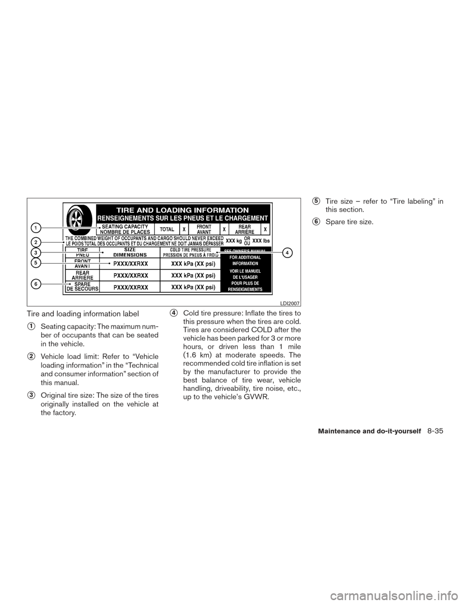
Tire and loading information label
�1Seating capacity: The maximum num-
ber of occupants that can be seated
in the vehicle.
�2Vehicle load limit: Refer to “Vehicle
loading information” in the “Technical
and consumer information” section of
this manual.
�3Original tire size: The size of the tires
originally installed on the vehicle at
the factory.
�4Cold tire pressure: Inflate the tires to
this pressure when the tires are cold.
Tires are considered COLD after the
vehicle has been parked for 3 or more
hours, or driven less than 1 mile
(1.6 km) at moderate speeds. The
recommended cold tire inflation is set
by the manufacturer to provide the
best balance of tire wear, vehicle
handling, driveability, tire noise, etc.,
up to the vehicle’s GVWR.
�5Tire size – refer to “Tire labeling” in
this section.
�6Spare tire size.
LDI2007
Maintenance and do-it-yourself8-35
Page 423 of 478

Checking tire pressure
1. Remove the valve stem cap from thetire.
2. Press the pressure gauge squarely onto the valve stem. Do not press too
hard or force the valve stem side-
ways, or air will escape. If the hissing
sound of air escaping from the tire is
heard while checking the pressure,
reposition the gauge to eliminate this
leakage.
3. Remove the gauge. 4. Read the tire pressure on the gauge
stem and compare to the specifica-
tion shown on the Tire and Loading
Information label.
5. Add air to the tire as needed. If too much air is added, press the core of
the valve stem briefly with the tip of
the gauge stem to release pressure.
Recheck the pressure and add or
release air as needed.
6. Install the valve stem cap.
7. Check the pressure of all other tires, including the spare.Grades: S, SV, SR, SL
Size Cold Tire Inflation
Pressure
Front Original Tire:
205/50R17
P205/55R16 230 kPa, 33 PSI
Rear Original Tire:
205/50R17
P205/55R16 230 kPa, 33 PSI
Grades: S, SV, SR, SL
Spare Tire:
T125/70D16 420 kPa, 60 PSI
Grades: FE + S
Size Cold Tire Inflation
Pressure
Front Original Tire:
P205/55R16 250 kPa, 36 PSI
Rear Original Tire:
P205/55R16 250 kPa, 36 PSI
Spare Tire:
T125/70D16 420 kPa, 60 PSI
LDI0393
8-36Maintenance and do-it-yourself


4. Headlight assembly
5. Fog light (if so equipped)
6. High-mount stop light
7. Trunk light
8. License plate light
9. Rear c")