Page 209 of 338

When the above conditions are corrected, the BSW
system will resume automatically.
BSW AUTOMATIC DEACTIVATION
When dirt, rain or snow accumulates on the rear
camera, or the windscreen in front of the multi-sens-
ing camera, the BSW system will be turned off auto-
matically. The BSW light will blink.
Action to take:
If the message appears, park the vehicle in a safe
place, clean the camera unit and/or windscreen with
a soft cloth. Then turn off and restart the engine.
BSW MALFUNCTION
If the BSW system malfunctions, it will be turned off
automatically and the BSW light (orange) will illumi-
nate.
Action to take:
Stop the vehicle in a safe location, turn off and re-
start the engine. If the BSW light (orange) continues
to illuminate, have the BSW system checked by a
NISSAN dealer or qualified workshop.
BSW CAMERA UNIT MAINTENANCE
The rear camera unitj1 for the BSW system is
located above the rear number plate and it has a
automatic washer and blower for cleaning the lens.
To maintain the proper operation of the BSW sys-
tem and prevent a system malfunction be sure to
observe the following:
•Always keep the camera unit clean. Be careful
not to damage the nozzle of automatic washer
and blower.
•Do not attach “number plate accessories” that
reflect light.
•Do not strike or damage the areas around the
camera unit.The Lane Departure Warning (LDW) system alerts
the driver when the vehicle is travelling close to ei-
ther the left or the right of a travelling lane.
The LDW system uses the multi-sensing front cam-
era unit situated in front of the interior rear view mir-
ror
j1.
WARNING
•The LDW system is only a warning device to
help inform the driver of a potential unin-
tended lane departure. It will not steer the
vehicle or prevent loss of control. It is the driv-
er’s responsibility to stay alert, drive safely,
keep the vehicle in the travelling lane, and be
in control of the vehicle at all times.
•The camera units may not function properly
under the following conditions:
– When towing a trailer.
NAA1429
NSD522
LANE DEPARTURE WARNING
(LDW) SYSTEM (where fitted)
Starting and driving5-33
Page 210 of 338

– When strong light enters the camera unit.
(for example, light directly shines on the
front or rear of the vehicle at sunrise or
sunset.)
– When ambient brightness changes sud-
denly. (for example, when the vehicle en-
ters or exits a tunnel or passes under a
bridge.)
•Excessive noise (for example, audio system
volume, open vehicle window) will interfere
with the chime sound, and it may not be heard.
LDW SYSTEM OPERATION
The LDW system operates above approximately 60
km/h (37 MPH).
When the vehicle approaches either the left or the
right of the travelling lane, the LDW system will
chime and the LDW light (orange) in the vehicle
information display will blink to alert the driver.
The LDW system is not designed to operate under
the following conditions:
•When you operate the lane change signal and
change travelling lanes in the direction of the sig-
nal. (The LDW system will become operable
again approximately 2 seconds after the lane
change signal is turned off.)
•When the vehicle speed is less than approxi-
mately 60 km/h (37 MPH).
Turning on or off the LDW system
Turning the LDW system on or of is done using the
[Settings] menu in the vehicle information display.
For details, see “Vehicle information display” in the
“2. Instruments and controls” section.
In the [Settings] menu, select the [Driver Assistance]
key.
Then select [Driving Aids]. Select [Lane Departure
Warning] key by pressing.
A tick mark next to [Lane Departure Warning] indi-
cates that the system is turned on.
SYSTEM ON:
The LDW light in the vehicle information display will
light up.
SYSTEM OFF:
The LDW light in the vehicle information display will
turn off.
WARNING
•The camera unit may not be able to detect
properly under the following conditions:
– On roads where there are multiple parallel
lane markers; lane markers that are faded
NAA1438
NAA1428LDW light
5-34Starting and driving
Page 211 of 338

or not painted clearly; yellow painted lane
markers; non-standard lane markers; or
lane markers covered with water, dirt,
snow, etc.
– On roads where the discontinued lane
markers are still detectable.
– On roads where there are sharp curves.
– On roads where there are sharply contrast-
ing objects, such as shadows, snow, wa-
ter, wheel ruts, seams or lines remaining
after road repairs. (The LDW system could
detect these items as lane markers.)
– On roads where the travelling lane merges
or separates.
– When the vehicle’s travelling direction
does not align with the lane marker.
– When the road surface is very dark due to
weak ambient light or impaired lamps.
– When rain, snow or dirt adheres to the
windscreen in front of the LDW camera
unit.
•When driving on a curved road, warning will
be late on the outside of the curve.
LDW TEMPORARY DISABLED
STATUS
The LDW system is turned off temporarily, and the
LDW light will blink when rain, snow, or dirt has
adhered to the windscreen in front of the multi-sens-ing camera unit. When this condition is corrected,
the LDW system will resume automatically.
LDW AUTOMATIC DEACTIVATION
When dirt, rain, or snow accumulates on the wind-
screen in front of the multi-sensing camera unit, the
LDW system will be turned off automatically. The
LDW light will blink.
Action to take:
If the message appears, park the vehicle in a safe
place, clean the camera unit and/or windscreen with
a soft cloth. Then turn off and restart the engine.
LDW MALFUNCTION
When the LDW system malfunctions, it will be
turned off automatically and the LDW light (orange)
will illuminate.
Action to take:
Stop the vehicle in a safe location, turn off and re-
start the engine. If the LDW light (orange) continues
to illuminate, have the LDW system checked by a
NISSAN dealer or qualified workshop.
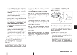
MULTI-SENSING CAMERA UNIT
MAINTENANCE
The multi-sensing camera unitj1 for the LDW sys-
tem is located in front of the interior rear vier mirror.
To maintain the proper operation of the LDW sys-
tem and prevent a system malfunction be sure to
observe the following:
•Always keep the windscreen clean.
•Do not attach a sticker (including transparent
material) or install an accessory near the multi-
sensing lane camera unit.
•Do not place reflective materials, such as white
paper or a mirror, on the instrument panel. The
reflection of sunlight may adversely affect the
multi-sensing camera unit’s detection capability.
NSD523
Starting and driving5-35
Page 212 of 338

•Do not strike or damage the areas around the
multi-sensing lane camera unit. Do not touch the
camera lens or remove the screw located on the
camera unit. If the camera unit is damaged due
to an accident, contact a NISSAN dealer or
qualified workshop.The cruise control system allows driving at constant
speeds without keeping your foot on the accelerator
pedal.
WARNING
•The cruise control system ONLY maintains a
constant vehicle speed, it does not replace
the driver.
•Always observe the posted speed limits and
do not set the speed above them.
•Do not use the cruise control system when
driving under the following conditions. Doing
so could cause a loss of vehicle control and
result in an accident.
– When it is not possible to keep the vehicle
at a constant speed
– When driving in heavy traffic
– When driving in traffic that varies speed
– When driving in windy areas
– When driving on winding or hilly roads
– When driving on slippery (rain, snow, ice,
etc.) roads
CAUTION
On manual transmission models, do not shift into
N (Neutral) without depressing the clutch pedal
when the cruise control is set. Should this occur,
depress the clutch pedal and turn the cruise con-
trol main switch off immediately. Failure to do so
may cause engine damage.When the cruise control system is on the speed lim-
iter cannot be operated.
The cruise control system operation switches are
located on the steering wheel (right side).
The cruise control system operating condition is
shown in the vehicle information display.
PRECAUTIONS ON CRUISE
CONTROL
•The cruise control system will be automatically
cancelled when there is a malfunction. Have the
system checked by a NISSAN dealer or quali-
fied workshop.
•To properly set the cruise control system, per-
form the steps as described in “Setting a cruis-
ing speed” later in this section.
CRUISE CONTROL (where fitted)
5-36Starting and driving
Page 213 of 338

CRUISE CONTROL SYSTEM
OPERATIONS
j
1CANCEL switch
jARES/+ (Resume) switch
jBSET/— switch
j2Cruise control main “ON/OFF” switch
j3Speed limiter main “ON/OFF” switch(For details, see “Speed limiter (where fitted)”
later in this section) (where fitted)
j4Cruise control symbol
j5Set speed value
Turning the cruise control system on
Push the cruise control main switchj2 . The cruise
control symbolj4 appears together with the last set
speed value (or———)j5 in the top of the vehicle
information display.
Setting a cruising speed
1. Accelerate to the desired cruising speed.
2. Push the SET switch
jB downwards and release
it.
3. The cruise control symbol
j4 appears together
with the set speed value (desired cruising speed)
j5 in the top of the vehicle information display.
4. Take your foot off the accelerator pedal.
The vehicle will maintain the set speed.If the vehicle speed is less than the minimum set
speed, it will not be possible to set the cruise
control system.
Changing a cruising speed
Use any one of the following methods to change the
cruising speed.
•Slow the vehicle as normal using the footbrake
pedal.
When the vehicle reaches the desired cruising
speed, push and release the SET switch
jB
downwards.
The new set speed value will be displayed in the
top of the vehicle information display.
•Press the accelerator pedal.
When the vehicle reaches the desired cruising
speed, push and release the SET switch
jB
downwards.
The new set speed value will be displayed in the
top of the vehicle information display.
•Push and release the RES (resume)jA switch
upwards to increase or the SET switchjB down-
wards to decrease the set speed in steps of 1
km/h (1 MPH).
The new set speed value will be displayed in the
top of the vehicle information display.
•Push and hold the RES (resume)jA switch up-
wards or the SET switchjB downwards. The
vehicle speed will increase or decrease to the
new set speed.
The new set speed value will be displayed in the
top of the vehicle information display.
NAA1385Models with speed limiter (where fitted)
NAA1386Models without speed limiter
NAA1431
Starting and driving5-37
Page 214 of 338

Passing another vehicle
Depress the accelerator pedal to accelerate. After
releasing the accelerator pedal, the vehicle will re-
turn to the previously set speed.
The set speed value
j5 will flash until the vehicle
returns to the previously set speed.
Cancelling the cruise control system
To cancel a set speed limit, push the CANCEL
switchj1.
The cruise control symbolj4 and the set speed
valuej5 disappear from the top of the vehicle infor-
mation display.
The cruise control system will also be cancelled
automatically by any of the following:
•Pressing the footbrake pedal.
•Pressing the clutch pedal.
•Shifting the shift lever to the N (Neutral) position.
First depress clutch pedal
•If the vehicle slows down more than approxi-
mately 12 km/h (8 MPH) below the set speed.
Resuming a previous cruising speed
If the cruising speed has been cancelled, the last
set speed value will be stored in the cruise control
system memory. This cruising speed can be reacti-
vated by pressing the RES (Resume) switch
jA
upwards.
If the vehicle speed is less than a minimum set
speed, it will not be possible to resume to thecruising speed.
Pressing the CANCEL switch prevents resuming
to the previous cruising speed.
Turn the cruise control system off
The cruise control system will be turned off when
one of the following operations is performed:
•Push the cruise control main “ON/OFF” switchj2 . The cruise control symbolj4 and the set
speed valuej5 will turn off in the combination
meter display
•Push the speed limiter main “ON/OFF” switchj3 . The cruise control system information in the
combination meter will be replaced with the
speed limiter information. For details see “Speed
limiter (where fitted)” later in this section.
•When the vehicle is stopped and the ignition is
turned to the off position.
Turning off the cruise control system will erase
the cruise control system memory.The speed limiter allows you to set the desired ve-
hicle speed limit. While the speed limiter is acti-
vated, you can perform normal braking and accel-
eration, but the vehicle will not exceed the set speed.
When the vehicle reaches the set speed limit or if
the set speed limit is lower than the actual vehicle
speed, the accelerator pedal will not work until the
vehicle speed drops below the set speed limit.
When the actual vehicle speed exceeds the set
speed, an audible warning will be heard a short time
after the set speed is exceeded and driver interven-
tion is not detected.
When the speed limiter is on the cruise control sys-
tem cannot be operated.WARNING
•The speed limiter will not automatically brake
the vehicle to the set speed limit.
•Always observe posted speed limits. Do not
set the speed above them.
•Always confirm the setting status of the speed
limiter in the vehicle information display.
•When the speed limiter is set, avoid hard ac-
celeration to reach the set limit to ensure that
the system can limit the speed of the vehicle
correctly.
SPEED LIMITER (where fitted)
5-38Starting and driving
Page 215 of 338

•When additional floor mats are used, be sure
that they are correctly secured and that they
cannot interfere with the accelerator pedal.
Mats not adapted to the vehicle may prevent
proper operation of the speed limiter.
The speed limiter operation switches are located on
the steering wheel (right hand side).
The speed limiter operating condition is shown on
the top of vehicle information display. For details,
see “Vehicle information display” in the “2. Instru-
ments and controls” section.
SPEED LIMITER OPERATIONS
j
1CANCEL switch
jARES + (Resume) switch
jBSET – (Set) switch
j2Cruise control main “ON/OFF” switch. (For
details, see “Cruise control (where fitted)”
earlier in this section)
j3Speed limiter main “ON/OFF” switch
j4Speed limiter symbol
j5Set speed value
Turning the speed limiter on
The speed limiter can be switched on after engine
start or when driving.
Push the speed limiter main “ON/OFF” switch
j3.
The speed limiter symbol
j4 and the set speed valuej5 will illuminate in the vehicle information display.
Setting speed limit
Push the SET switchjB (downwards).
Depending on the model:
•The speed limit will be set at the current speed.
When driving less than 30 km/h (20 MPH), the
speed limiter will be set to the minimum possible
set speed of 30 km/h (20 MPH).
•Set the speed limiter while driving over 30 km/h
(20 MPH).When the speed limit is set, the speed limiter sym-
bol
j4 and the set speed valuej5 will illuminate in
the vehicle information display. The limiter symbol
will turn green.
Changing a speed limit
Use either of the following operations to change an
active speed limit:
•Push and release the RES (Resume) switchjA
upwards or SET switchjB downwards. Each
time you do this, the set speed will increase or
decrease by 1 km/h (1 MPH).
•Push and hold the RES (Resume) switchjA
upwards or SET switchjB downwards. The set
speed will increase or decrease to the next mul-
tiple of 5 km/h (5 MPH) and then in steps of 5
km/h (5 MPH).
The new set speed limit value
j5 will be displayed
in the vehicle information display.
When the actual vehicle speed exceeds the set
speed, an audible warning will be heard a short time
after the set speed is exceeded and driver interven-
tion is not detected.
Cancelling a speed limit
To cancel a set speed limit, push the CANCEL
switchj1 . The speed limiter symbolj4 and the set
speed valuej5 in the vehicle information display will
be turned off.
It is also possible to override the speed limiter by
fully depressing the accelerator pedal beyond the
resistance point.
NAA1385
NAA1430
Starting and driving5-39
Page 216 of 338

WARNING
•The vehicle may accelerate when the speed
limiter cancels.
•When additional floor mats are used, be sure
that they are correctly secured and that they
cannot interfere with the accelerator pedal.
Mats not adapted to the vehicle may prevent
proper operation of the speed limiter.
Fully depress the accelerator pedal beyond the re-
sistance point. The speed limiter will be suspended
to allow driving above the set speed. The set speed
value
j5 will flash and an audible warning will sound.
The speed limiter will automatically resume when
the vehicle speed drops below the set speed limit.
Resuming a previous set speed
If a set speed limit has been cancelled, the set speed
will be stored in the speed limiter memory.
This speed limit can be reactivated by pressing the
RES (Resume) switch
jA upwards .
If the current vehicle speed is higher than the previ-
ous set speed, the accelerator pedal will not work
and the set speed value
j5 will flash until the vehicle
speed drops below the set speed limit.
When the actual vehicle speed exceeds the set
speed, an audible warning will be heard a short time
after the set speed is exceeded and driver interven-
tion is not detected.
Turning the speed limiter off
The speed limiter system will be turned off when
one of the following operations is performed:
•Push the speed limiter main “ON/OFF” switchj3 . The speed limiter symbolj4 and the set
speed valuej5 in the vehicle information display
will be turned off.
•Push the cruise control main “ON/OFF” switchj2 . The speed limiter information in the vehicle
information will be replaced with the cruise con-
trol information. For details see “Cruise control
(where fitted)” earlier in this section.
•When the vehicle is stopped and the ignition is
turned to the off position.
Turning off the speed limiter will erase the set
speed limit memory.
Speed limiter malfunction
If the speed limiter malfunctions, the speed limiter
symbolj4 in the vehicle information display will
flash.
Turn the speed limiter off by pushing the speed lim-
iter main “ON/OFF” switch
j3 and have the system
checked by a NISSAN dealer or qualified workshop.The forward emergency braking system can assist
the driver when there is a risk of a forward collision
with the vehicle ahead in the travelling lane.
The forward emergency braking system uses a ra-
dar sensor
jA located at the front of the vehicle to
measure the distance to the vehicle ahead in the
travelling lane.
WARNING
•The forward emergency braking system is a
supplemental aid to the driver. It is not a re-
placement for the driver’s attention to traffic
conditions or responsibility to drive safely. It
cannot prevent accidents due to carelessness
or dangerous driving techniques.
•The forward emergency braking system does
not function in all driving, traffic, weather and
road conditions.
NSD508
FORWARD EMERGENCY
BRAKING SYSTEM (where fitted)
5-40Starting and driving