Page 97 of 338

To turn the front fog lights on, turn the headlight
switch to theoror AUTO (where fitted)
position and turn the fog light switch to theposi-
tion. The front fog lights and indicator light will come
on. The fog light switch will return to the “OFF”
position (—). For additional information, see “Warn-
ing/indicator lights and audible reminders” earlier in
this section.
To turn the front fog lights off, turn the fog light
switch to the
position again. The front fog lights
and indicator light will turn off. The fog light switch
will return to the “OFF” position.
NOTE
If the headlight switch is turned to the “OFF” po-
sition(—),thefrontfoglightwillswitchoffauto-
matically.
REAR FOG LIGHT (where fitted)
The rear fog light should only be used when visibility
is seriously reduced – generally, to less than 100 m
(328 ft).
To turn the rear fog light on, turn the headlight switch
to the
oror AUTO (where fitted) position
and turn the fog light switch to theposition. The
rear fog light and indicator light will come on. The
fog light switch will return to the “OFF” position (—
). For additional information, see “Warning/indicator
lights and audible reminders” earlier in this section.If the front fog lights (where fitted) are already turned
on with the headlight switch in the
position,
you can turn on the rear fog light without first turn-
ing the headlight switch to the
or AUTO (where
fitted) position.
To turn the rear fog light off, turn the fog light switch
to the
position again.
NOTE
If the headlight switch is turned to the “OFF” po-
sition(—),therearfoglightwillswitchoffauto-
matically.
HEADLIGHT AIMING CONTROL
SWITCH (where fitted)
Depending on the number of occupants in the ve-
hicle and the load it is carrying, the headlight axis
may be higher than desired. If the vehicle is travel-
ling on a hilly road, the headlights may directly hit the
rear-view mirror of the vehicle ahead or the wind-
screen of an oncoming vehicle. The light axis can be
NIC2200LHD models
NIC2201RHD models
HEADLIGHT AIMING CONTROL
Instruments and controls2-39
Page 98 of 338

lowered using the switch located on the driver’s
side of the instrument panel, next to the steering
wheel.
The higher the number designated on the switch,
the lower the axis.
When travelling with no heavy load on a flat road,
select position 0.
AUTOMATIC AIMING CONTROL (LED
headlights)
Vehicles with LED headlights are equipped with an
automatic levelling system. The headlight axis is con-
trolled automatically.
NISSAN recommends consulting local regulations
on the use of lights.To clean the headlights, pull the windscreen washer
switch towards you while the headlight switch is in
the
position and the ignition switch is in the ON
position.
NOTE
The headlight cleaner will automatically operate
every fifth operation of the wiper and washer
switch.
HEADLIGHT CLEANER SWITCH
(where fitted)
The headlight cleaner operates when the headlight
and turn signal switch is in theposition and the
ignition switch is in the ON position.
To operate the headlight cleaner push the headlight
cleaner switch located on the driver’s side, lower
left side of the instrument panel.
CAUTION
•Do not operate the cleaner continuously for
more than 15 seconds.
•Do not operate the cleaner if the washer fluid
reservoir is empty or frozen.
See “Window washer fluid/headlight cleaner fluid
(where fitted)” in the “8. Maintenance and
do-it-yourself” section for details on refilling the res-
ervoir tank.
SIC2255ZHeadlight cleaner switch (where fitted)
HEADLIGHT CLEANER
(where fitted)
2-40Instruments and controls
Page 99 of 338

To sound the horn, push the centre pad areaj1of
the steering wheel.The front seats are warmed by built-in heaters.
The switches are located on the centre console and
can be operated independently from each other (
jA
for the left-hand side seat,jB for the right-hand side
seat).
1. Turn the ignition switch to the ON position.
NOTE
The seat heater can only be activated when
the ignition switch is in the ON position.
2. Start the engine.
3. Select the heat range:
•Press the forward part of the switch (HI)j1
to activate the “HIGH” heat setting.
•Press the rear part of the switch (LO)j2to
activate the “LOW” heat setting.
•For no heat, the switch has a central “OFF”
position between “HIGH” and “LOW”.4. The seat heater switches illuminate when either
heat setting is selected and will remain on as
long as the switch is on.
5. When the vehicle’s interior has warmed-up, or
before you leave the vehicle, be sure to turn the
seat heater system off.
CAUTION
•Do not use the seat heater system for a long
period of time when the engine is not running,
otherwise the battery could run down.
•Do not put anything on the seat that insulates
the heat, such as a blanket, cushion, seat
cover, etc. Otherwise, the seat may overheat.
•Do not place anything hard or heavy on the
seat or pierce it with a pin or similar object.
This may damage the heater.
•Any liquid spilled on a heated seat should be
removed immediately with a dry cloth.
•When cleaning the seat, never use benzine,
thinner or any similar materials.
•If any abnormalities are found or the heating
does not operate, turn off the switch and have
the system checked by a NISSAN dealer or
qualified workshop.
NIC2198NIC2199
HORN SEAT HEATING (where fitted)
Instruments and controls2-41
Page 100 of 338

WARNING
Take care as the power outlet and plug may be
hot during or immediately after use.
CAUTION
•This power outlet is not designed for use with
a cigarette lighter unit.
•Do not use with accessories that exceed a 12
volt, 120 W (10 A) power draw. Do not use
double adaptors or more than one electrical
accessory.
•Use this power outlet with the engine running
(do not use for extended periods of time with
the engine stopped or idling).
•Avoid using when the air conditioner, head-
lights or rear window defogger are on.
•When not in use, be sure that the cap is
closed. Do not allow water to come into con-
tact with the outlet.
•Before inserting or disconnecting a plug, be
sure to turn off the power switch of the elec-
trical accessory being used or remove the key
from the ignition to turn the Acc power of the
vehicle off.
•Fully push the plug in sufficiently. If sufficient
contact is not made, the plug may overheat or
the internal temperature fuse may blow.
STORAGE TRAYS
WARNING
To help prevent injury in an accident or sudden
stop, do not place sharp objects in the trays.
GLOVE BOX
WARNING
Keep the glove box lid closed while driving to
help prevent injury in an accident or a sudden
stop.
To open the glove box, lift the latch and lower the lid.
Towards the rear of the glove box an elastic strap
can be used to hold the Owner’s Manual pack.
NIC2177Centre console
NIC2135Front armrest
NIC2136
POWER OUTLET STORAGE
2-42Instruments and controls
Page 101 of 338

Sunglasses holder (where fitted)
WARNING
The sunglasses holder should not be used while
driving so that full attention may be given to ve-
hicle operation.
The glove box contains a sunglasses storage area,
which is accessible when the glove box is open.
CONSOLE BOX
WARNING
The centre console box should not be used while
driving so that full attention may be given to ve-
hicle operation.
To open the console box lid, pull the lever
j1orj2
and pull up the lid.
When the lever
j1 on the right side is pulled, the
upper case is available for storing some small items.
When the lever
j2 on the left side is pulled, the bot-
tom case is available for storing some larger ones.
To close, push the lid down until the lock latches.
The console box lid contains designated storage
areas, for example, for CDs, coins, and business
cards.
Cable slots
The console box contains openings in the sidesj1
and frontj2 to allow cables to be routed through
the console box lid. For more information, see
“Power outlet” earlier in this section and “AUX
socket” later in this section
SIC3809Z
NAA1497
Instruments and controls2-43
Page 102 of 338

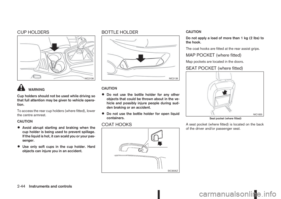
CUP HOLDERS
WARNING
Cup holders should not be used while driving so
that full attention may be given to vehicle opera-
tion.
To access the rear cup holders (where fitted), lower
the centre armrest.
CAUTION
•Avoid abrupt starting and braking when the
cup holder is being used to prevent spillage.
If the liquid is hot, it can scald you or your pas-
senger.
•Use only soft cups in the cup holder. Hard
objects can injure you in an accident.
BOTTLE HOLDER
CAUTION
•Do not use the bottle holder for any other
objects that could be thrown about in the ve-
hicle and possibly injure people during sud-
den braking or an accident.
•Do not use the bottle holder for open liquid
containers.
COAT HOOKS
CAUTION
Do not apply a load of more than 1 kg (2 lbs) to
the hook.
The coat hooks are fitted at the rear assist grips.
MAP POCKET (where fitted)
Map pockets are located in the doors.
SEAT POCKET (where fitted)
A seat pocket (where fitted) is located on the back
of the driver and/or passenger seat.
NIC2138NIC2139
SIC3505Z
NIC1835Seat pocket (where fitted)
2-44Instruments and controls
Page 103 of 338

ROOF RAIL (where fitted)
Luggage can be carried on the roof by securing
crossbars to the roof rail. Follow all crossbar manu-
facturers instructions for installing and use of the
crossbars. The roof rail is designed to carry loads
(luggage plus crossbars) below 75 kg (165 lb).
Overloading may cause damage to the vehicle.
PARCEL SHELF
WARNING
•Never put anything on the parcel shelf, no
matter how small. Any object on it could cause
an injury in case of an accident or if the brakes
are applied suddenly.
•Do not leave the parcel shelf in position when
it is disengaged from the grooves.
•Properly secure all cargo to help prevent it
from sliding or shifting. Do not place cargo
higher than the seatbacks. In a sudden stop
or collision, unsecured cargo could cause per-
sonal injury
•The child restraint top tether strap may be
damaged by contact with the parcel shelf or
items in the luggage compartment area. Re-
move the parcel shelf from the vehicle or store
it in its storage space. Also, secure any lose
items in the luggage compartment. Your child
could be seriously injured or killed in a colli-
sion if the top tether strap is damaged.
Removal
1. Open the back door (see “Back door lock” in the
“2. Pre-driving checks and adjustments” sec-
tion).
2. Detach both of the ropes (left and right)
j1 from
the inside of the back door.
3. Detach the parcel shelf by simply pulling it rear-
wards through the back door opening.
NIC1452
NIC2140
Instruments and controls2-45
Page 104 of 338
CAUTION
Make sure the parcel shelf is carefully stored
when not in use in order to prevent any damage.
NOTE
The parcel shelf can be securely stored under
the luggage compartment floor boards (see
“Installation” later in this section).
Installation
1. Open the back door.
2. Insert the parcel shelf by pushing it forwards as
far as possible through the back door opening.
3. Attach the corresponding ropes to each side
j1
of the back door.
4. Close the back door (see “Back door lock” in the
“2. Pre-driving checks and adjustments” sec-
tion).
NIC2209
NPA1312
2-46Instruments and controls