Page 12 of 380
1. Engine hood (P. 3-12)
2. Wiper and washer switch (P. 2-25)
3. Windshield (P. 8-22)
4. Power windows (if so equipped)(P. 2-46)
5. Door locks (P. 3-3) Key fob (if so equipped) (P. 3-8)
Keys (P. 3-2)
6. Mirrors (P. 3-17)
7. Tire pressure (P. 8-33)
8. Flat tire (P. 6-2)
9. Tire chains (P. 8-33)
10. Headlight and turn signal switch
(P. 2-27)
Replacing bulbs (P. 8-29)
Refer to the page number indicated in
parentheses for operating details.
LII2320
EXTERIOR FRONT
Illustrated table of contents0-3
Page 13 of 380
1. Rear window and outside mirror (if soequipped) defroster switch (P. 2-26)
2. Trailer hitch/towing (P. 9-17)
3 Replacing bulbs (P. 8-29)
4. Fuel-filler cap (P. 3-13) Fuel recommendation (P. 9-2)
5. Fuel-filler door (P. 3-13)
6. Vehicle loading (P. 9-13)
Refer to the page number indicated in pa-
rentheses for operating details.
LII2004
EXTERIOR REAR
0-4Illustrated table of contents
Page 14 of 380
1. Map lights (P. 2-48)
2. Sun visors (P. 3-16)
3. Inside mirror (P. 3-17)
4. Steering wheel (P. 3-15)
5. Glove box (P. 2-38)
6. Console box (if so equipped) (P. 2-38)
7. Front seats (P. 1-2)
8. Cup holders (mounted to lower seatframe) (2nd row shown; 3rd and 4th
rows similar) (P. 2-38)
9. Rear seat configurations (P. 1-2)
Refer to the page number indicated in pa-
rentheses for operating details.
LII2024
PASSENGER COMPARTMENT
Illustrated table of contents0-5
Page 16 of 380
17. Rear sonar system OFF switch(if so equipped) (P. 2-32)
Tow mode ON switch (if so equipped)
(P. 2-33)
Front and rear sonar system OFF
switch (if so equipped) (P. 2-33)
Heated seat switch (if so equipped)
(P. 2-30)
Power inverter switch (if so equipped)
(P. 2-31)
18. 12v power outlet (P. 2-34)
19. Ignition switch (P. 5-8)
20. Tilt steering wheel control (P. 3-15)
21. Hood release switch (P. 3-12)
22. Fuse box (P. 8-24)
23. Outside power mirror switch (P. 3-18) Vehicle Dynamic Control (VDC) OFF
switch (P. 2-31)
*: Refer to the separate Navigation System Own-
er’s Manual (if so equipped) .
Refer to the page number indicated in pa-
rentheses for operating details.
Illustrated table of contents0-7
Page 85 of 380

2 Instruments and controls
Instrument panel...................................2-2
Meters and gauges ................................2-3
Speedometer and odometer .....................2-4
Tachometer ....................................2-5
Engine coolant temperature gauge ...............2-5
Fuel gauge ....................................2-6
Engine oil pressure gauge .......................2-6
Voltmeter ......................................2-7
Automatic transmission fluid temperature
gauge .........................................2-7
Compass (if so equipped) ..........................2-8
Compass display (if so equipped) ................2-8
Warning lights, indicator lights and audible
reminders ........................................ 2-11
Checking lights ............................... 2-11
Warning lights ................................ 2-12
Indicator lights ................................ 2-16
Audible reminders ............................. 2-18
Vehicle Information Display ........................2-18
How to use the Vehicle Information Display .......2-18
Security systems (if so equipped) ..................2-23
Vehicle security system (if so equipped) ..........2-23
NISSAN vehicle immobilizer system
(if so equipped) ............................... 2-24Wiper and washer switch
......................... 2-25
Switch operation .............................. 2-25
Rear window and outside mirror (if so equipped)
defroster switch .................................. 2-26
Headlight and turn signal switch ....................2-27
Headlight control switch ........................ 2-27
Daytime running light system ....................2-28
Instrument brightness control ...................2-29
Turn signal switch ............................. 2-29
Fog light switch (if so equipped) ................2-29
Horn ............................................ 2-30
Heated seats (if so equipped) ......................2-30
Vehicle Dynamic Control (VDC) off switch ...........2-31
Power inverter switch (if so equipped) ..............2-31
Rear sonar system off switch (if so equipped) ........2-32
Front and rear sonar system off switch
(if so equipped) .................................. 2-33
T
ow mode switch (if so equipped) ..................2-33
Power outlets .................................... 2-34
12v outlet(s) .................................. 2-34
120v outlets (if so equipped) ...................2-37
Storage ......................................... 2-38
Map pockets .................................. 2-38
Page 88 of 380
17. Rear sonar system OFF switch(if so equipped) (P. 2-32)
Tow mode ON switch (if so equipped)
(P. 2-33)
Front and rear sonar system OFF
switch (if so equipped) (P. 2-33)
Heated seat switch (if so equipped)
(P. 2-30)
Power inverter switch (if so equipped)
(P. 2-31)
18. 12v power outlet (P. 2-34)
19. Ignition switch (P. 5-8)
20. Tilt steering wheel control (P. 3-15)
21. Hood release switch (P. 3-12)
22. Fuse box (P. 8-24)
23. Outside power mirror switch (P. 3-18) Vehicle Dynamic Control (VDC) OFF
switch (P. 2-31)
*: Refer to the separate Navigation System Own-
er’s Manual (if so equipped) .
Refer to the page number indicated in pa-
rentheses for operating details.
1. Warning lights and indicator lights
2. Tachometer
3. Speedometer
4. Fuel gauge
5. Twin trip button and instrument bright-
ness control knob 6. Vehicle information display
7. INFO button and digital gauge change
knob
8. Engine coolant temperature gauge
LIC2037
METERS AND GAUGES
Instruments and controls2-3
Page 93 of 380

CAUTION
●This gauge is not designed to indicate
low automatic transmission fluid level.
Use the dipstick to check the fluid level.
For additional information, refer to “5-
speed automatic transmission fluid” in
the “Maintenance and do-it-yourself”
section of this manual.
● If the gauge indicates automatic trans-
mission fluid temperature over the nor-
mal range, stop the vehicle as soon as
safely possible. Have the vehicle
checked by a NISSAN dealer. Continued
operation of the vehicle may seriously
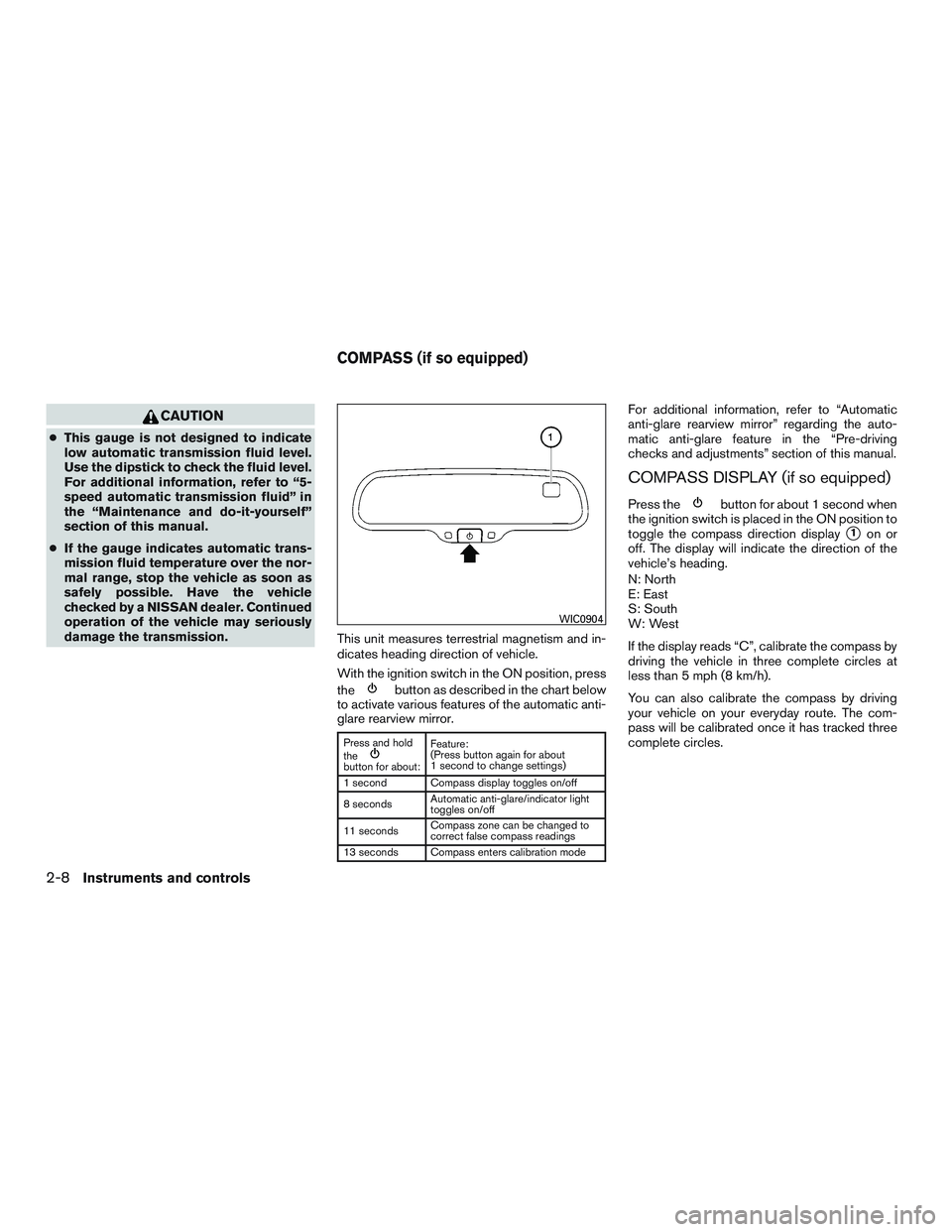
damage the transmission. This unit measures terrestrial magnetism and in-
dicates heading direction of vehicle.
With the ignition switch in the ON position, press
the
button as described in the chart below
to activate various features of the automatic anti-
glare rearview mirror.
Press and hold
the
button for about: Feature:
(Press button again for about
1 second to change settings)
1 second Compass display toggles on/off
8 seconds Automatic anti-glare/indicator light
toggles on/off
11 seconds Compass zone can be changed to
correct false compass readings
13 seconds Compass enters calibration mode
For additional information, refer to “Automatic
anti-glare rearview mirror” regarding the auto-
matic anti-glare feature in the “Pre-driving
checks and adjustments” section of this manual.
COMPASS DISPLAY (if so equipped)
Press thebutton for about 1 second when
the ignition switch is placed in the ON position to
toggle the compass direction display
�1on or
off. The display will indicate the direction of the
vehicle’s heading.
N: North
E: East
S: South
W: West
If the display reads “C”, calibrate the compass by
driving the vehicle in three complete circles at
less than 5 mph (8 km/h).
You can also calibrate the compass by driving
your vehicle on your everyday route. The com-
pass will be calibrated once it has tracked three
complete circles.
WIC0904
COMPASS (if so equipped)
2-8Instruments and controls
Page 95 of 380
1. With the display turned on, press and holdthe
button for about 13 seconds. The
“C” icon in the compass display will illumi-
nate.
2. Calibrate the compass by driving the vehicle in three complete circles at a maximum
speed of 5 mph (8 km/h).
3. After completing the circles, the display should return to normal.
CAUTION
●Do not install a ski rack, antenna, etc.,
which are attached to the vehicle by
means of a magnet. They affect the op-
eration of the compass.
● When cleaning the mirror, use a paper
towel or similar material dampened
with glass cleaner. Do not spray glass
cleaner directly on the mirror as it may
cause the liquid cleaner to enter the
mirror housing.
2-10Instruments and controls