2016 NISSAN NOTE impact sensor
[x] Cancel search: impact sensorPage 593 of 3641
![NISSAN NOTE 2016 Service Repair Manual ABS ACTUATOR AND ELECTRIC UNIT (CONTROL UNIT)BRC-145
< REMOVAL AND INSTALLATION > [VDC/TCS/ABS]
C
D
E
G H
I
J
K L
M A
B
BRC
N
O P
3. Remove ground harness bolt (A) and ground harness from radi- ator c](/manual-img/5/57363/w960_57363-592.png "NISSAN NOTE 2016 Service Repair Manual ABS ACTUATOR AND ELECTRIC UNIT (CONTROL UNIT)BRC-145
< REMOVAL AND INSTALLATION > [VDC/TCS/ABS]
C
D
E
G H
I
J
K L
M A
B
BRC
N
O P
3. Remove ground harness bolt (A) and ground harness from radi- ator c")
ABS ACTUATOR AND ELECTRIC UNIT (CONTROL UNIT)BRC-145
< REMOVAL AND INSTALLATION > [VDC/TCS/ABS]
C
D
E
G H
I
J
K L
M A
B
BRC
N
O P
3. Remove ground harness bolt (A) and ground harness from radi- ator core support.
4. Disconnect high-pressure pipe from expansion valve. Refer to HA-28, "
Exploded View".
CAUTION:
Cap or wrap the joint of the A/C piping and expan sion valve with suitable material such as vinyl
tape to avoid the entry of air.
5. Remove low-pressure flexible hose. Refer to HA-28, "
LOW-PRESSURE FLEXIBLE HOSE : Removal and
Installation".
6. Loosen flare nut from brake tubes using a flare nut wrench, then remove brake tubes from ABS actuator
and electric unit (control unit). Refer to BR-22, "
FRONT : Exploded View".
7. Disconnect the harness connector from the ABS actuator and electric unit (control unit).
8. Remove ABS actuator and electric unit (control unit) bracket bolts.
9. Remove the ABS actuator and electric uni t (control unit) and bracket as an assembly.
10. Remove bracket and bushing from ABS ac tuator and electric unit (if necessary).
INSTALLATION
Installation is in the reverse order of removal.
• Bleed the brake system. Refer to BR-13, "
Bleeding Brake System".
• Adjust the neutral position of steering angle sensor. Refer to BRC-55, "
ADJUSTMENT OF STEERING
ANGLE SENSOR NEUTRAL POSITION : Special Repair Requirement".
CAUTION:
• Replace the ABS actuator electric unit (control unit) if it has been dropped or sustained an impact.
• Do not install actuator by holding harness.
• After installing harness connector in the ABS acu tator and electric until (control unit), make sure
harness connector is securely locked.
ALKIA3174ZZ
Revision: August 2015 2016 Versa Note
cardiagn.com
Page 1033 of 3641
![NISSAN NOTE 2016 Service Repair Manual EM-32
< REMOVAL AND INSTALLATION >[HR16DE]
EXHAUST MANIFOLD
6. Use Tool (A) to remove the air-fuel ratio sensor 1 with exhaust
manifold installed on vehicle (if necessary).
CAUTION:
• Handle air-fue](/manual-img/5/57363/w960_57363-1032.png "NISSAN NOTE 2016 Service Repair Manual EM-32
< REMOVAL AND INSTALLATION >[HR16DE]
EXHAUST MANIFOLD
6. Use Tool (A) to remove the air-fuel ratio sensor 1 with exhaust
manifold installed on vehicle (if necessary).
CAUTION:
• Handle air-fue")
EM-32
< REMOVAL AND INSTALLATION >[HR16DE]
EXHAUST MANIFOLD
6. Use Tool (A) to remove the air-fuel ratio sensor 1 with exhaust
manifold installed on vehicle (if necessary).
CAUTION:
• Handle air-fuel ratio sensor 1 carefully and avoid impacts.
• Before installing a new air-fu el ratio sensor 1, clean the
exhaust tube threads using suitable tool and approved
anti-seize lubricant.
• If air-fuel ratio sensor is dropped onto a hard surface, such as a concrete floor, from a height of 0.5 m or more,
discard the sensor and use a new one.
7. Remove exhaust manifold side bolt of exhaust manifold stay.
8. Remove exhaust manifold. • Loosen nuts in reverse order as shown.
9. Remove exhaust manifold gasket.
10. Remove stud bolt using suitable tool from cylinder head (if necessary).
INSPECTION AFTER REMOVAL
Mounting Surface Distortion
• Using suitable tools (A) and (B), check the surface distortion of the exhaust manifold mating surface as shown.
• Replace exhaust manifold if it exceeds the limit.
INSTALLATION
Installation is in the reverse order of removal.
Exhaust manifold
1. Install new exhaust manifold gasket. CAUTION:Tool number (A) : KV10117100 ( — )
Oxygen sensor thread cleaner : — (J-43897-12)
: — (J-43897-18)
JPBIA4126ZZ
JPBIA4127ZZ
Limit : Refer to EM-117, "Exhaust Manifold".
PBIC3530J
Revision: August 2015 2016 Versa Note
cardiagn.com
Page 1034 of 3641
![NISSAN NOTE 2016 Service Repair Manual EXHAUST MANIFOLDEM-33
< REMOVAL AND INSTALLATION > [HR16DE]
C
D
E
F
G H
I
J
K L
M A
EM
NP
O
Do not reuse exhaust manifold gasket.
2. Tighten nuts in numerical order as shown.
3. Tighten nuts in numeri](/manual-img/5/57363/w960_57363-1033.png "NISSAN NOTE 2016 Service Repair Manual EXHAUST MANIFOLDEM-33
< REMOVAL AND INSTALLATION > [HR16DE]
C
D
E
F
G H
I
J
K L
M A
EM
NP
O
Do not reuse exhaust manifold gasket.
2. Tighten nuts in numerical order as shown.
3. Tighten nuts in numeri")
EXHAUST MANIFOLDEM-33
< REMOVAL AND INSTALLATION > [HR16DE]
C
D
E
F
G H
I
J
K L
M A
EM
NP
O
Do not reuse exhaust manifold gasket.
2. Tighten nuts in numerical order as shown.
3. Tighten nuts in numerical order to the specified torque again.
Air-fuel ratio sensor 1
• Use Tool (A) to install the air-fuel ratio sensor 1 (if removed). CAUTION:
• Handle it carefully and avoid impacts.
• Before installing a new air-fu el ratio sensor 1, clean the
exhaust tube threads using suit able tool and approved anti-
seize lubricant.
• Do not over-tighten the air-fuel ratio sensor 1. Doing so may damage the air-fuel ratio senso r 1, resulting in the MIL com-
ing on.
INSPECTION AFTER INSTALLATION
Inspection
• Start engine and raise engine speed to check for exhaust leaks.
JPBIA4127ZZ
JPBIA4127ZZ
Tool number (A) : KV10117100 ( — )
Oxygen sensor thread cleaner : — (J-43897-12)
: — (J-43897-18)
JPBIA4126ZZ
Revision: August 2015 2016 Versa Note
cardiagn.com
Page 1095 of 3641
![NISSAN NOTE 2016 Service Repair Manual EM-94
< UNIT DISASSEMBLY AND ASSEMBLY >[HR16DE]
CYLINDER BLOCK
Disassembly and Assembly
INFOID:0000000012431737
DISASSEMBLY
NOTE:
The following procedures explain how to disassem ble the engine with t](/manual-img/5/57363/w960_57363-1094.png "NISSAN NOTE 2016 Service Repair Manual EM-94
< UNIT DISASSEMBLY AND ASSEMBLY >[HR16DE]
CYLINDER BLOCK
Disassembly and Assembly
INFOID:0000000012431737
DISASSEMBLY
NOTE:
The following procedures explain how to disassem ble the engine with t")
EM-94
< UNIT DISASSEMBLY AND ASSEMBLY >[HR16DE]
CYLINDER BLOCK
Disassembly and Assembly
INFOID:0000000012431737
DISASSEMBLY
NOTE:
The following procedures explain how to disassem ble the engine with the engine stand fastened to the bell
housing. Some steps may be different if using a different type of engine stand.
1. Remove cylinder head. Refer to EM-76, "
Exploded View".
2. Remove knock sensor. CAUTION:
Carefully handle knock sensor avoiding shocks.
3. Remove the crankshaft position sensor cover (3), and then crankshaft position sensor (POS) (2).
CAUTION:
• Avoid impacts such as a dropping.
• Do not disassemble.
• Keep sensor away from metal particles.
• Do not place the sensor in a location where it is exposed
to magnetism.
• Do not reuse O-ring.
4. Remove oil pan (upper and lower). Refer to EM-34
.
5. Remove piston and connecting rod assembly: • Before removing piston and connecting rod assembly, check the connecting rod side clearance. Refer toEM-102, "
Inspection".
a. Position crankshaft pin corresponding to connecting rod to be removed onto the bottom dead center.
b. Remove connecting rod cap.
c. Using a hammer handle or similar tool, push piston and connect- ing rod assembly out through the cylinder head side.
CAUTION:
• Do not damage mating surface with connecting rod cap.
• Do not damage the cylinder wall or crankshaft pin.
6. Remove connecting rod bearings. CAUTION:
Identify original positions for installation, an d store the bearings without mixing them up.
10. Oil temperature sensor 11. Oil pressure sensor12. Oil jet
13. Top ring 14. Second ring15. Oil rings
16. Piston 17. Piston pin18. Connecting rod
19. Connecting rod bearing (upper) 20. Main bearing (upper) 21. Thrust bearing
22. Crankshaft key 23. Connecting rod bolt24. Connecting rod cap
25. Connecting rod bearing (lower) 26. Main bearing (lower) 27. Crankshaft
28. Pilot converter (CVT models) 29. Signal plate30. Rear oil seal
31. Drive plate (CVT models) 32. Reinforce plate (CVT models) 33. Flywheel (M/T models)
34. Main bearing cap 35. Main bearing cap bolt A. Refer to ASSEMBLY
B. Chamfered Crankshaft side
(1) O-ring
(4) Cylinder block
: Engine front
JPBIA4202ZZ
KBIA3365J
Revision: August 2015 2016 Versa Note
cardiagn.com
Page 1102 of 3641
![NISSAN NOTE 2016 Service Repair Manual CYLINDER BLOCKEM-101
< UNIT DISASSEMBLY AND ASSEMBLY > [HR16DE]
C
D
E
F
G H
I
J
K L
M A
EM
NP
O
Install the rear oil seal after installing the oil pan (upper).
17. Install rear oil seal. Refer to EM-](/manual-img/5/57363/w960_57363-1101.png "NISSAN NOTE 2016 Service Repair Manual CYLINDER BLOCKEM-101
< UNIT DISASSEMBLY AND ASSEMBLY > [HR16DE]
C
D
E
F
G H
I
J
K L
M A
EM
NP
O
Install the rear oil seal after installing the oil pan (upper).
17. Install rear oil seal. Refer to EM-")
CYLINDER BLOCKEM-101
< UNIT DISASSEMBLY AND ASSEMBLY > [HR16DE]
C
D
E
F
G H
I
J
K L
M A
EM
NP
O
Install the rear oil seal after installing the oil pan (upper).
17. Install rear oil seal. Refer to EM-74, "
REAR OIL SEAL : Removal and Installation".
18. Install flywheel (M/T models) or drive plate (CVT models).
M/T models
• Secure crankshaft with a stopper plate and tighten bolts crosswise over several times.
CVT models
• Secure crankshaft with a stopper plate and tighten bolts crosswise over several times.
CAUTION:
Do not damage or scratch and contact surface for clutch disc of flywheel.
19. Install knock sensor (1).
• Install connectors so that they are positioned toward the rearof the engine.
CAUTION:
• Do not tighten bolt while holding the connector.
• If any impact by dropping is applied to knock sensor,
replace it with a new one.
NOTE:
• Check that there is no foreign material on the cylinder block
mating surface and the back surface of knock sensor.
• Check that knock sensor does not interfere with other parts.
20. Install crankshaft position sensor (POS) (2) and O-ring (1) and then install the crankshaft position sensor cover (3) on the cylin-
der block (4).
• Tighten bolts with sensor inserted completely.
CAUTION:
• Avoid impacts such as a dropping.
• Do not disassemble.
• Keep sensor away from metal particles.
• Do not place the sensor in a location where it is exposedto magnetism.
• Do not reuse O-ring.
21. For the oil level gauge guide (1), secure in position (B) shown to the water inlet clip (A) after inserting to the cylinder block side.
22. Assembly of the remaining components is in the reverse order of disassembly.
Tool number : KV11105210 (J-44716)
Tool number : KV11105210 (J-44716)
: Engine front
: Engine front
PBIC3754E
JPBIA4202ZZ
PBIC3755E
Revision: August 2015
2016 Versa Note
cardiagn.com
Page 1874 of 3641
FL -8
< REMOVAL AND INSTALLATION >
FUEL LEVEL SENSOR UNIT, FUEL FILTER AND FUEL PUMP ASSEMBLY
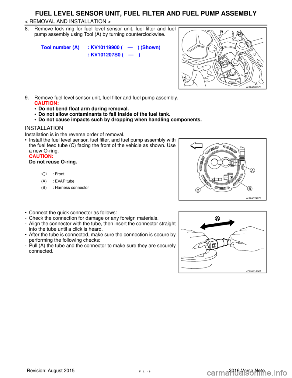
8. Remove lock ring for fuel level sensor unit, fuel filter and fuel
pump assembly using Tool (A) by turning counterclockwise.
9. Remove fuel level sensor unit, fuel filter and fuel pump assembly. CAUTION:
• Do not bend float arm during removal.
• Do not allow contaminants to fa ll inside of the fuel tank.
• Do not cause impacts such by dro pping when handling components.
INSTALLATION
Installation is in the reverse order of removal.
• Install the fuel level sensor, fuel filter, and fuel pump assembly with
the fuel feed tube (C) facing the front of the vehicle as shown. Use
a new O-ring.
CAUTION:
Do not reuse O-ring.
• Connect the quick connector as follows:
- Check the connection for damage or any foreign materials.
- Align the connector with the tube, then insert the connector straight into the tube until a click is heard.
• After the tube is connected, make sure the connection is secure by performing the following checks:
- Pull (A) the tube and the connector to make sure they are securely
connected. Tool number (A) : KV10119900 ( — ) (Shown)
: KV101207S0 ( — )
ALBIA1059ZZ
: Front
(A) : EVAP tube
(B) : Harness connector
ALBIA0747ZZ
JPBIA0140ZZ
Revision: August 2015 2016 Versa Note
cardiagn.com
Page 2660 of 3641
PG
BATTERY CURRENT SENSORPG-73
< REMOVAL AND INSTALLATION >
C
DE
F
G H
I
J
K L
B A
O P
N
BATTERY CURRENT SENSOR
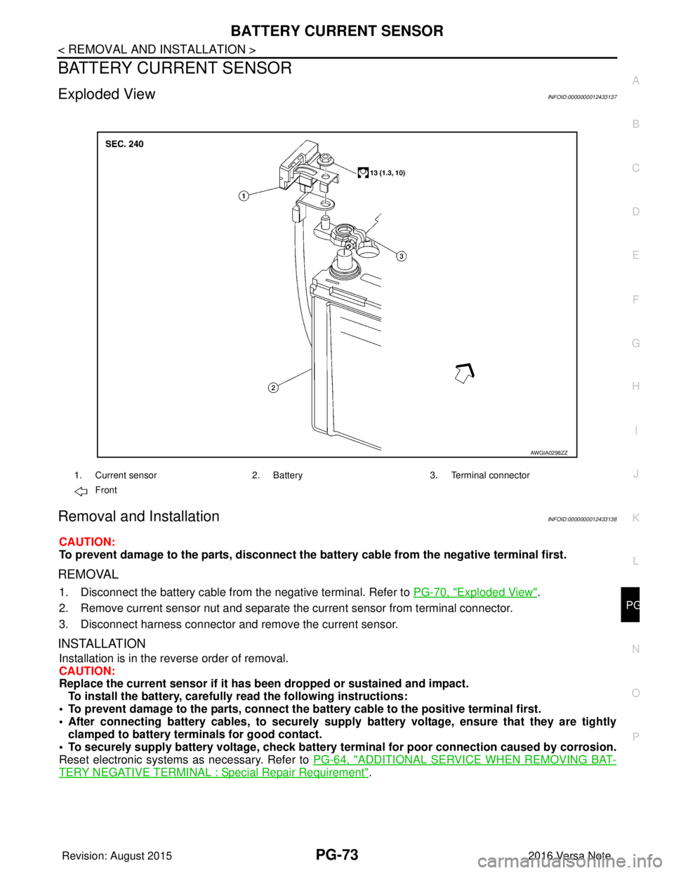
Exploded ViewINFOID:0000000012433137
Removal and InstallationINFOID:0000000012433138
CAUTION:
To prevent damage to the parts, disconnect the battery cable from the negative terminal first.
REMOVAL
1. Disconnect the battery cable from
the negative terminal. Refer to PG-70, "Exploded View".
2. Remove current sensor nut and separate the current sensor from terminal connector.
3. Disconnect harness connector and remove the current sensor.
INSTALLATION
Installation is in the reverse order of removal.
CAUTION:
Replace the current sensor if it has b een dropped or sustained and impact.
To install the battery, carefully read the following instructions:
• To prevent damage to the parts, connect the battery cable to the positive terminal first.
• After connecting battery cables, to securely supp ly battery voltage, ensure that they are tightly
clamped to battery terminals for good contact.
• To securely supply battery voltage, check battery terminal for poor connection caused by corrosion.
Reset electronic systems as necessary. Refer to PG-64, "
ADDITIONAL SERVICE WHEN REMOVING BAT-
TERY NEGATIVE TERMINAL : Special Repair Requirement".
AWGIA0298ZZ
1. Current sensor2. Battery3. Terminal connector
Front
Revision: August 2015 2016 Versa Note
cardiagn.com
Page 2725 of 3641
REAR WHEEL HUBRAX-7
< REMOVAL AND INSTALLATION >
CEF
G H
I
J
K L
M A
B
RAX
N
O P
• Do not hammer the wheel stud a nd avoid impact to the brake drum.
• Press the wheel stud straight out to avoid damage.
7. Perform inspection after removal. Refer to RAX-9, "
Inspection".
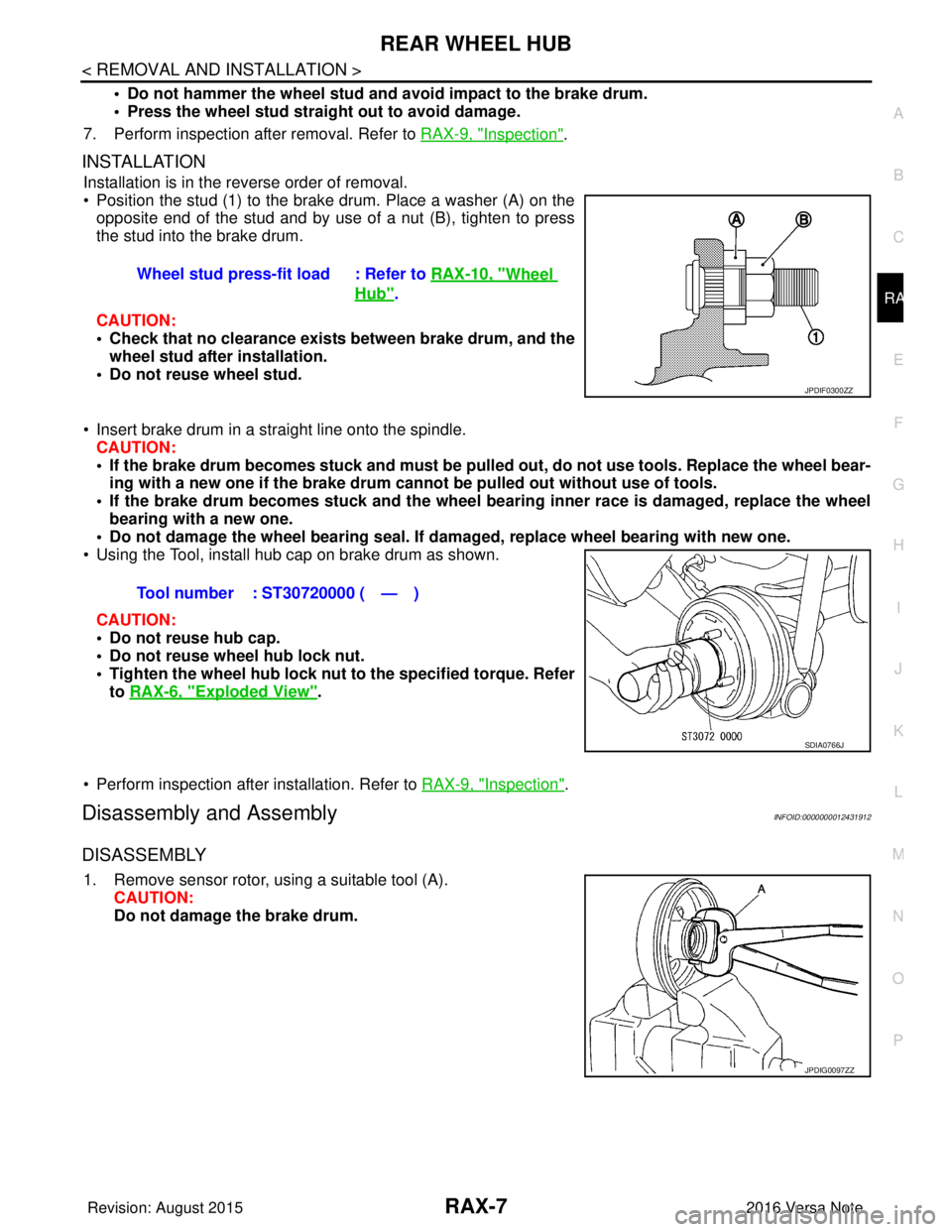
INSTALLATION
Installation is in the reverse order of removal.
• Position the stud (1) to the brake drum. Place a washer (A) on the
opposite end of the stud and by use of a nut (B), tighten to press
the stud into the brake drum.
CAUTION:
• Check that no clearance exists between brake drum, and the wheel stud after installation.
• Do not reuse wheel stud.
• Insert brake drum in a straight line onto the spindle. CAUTION:
• If the brake drum becomes stuck and must be pulled out, do not use tools. Replace the wheel bear-
ing with a new one if the brake drum canno t be pulled out without use of tools.
• If the brake drum becomes stuck and the wheel bearing inner race is damaged, replace the wheel
bearing with a new one.
• Do not damage the wheel bearing seal. If da maged, replace wheel bearing with new one.
• Using the Tool, install hub cap on brake drum as shown.
CAUTION:
• Do not reuse hub cap.
• Do not reuse wheel hub lock nut.
• Tighten the wheel hub lock nut to the specified torque. Refer
to RAX-6, "
Exploded View".
• Perform inspection after installation. Refer to RAX-9, "
Inspection".
Disassembly and AssemblyINFOID:0000000012431912
DISASSEMBLY
1. Remove sensor rotor, using a suitable tool (A). CAUTION:
Do not damage the brake drum.Wheel stud press-fit load : Refer to
RAX-10, "
Wheel
Hub".
JPDIF0300ZZ
Tool number : ST30720000 ( — )
SDIA0766J
JPDIG0097ZZ
Revision: August 2015 2016 Versa Note
cardiagn.com