2016 NISSAN NOTE boot
[x] Cancel search: bootPage 2354 of 3641
CHASSIS AND BODY MAINTENANCEMA-39
< PERIODIC MAINTENANCE >
C
DE
F
G H
I
J
K L
M B
MA
N
O A
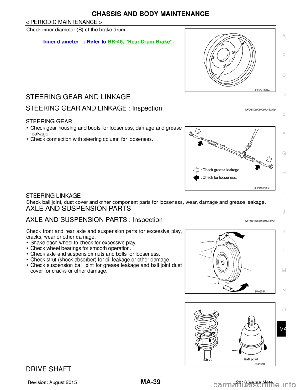
Check inner diameter (B) of the brake drum.
STEERING GEAR AND LINKAGE
STEERING GEAR AND LINKAGE : InspectionINFOID:0000000012432290
STEERING GEAR
• Check gear housing and boots for looseness, damage and grease
leakage.
• Check connection with steering column for looseness.
STEERING LINKAGE
Check ball joint, dust cover and other component parts for looseness, wear, damage and grease leakage.
AXLE AND SUSPENSION PARTS
AXLE AND SUSPENSION PARTS : InspectionINFOID:0000000012432291
Check front and rear axle and suspension parts for excessive play,
cracks, wear or other damage.
• Shake each wheel to check for excessive play.
• Check wheel bearings for smooth operation.
• Check axle and suspension nuts and bolts for looseness.
• Check strut (shock absorber) for oil leakage or other damage.
• Check suspension ball joint for grease leakage and ball joint dust
cover for cracks or other damage.
DRIVE SHAFT
Inner diameter : Refer to BR-46, "Rear Drum Brake".
JPFIA0113ZZ
JPPIA0013GB
SMA525A
SFA392B
Revision: August 2015 2016 Versa Note
cardiagn.com
Page 2355 of 3641
MA-40
< PERIODIC MAINTENANCE >
CHASSIS AND BODY MAINTENANCE
DRIVE SHAFT : Inspection
INFOID:0000000012432292
Check boot and drive shaft for cracks, wear, damage and grease
leakage.
LOCKS, HINGES AND HOOD LATCH
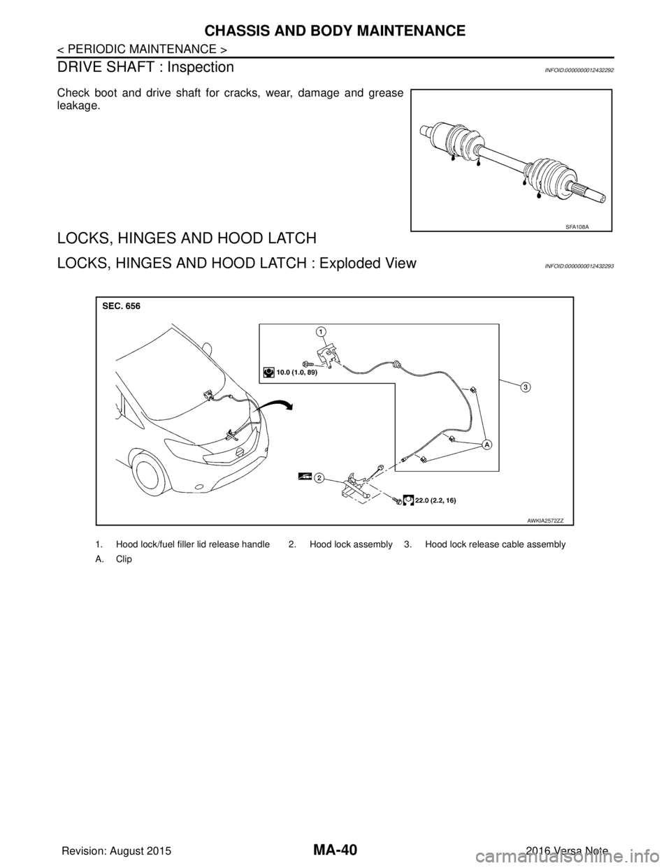
LOCKS, HINGES AND HOOD LATCH : Exploded ViewINFOID:0000000012432293
SFA108A
1. Hood lock/fuel filler lid release handle 2. Hood lock assembly 3. Hood lock release cable assembly
A. Clip
AWKIA2572ZZ
Revision: August 2015 2016 Versa Note
cardiagn.com
Page 3187 of 3641
PRECAUTIONSSTC-3
< PRECAUTION >
C
DE
F
H I
J
K L
M A
B
STC
N
O P
PRECAUTION
PRECAUTIONS
Precaution for Supplemental Restraint System (SRS) "AIR BAG" and "SEAT BELT
PRE-TENSIONER"
INFOID:0000000012431939
The Supplemental Restraint System such as “AIR BAG” and “SEAT BELT PRE-TENSIONER”, used along
with a front seat belt, helps to reduce the risk or severi ty of injury to the driver and front passenger for certain
types of collision. Information necessary to service the system safely is included in the SR and SB section of
this Service Manual.
WARNING:
• To avoid rendering the SRS inoper ative, which could increase the risk of personal injury or death in
the event of a collision which would result in air bag inflation, all maintenance must be performed by
an authorized NISSAN/INFINITI dealer.
• Improper maintenance, including in correct removal and installation of the SRS, can lead to personal
injury caused by unintentional act ivation of the system. For removal of Spiral Cable and Air Bag
Module, see the SR section.
• Do not use electrical test equipm ent on any circuit related to the SRS unless instructed to in this
Service Manual. SRS wiring harnesses can be identi fied by yellow and/or orange harnesses or har-
ness connectors.
PRECAUTIONS WHEN USING POWER TOOLS (AIR OR ELECTRIC) AND HAMMERS
WARNING:
• When working near the Airbag Diagnosis Sensor Un it or other Airbag System sensors with the Igni-
tion ON or engine running, DO NOT use air or el ectric power tools or strike near the sensor(s) with a
hammer. Heavy vibration could activate the sensor( s) and deploy the air bag(s), possibly causing
serious injury.
• When using air or electric power tools or hammers, always switch the Ignition OFF, disconnect the
battery and wait at least three mi nutes before performing any service.
Service Notice and Precautions for EPS SystemINFOID:0000000012431940
• Check the following item when performing the trouble diagnosis:
- Check for possible causes of the malfunction by inte rviewing the customer as to what conditions were
present when the symptom occurred.
- Check if the steering wheel and the EPS control unit are genuine parts.
- Check if the air pressure and size of each tire is correct.
- Check if the installation of the links and suspension components are correct.
- Check if the tires are worn evenly, indicating the wheel alignment is correct.
- Check if the installation of the steering column and t he steering gear are correct. Check for loose bolts, dam-
aged links, cracked boots and leaking grease, etc.
- Check for damage or modification to suspension or body resulting in increased weight or altered ground clearance.
- Check if the battery voltage is proper.
- Check the EPS control unit harness to be sure the harness connectors are fully seated.
• Before connecting or disconnecting the EPS control uni t harness connector, turn ignition switch “OFF” and
disconnect the battery cable from the negative terminal. Battery voltage is applied to the EPS control unit
even if ignition switch is turned “OFF”.
Revision: August 2015 2016 Versa Note
cardiagn.com
Page 3224 of 3641
PREPARATIONST-3
< PREPARATION >
C
DE
F
H I
J
K L
M A
B
ST
N
O P
PREPARATION
PREPARATION
Special Service ToolINFOID:0000000012430495
The actual shape of the tools may di ffer from those illustrated here.
Commercial Service ToolINFOID:0000000012430496
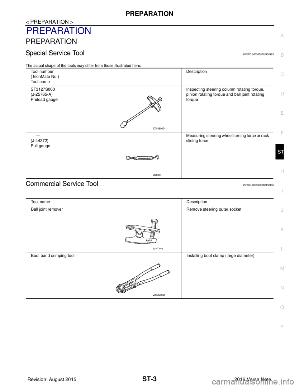
Tool number
(TechMate No.)
Tool name Description
ST3127S000
(J-25765-A)
Preload gauge Inspecting steering column rotating torque,
pinion rotating torque and ball joint rotating
torque
—
(J-44372)
Pull gauge Measuring steering wheel turning force or rack
sliding force
ZZA0806D
LST024
Tool name
Description
Ball joint remover Remove steering outer socket
Boot band crimping tool Installing boot clamp (large diameter)
S-NT146
ZZA1229D
Revision: August 2015 2016 Versa Note
cardiagn.com
Page 3237 of 3641
ST-16
< UNIT DISASSEMBLY AND ASSEMBLY >
STEERING GEAR AND LINKAGE
UNIT DISASSEMBLY AND ASSEMBLY
STEERING GEAR AND LINKAGE
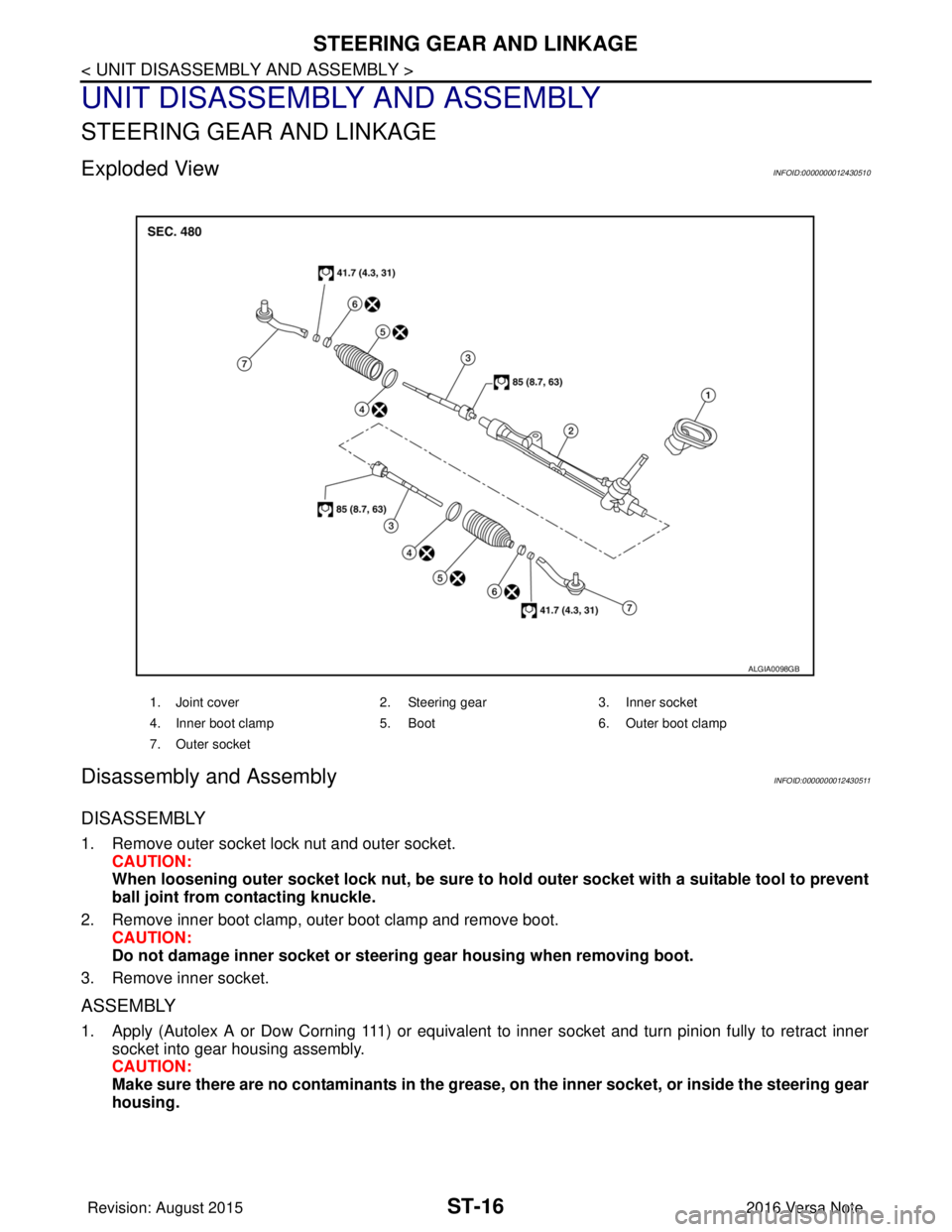
Exploded ViewINFOID:0000000012430510
Disassembly and AssemblyINFOID:0000000012430511
DISASSEMBLY
1. Remove outer socket lock nut and outer socket.CAUTION:
When loosening outer socket lock nut, be sure to hold outer socket with a suitable tool to prevent
ball joint from contacting knuckle.
2. Remove inner boot clamp, outer boot clamp and remove boot. CAUTION:
Do not damage inner socket or steerin g gear housing when removing boot.
3. Remove inner socket.
ASSEMBLY
1. Apply (Autolex A or Dow Corning 111) or equivalent to inner socket and turn pinion fully to retract inner socket into gear housing assembly.
CAUTION:
Make sure there are no contaminants in the grease, on the inner socket, or inside the steering gear
housing.
1. Joint cover 2. Steering gear3. Inner socket
4. Inner boot clamp 5. Boot6. Outer boot clamp
7. Outer socket
ALGIA0098GB
Revision: August 2015 2016 Versa Note
cardiagn.com
Page 3238 of 3641
STEERING GEAR AND LINKAGEST-17
< UNIT DISASSEMBLY AND ASSEMBLY >
C
DE
F
H I
J
K L
M A
B
ST
N
O P
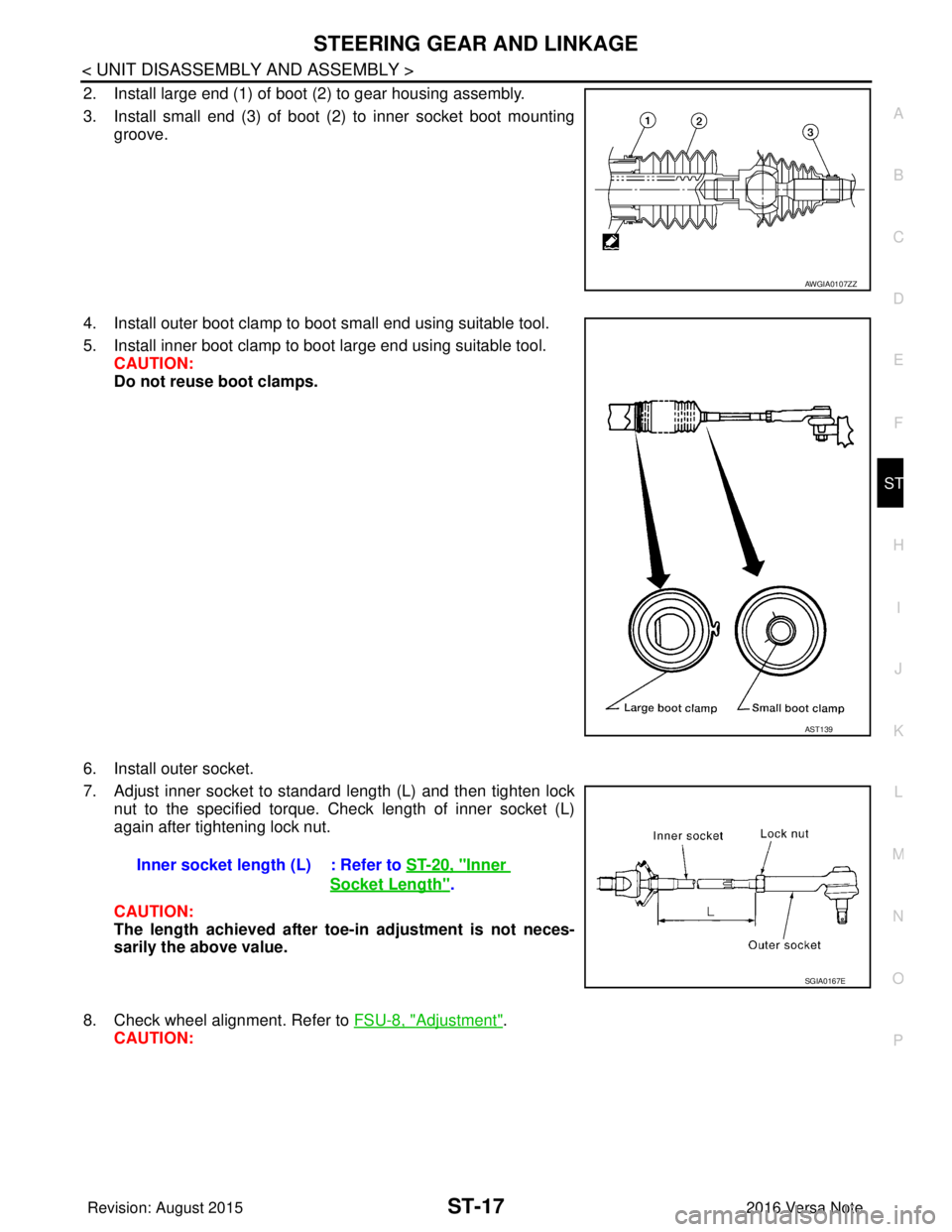
2. Install large end (1) of boot (2) to gear housing assembly.
3. Install small end (3) of boot (2) to inner socket boot mounting groove.
4. Install outer boot clamp to boot small end using suitable tool.
5. Install inner boot clamp to boot large end using suitable tool. CAUTION:
Do not reuse boot clamps.
6. Install outer socket.
7. Adjust inner socket to standard length (L) and then tighten lock nut to the specified torque. Check length of inner socket (L)
again after tightening lock nut.
CAUTION:
The length achieved after toe-in adjustment is not neces-
sarily the above value.
8. Check wheel alignment. Refer to FSU-8, "
Adjustment".
CAUTION:
AWGIA0107ZZ
AST139
Inner socket length (L) : Refer to ST-20, "Inner
Socket Length".
SGIA0167E
Revision: August 2015 2016 Versa Note
cardiagn.com
Page 3239 of 3641
ST-18
< UNIT DISASSEMBLY AND ASSEMBLY >
STEERING GEAR AND LINKAGE
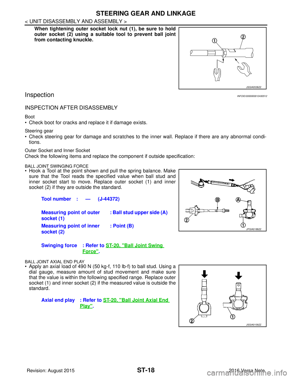
When tightening outer socket lock nut (1), be sure to hold
outer socket (2) using a suitable tool to prevent ball joint
from contacting knuckle.
InspectionINFOID:0000000012430512
INSPECTION AFTER DISASSEMBLY
Boot
• Check boot for cracks and replace it if damage exists.
Steering gear
• Check steering gear for damage and scratches to the inner wall. Replace if there are any abnormal condi- tions.
Outer Socket and Inner Socket
Check the following items and replace the component if outside specification:
BALL JOINT SWINGING FORCE• Hook a Tool at the point shown and pull the spring balance. Make
sure that the Tool reads the specified value when ball stud and
inner socket start to move. Replace outer socket (1) and inner
socket (2) if they are outside the standard.
BALL JOINT AXIAL END PLAY
• Apply an axial load of 490 N (50 kg-f, 110 lb-f) to ball stud. Using adial gauge, measure amount of stud movement and make sure
that the value is within the following specified range. Replace outer
socket (1) and inner socket (2) if the measured value is outside the
standard.
JSGIA0538ZZ
Tool number : — (J-44372)
Measuring point of outer
socket (1) : Ball stud upper side (A)
Measuring point of inner
socket (2) : Point (B)
Swinging force : Refer to ST-20, "
Ball Joint Swing
Force".
Axial end play : Refer to ST-20, "
Ball Joint Axial End
Play".
JPGIA0188ZZ
JSGIA0109ZZ
Revision: August 2015 2016 Versa Note
cardiagn.com
Page 3262 of 3641
![NISSAN NOTE 2016 Service Repair Manual CONTROL LINKAGETM-21
< REMOVAL AND INSTALLATION > [5MT: RS5F91R]
C
EF
G H
I
J
K L
M A
B
TM
N
O P
a. While pressing the lock of the selector cable in the direction of the arrows shown, remove the selec NISSAN NOTE 2016 Service Repair Manual CONTROL LINKAGETM-21
< REMOVAL AND INSTALLATION > [5MT: RS5F91R]
C
EF
G H
I
J
K L
M A
B
TM
N
O P
a. While pressing the lock of the selector cable in the direction of the arrows shown, remove the selec](/manual-img/5/57363/w960_57363-3261.png)
CONTROL LINKAGETM-21
< REMOVAL AND INSTALLATION > [5MT: RS5F91R]
C
EF
G H
I
J
K L
M A
B
TM
N
O P
a. While pressing the lock of the selector cable in the direction of the arrows shown, remove the selector cable from the shift
selector assembly.
b. While pressing the lock of the shifter cable in the direction of the arrows shown, remove the shifter cable from the shift selector
assembly.
10. Remove the shift selector assembly.
11. Remove center muffler, exhaust front tube, and heat plate. Refer to EX-5, "
Exploded View".
12. Remove the bracket from the vehicle.
13. Remove the grommet and then remove the shifter cable and selector cable from the vehicle.
INSTALLATION
Installation is in the reverse order of removal.
CAUTION:
• Install each cable without causing in terference with other parts. Do not allow cable to bend less than
120 mm (4.72 in), or exceed 180 degree twist.
• Install boot of each cable without causing interference with other parts. Do not exceed 90 degree twist.
• Fit boot to center console assembly an d the groove on shift selector handle.
• To install the shift selector handle, press it onto the shift selector. CAUTION:
• Do not reuse shift selector handle.
• Be careful with orientation of shift selector handle.
• Bolt hole is not threaded on new clutch housing. Self-tapping bolt is used to attach lock plate to clutch hous-
ing.
CAUTION:
Do not reuse self-tapping bolt.
• Insert each cable until it reaches the cable mounting bracket and shift selector assembly.
• Insert each cable until it reaches the shifter lever A and the selector lever.
• Move the shift selector to the neutral position.
InspectionINFOID:0000000012430956
INSPECTION AFTER INSTALLATION
Shift Selector Handle
Check that the shift selector handle is installed in the right position.
Shifter Cable and Selector Cable
• Pull each cable in the removal direction to check that it does not disconnect from the cable mounting
bracket.
• Pull each cable in the removal direction to check that it does not disconnect from the shift selector assembly.
• Pull grommet in the removal direction to che ck that it does not disconnect from the vehicle.
Shift Selector Assembly and Shift Selector
• Check that there is no unusual noise, binding, bending, looseness, and interference when the shift selector
is moved to each position. If there is a malfuncti on, then repair or replace the malfunctioning part.
• Check that the shift selector smoothl y returns to the neutral position after moving the shift selector from 1st
to 2nd gear and releasing it. If there is a malfunction, then repair or replace the malfunctioning part.
• Check that the shift selector smoothly returns to the neutral position after moving the shift selector from 5th to the reverse gear position and releasing it. If there is a malfunction, then repair or replace the malfunction-
ing part.
JPDIC0793ZZ
Revision: August 2015 2016 Versa Note
cardiagn.com