2016 NISSAN NOTE fuel type
[x] Cancel search: fuel typePage 1852 of 3641

WHEEL ALIGNMENTFSU-7
< PERIODIC MAINTENANCE >
C
DF
G H
I
J
K L
M A
B
FSU
N
O P
WHEEL ALIGNMENT
InspectionINFOID:0000000012430301
PRELIMINARY INSPECTION
WARNING:
Always adjust the wheel alignment with the vehicle on a flat surface.
NOTE:
If the wheel alignment is out of s pecification, inspect and replace any damaged or worn rear suspension parts
before making any adjustments.
1. Check and adjust the wheel alignment with the vehicle under unladen conditions. “Unladen conditions”
means that the fuel, engine coolant, and lubricants are full; the spare tire, jack, hand tools and mats are in
designated positions.
2. Check the tires for incorrect air pressure and excessive wear.
3. Check the wheels for run out and damage. Refer to WT-54, "
Wheel".
4. Check the wheel bearing axial end play. Refer to FAX-27, "
Wheel Bearing".
5. Check the shock absorbers for leaks or damage.
6. Check each mount point of the suspension co mponents for any excessive looseness or damage.
7. Check each link, arm, and the suspension member for any damage.
8. Check the vehicle height. Refer to FSU-21, "
Wheelarch Height (Unladen*)".
GENERAL INFORMATION AND RECOMMENDATIONS
1. A Four-Wheel Thrust Alignment should be performed.
• This type of alignment is recomm ended for any NISSAN/INFINITI vehicle.
• The four-wheel “thrust” process helps ensure that the vehicle is properly aligned and the steering wheel
is centered.
• The alignment machine itself should be capabl e of accepting any NISSAN/INFINITI vehicle.
• The alignment machine should be checked to ensure that it is level.
2. Make sure the alignment machine is properly calibrated. • Your alignment machine should be regularly calibrated in order to give correct information.
• Check with the manufacturer of your specific a lignment machine for their recommended Service/Cali-
bration Schedule.
ALIGNMENT PROCESS
IMPORTANT: Use only the alignment specifications listed in this Service Manual. Refer to FSU-20, "Wheel
Alignment (Unladen*1)".
• When displaying the alignment settings, many alignment machines use “indicators”: (Green/red, plus or
minus, Go/No Go). Do NOT use these indicators.
- The alignment specifications programmed into your alignment machine that operate these indicators may
not be correct.
- This may result in an ERROR.
• Most camera-type alignment machines are equipped with "Rolling Compensation" method and optional
"Jacking Compensation" method to "compensate" the alignment targets or head units.
"Rolling Compensation" is the preferred method.
- If using the "Rolling Compensation" method, after inst alling the alignment targets or head units, push or pull
on the rear wheel to move the vehicle. Do not push or pull on the vehicle body.
- If using the "Jacking Compensation" method, after inst alling the alignment targets or head units, raise the
vehicle and rotate the wheels 1/2 turn in either direction.
NOTE:
Do not use the "Rolling Compensation" method if you are using sensor-type alignment equipment.
• Follow all instructions for the alignment machine you're using for more information.
CAMBER, CASTER AND KINGPIN INCLINATION ANGLES INSPECTION
• Camber, caster, kingpin inclination angles cannot be adjusted.
• Before inspection, set the front wheels onto a turning radius gauge. Set the rear wheels onto a pad that has
the same height so the vehicle will remain horizontal.
TOTAL TOE-IN INSPECTION
Measure the total toe-in using the following procedure.
Revision: August 2015 2016 Versa Note
cardiagn.com
Page 1868 of 3641

FL-2
< PRECAUTION >
PRECAUTIONS
PRECAUTION
PRECAUTIONS
Precaution for Supplemental Restraint System (SRS) "AIR BAG" and "SEAT BELT
PRE-TENSIONER"
INFOID:0000000012432103
The Supplemental Restraint System such as “A IR BAG” and “SEAT BELT PRE-TENSIONER”, used along
with a front seat belt, helps to reduce the risk or severity of injury to the driver and front passenger for certain
types of collision. Information necessary to service the system safely is included in the SR and SB section of
this Service Manual.
WARNING:
• To avoid rendering the SRS inopera tive, which could increase the risk of personal injury or death in
the event of a collision which would result in air bag inflation, all maintenance must be performed by
an authorized NISSAN/INFINITI dealer.
• Improper maintenance, including in correct removal and installation of the SRS, can lead to personal
injury caused by unintent ional activation of the system. For re moval of Spiral Cable and Air Bag
Module, see the SR section.
• Do not use electrical test equipmen t on any circuit related to the SRS unless instructed to in this
Service Manual. SRS wiring harn esses can be identified by yellow and/or orange harnesses or har-
ness connectors.
PRECAUTIONS WHEN USING POWER TOOLS (AIR OR ELECTRIC) AND HAMMERS
WARNING:
• When working near the Airbag Diagnosis Sensor Unit or other Airbag System sensors with the Igni-
tion ON or engine running, DO NOT use air or electri c power tools or strike near the sensor(s) with a
hammer. Heavy vibration could activate the sensor( s) and deploy the air bag(s), possibly causing
serious injury.
• When using air or electric power tools or hammers , always switch the Ignition OFF, disconnect the
battery and wait at least three minutes before performing any service.
General PrecautionINFOID:0000000012432104
WARNING:
When replacing fuel line parts, be sure to observe the following.
• Put a “CAUTION: FLAMMABLE” sign in the work area.
• Be sure to work in a well ventilated area and have a CO
2 fire extinguisher.
• Do not smoke while working on the fuel system. Keep open flames and sparks away from the work
area.
CAUTION:
• Before removing fuel line parts, carry out the following procedures:
- Put drained fuel in an explosi on-proof container and put the lid on securely. Keep the container in
safe area.
- Release fuel pressure from the fuel lines. Refer to EC-1
37, "Work Procedure" .
- Disconnect the battery ground
cable.
• Always replace O-rings and clamps with new ones.
• Do not kink or twist tubes when they are being installed.
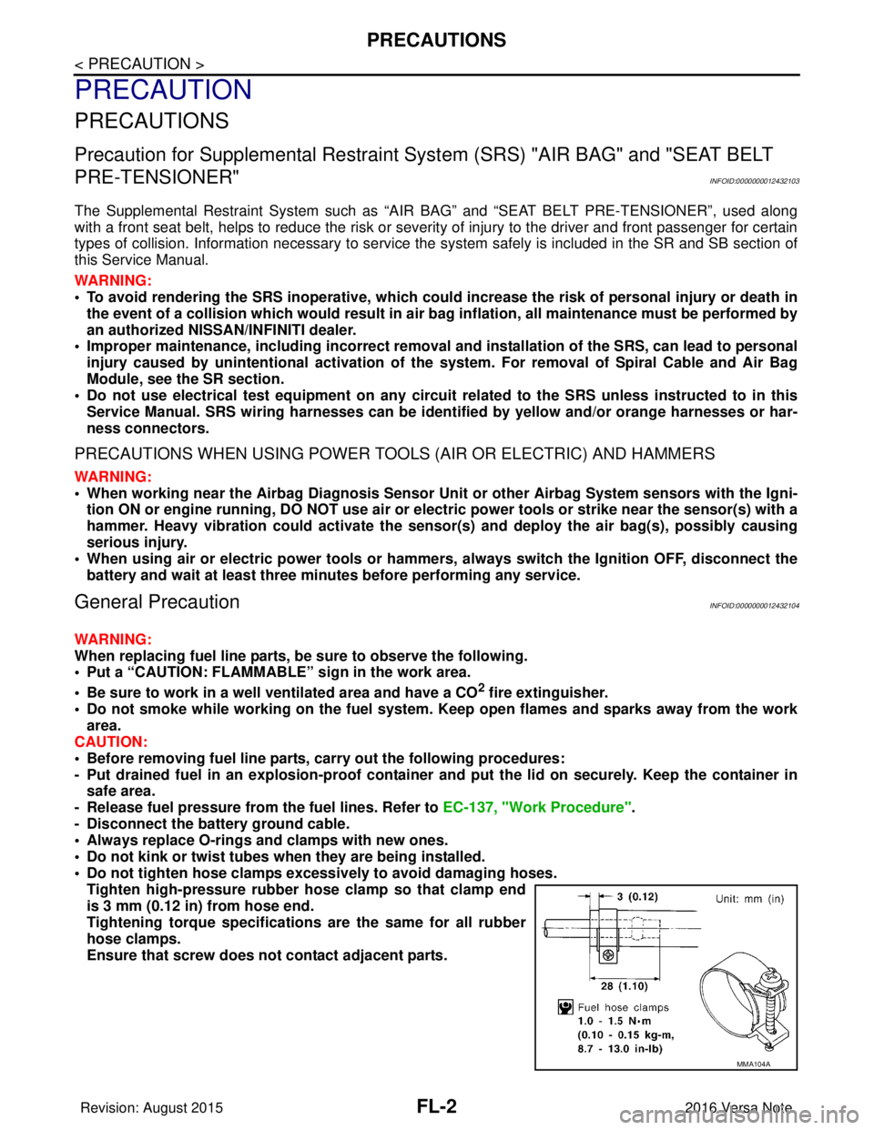
• Do not tighten hose clamps excessi vely to avoid damaging hoses.
Tighten high-pressure rubber hose clamp so that clamp end
is 3 mm (0.12 in) from hose end.
Tightening torque specificati ons are the same for all rubber
hose clamps.
Ensure that screw does not contact adjacent parts.
MMA104A
Revision: August 2015 2016 Versa Note
cardiagn.com
Page 2326 of 3641

RECOMMENDED FLUIDS AND LUBRICANTSMA-11
< PERIODIC MAINTENANCE >
C
DE
F
G H
I
J
K L
M B
MA
N
O A
RECOMMENDED FLUIDS AND LUBRICANTS
Fluids and LubricantsINFOID:0000000012432245
The following are approximate capacities. The actual capa
cities may be slightly different.When refilling, follow
the procedures described elsewhere in this manual.
Fluid type Capacity (Approximate)
Recommended Fluids/Lubricants
Metric US measure Imp measure
Fuel 41.0 10-7/8 gal
9 gal• Unleaded gasoline with an octane
rating of at least 87 AKI (RON 91)
Engine oil
Drain and refill With oil filter change
3.5 3-3/4 qt 3-1/8 qt
• Genuine NISSAN Engine Oil or
equivalent
• Engine oil with API Certification
Mark, Viscosity SAE 5W-30
• For additional information, see "Engine Oil Recommendation".
• As an alternative to this recom-
mended oil, SAE 5W-30 or SAE
10W-30 conventional petroleum
based oils may be used and meet
all specifications and require-
ments necessary to maintain the
New Vehicle Limited Warranty.
Without oil filter change
3.2 3-3/8 qt 2-7/8 qt
Dry engine (engine overhaul) 4.0 4-1/4 qt 3-1/2 qt
Engine cool-
ant With reser-
voir tank at
“MAX” level
CVT
7.3 7-3/4 qt 6-3/8 qt
• Pre-diluted Genuine NISSAN Long Life Anti-freeze / Coolant
(blue) or equivalent
M/T
6.7 7-1/8 qt 5-7/8 qt
Reservoir tank capacity
(at “MAX” level) 0.7
3/4 qt
5/8 qt
Manual transaxle fluid (MTF) 2.67 5-5/8 pt 4-3/4 pt • Genuine NISSAN
Manual Trans-
mission Fluid (MTF) HQ Multi
75W-85, or equivalent
• If Genuine NISSAN Manual
Transmission Fluid (MTF) HQ
Multi is not available, API GL-4,
Viscosity SAE 75W-85 may be
used as a temporary replacement.
However use Genuine NISSAN
Manual Transmission Fluid (MTF)
HQ Multi as soon as it is available.
CVT fluid 6.9 7-1/4 qt 6-1/8 qt • Genuine NISSAN CVT Fluid NS-3
• NISSAN recommends using Gen-
uine NISSAN CVT Fluid NS-3
ONLY in NISSAN CVTs. Do not
mix with other fluids. Using fluids
that are not equivalent to Genuine
NISSAN CVT Fluid NS-3 may
damage the CVT. Damage
caused by the use of fluids other
than as recommended is not cov-
ered under NISSAN's New Vehi-
cle Limited Warranty.
Brake and clutch fluid —— —• Genuine NISSAN Super Heavy
Duty Brake Fluid or equivalent
DOT 3 (US FMVSS No. 116)
• Available in mainland U.S.A.
through a NISSAN dealer.
Multi-purpose grease —— — NLGI No. 2 (Lithium soap base)
Windshield washer fluid 3.5 3-3/4 qt 3-1/8 qt • Genuine NISSAN Windshield
Washer Concentrate Cleaner &
Anti-Freeze or equivalent
Revision: August 2015 2016 Versa Note
cardiagn.com
Page 2327 of 3641

MA-12
< PERIODIC MAINTENANCE >
RECOMMENDED FLUIDS AND LUBRICANTS
Engine Oil Recommendation
INFOID:0000000012432246
NISSAN recommends the use of an energy conservi ng oil in order to improve fuel economy.
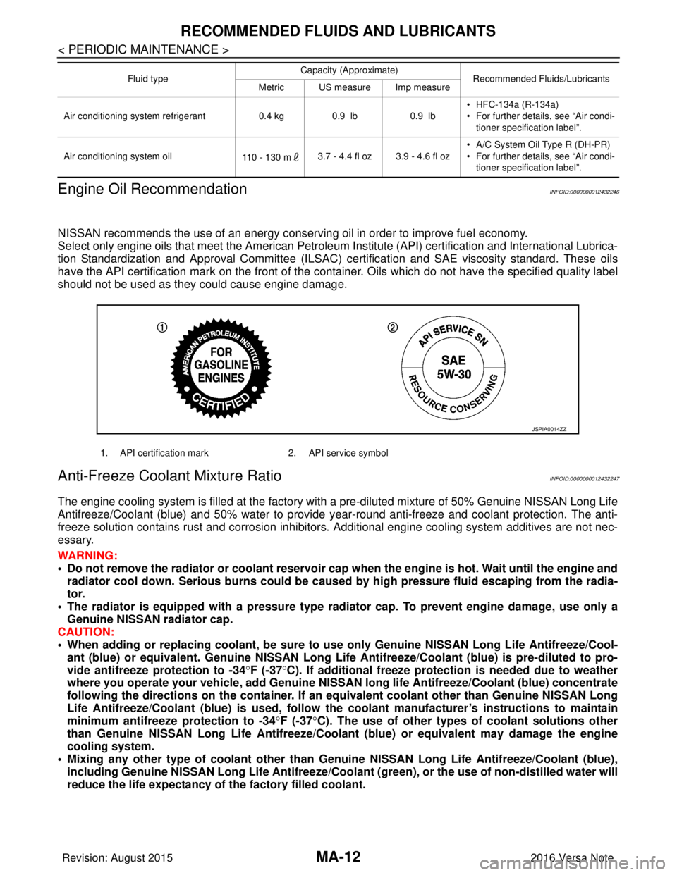
Select only engine oils that meet the American Petroleum Institute (API) certification and International Lubrica-
tion Standardization and Approval Committee (ILSAC) ce rtification and SAE viscosity standard. These oils
have the API certification mark on the front of the container. Oils whic h do not have the specified quality label
should not be used as they could cause engine damage.
Anti-Freeze Coolant Mixture RatioINFOID:0000000012432247
The engine cooling system is filled at the factory with a pre-diluted mixture of 50% Genuine NISSAN Long Life
Antifreeze/Coolant (blue) and 50% water to provide year-round anti-freeze and coolant protection. The anti-
freeze solution contains rust and corrosion inhibitors. Additional engine cooling system additives are not nec-
essary.
WARNING:
• Do not remove the radiator or coolant reservoir cap when the engine is hot. Wait until the engine and radiator cool down. Serious burns could be caused by high pressure fluid escaping from the radia-
tor.
• The radiator is equipped with a pressure type radiator cap. To prevent engine damage, use only a
Genuine NISSAN radiator cap.
CAUTION:
• When adding or replacing coolant, be sure to use only Genuine NISSAN Lo ng Life Antifreeze/Cool-
ant (blue) or equivalent. Genuine NISSAN Long Life Antifreeze/Coolant (blue) is pre-diluted to pro-
vide antifreeze protection to -34 °F (-37 °C). If additional freeze protect ion is needed due to weather
where you operate your vehicle, add Genuine NISSAN long life Antifreeze/Coolant (blue) concentrate
following the directions on the container. If an equivalent coolant other than Genuine NISSAN Long
Life Antifreeze/Coolant (blue) is used, follow the coolant manufact urer’s instructions to maintain
minimum antifreeze protection to -34 °F (-37 °C). The use of other types of coolant solutions other
than Genuine NISSAN Long Life Antifreeze/Coolant (blue) or equivalent may damage the engine
cooling system.
• Mixing any other type of coolant other than Genuine NISSAN Long Life Antifreeze/Coolant (blue),
including Genuine NISSAN Long Life Antifreeze/Coolant (green), or the use of non-distilled water will
reduce the life expectancy of the factory filled coolant.
Air conditioning system refrigerant 0.4 kg0.9 lb 0.9 lb• HFC-134a (R-134a)
• For further details, see “Air condi-
tioner specification label”.
Air conditioning system oil 110 - 130 m3.7 - 4.4 fl oz 3.9 - 4.6 fl oz • A/C System Oil Type R (DH-PR)
• For further details, see “Air condi-
tioner specification label”.
Fluid type
Capacity (Approximate)
Recommended Fluids/Lubricants
Metric US measure Imp measure
1. API certification mark 2. API service symbol
JSPIA0014ZZ
Revision: August 2015 2016 Versa Note
cardiagn.com
Page 2360 of 3641

MWI-2
U1010 CONTROL UNIT (CAN) .........................39
Description ........................................................... ...39
DTC Logic ...............................................................39
Diagnosis Procedure ..............................................39
B2205 VEHICLE SPEED ...................................40
Description ........................................................... ...40
DTC Logic ...............................................................40
Diagnosis Procedure .............................................40
B2267 ENGINE SPEED .....................................41
Description ........................................................... ...41
DTC Logic ...............................................................41
Diagnosis Procedure ..............................................41
B2268 WATER TEMP ........................................42
Description ........................................................... ...42
DTC Logic ...............................................................42
Diagnosis Procedure ..............................................42
POWER SUPPLY AND GROUND CIRCUIT .....43
COMBINATION METER ........................................ ...43
COMBINATION METER : Diagnosis Procedure ....43
BCM (BODY CONTROL MODULE) ...................... ...43
BCM (BODY CONTROL MODULE) : Diagnosis
Procedure ...............................................................
44
FUEL LEVEL SENSOR SIGNAL CIRCUIT .......45
Description ........................................................... ...45
Component Function Check ...................................45
Diagnosis Procedure .............................................45
Component Inspection ............................................46
WASHER FLUID LEVEL SWITCH CIRCUIT ....47
Description ........................................................... ...47
Diagnosis Procedure ..............................................47
Component Inspection ............................................47
SYMPTOM DIAGNOSIS .............................48
THE FUEL GAUGE INDICATOR DOES NOT
OPERATE ....................................................... ...
48
Description ........................................................... ...48
Diagnosis Procedure ..............................................48
THE OIL PRESSURE WARNING LAMP
DOES NOT TURN ON .......................................
49
Description ..............................................................49
Diagnosis Procedure ..............................................49
THE OIL PRESSURE WARNING LAMP
DOES NOT TURN OFF .....................................
50
Description ........................................................... ...50
Diagnosis Procedure ..............................................50
THE DOOR OPEN WARNING CONTINUES
DISPLAYING, OR DOES NOT DISPLAY ..........
51
Description ........................................................... ...51
Diagnosis Procedure ..............................................51
THE PARKING BRAKE RELEASE WARNING
CONTINUES DISPLAYING, OR DOES NOT
DISPLAY ............................................................
52
Description ........................................................... ...52
Diagnosis Procedure ...............................................52
THE LOW WASHER FLUID WARNING CON-
TINUES DISPLAYING, or DOES NOT DIS-
PLAY ..................................................................
53
Description ........................................................... ...53
Diagnosis Procedure ...............................................53
REMOVAL AND INSTALLATION ..............54
COMBINATION METER ................................. ...54
Removal and Installation .........................................54
TYPE B
HOW TO USE THIS MANU AL ...................
55
APPLICATION NOTICE ................................. ...55
Information ........................................................... ...55
PRECAUTION ............................................56
PRECAUTIONS .............................................. ...56
Precaution for Supplemental Restraint System
(SRS) "AIR BAG" and "SEAT BELT PRE-TEN-
SIONER" .............................................................. ...
56
PREPARATION ..........................................57
PREPARATION .............................................. ...57
Commercial Service Tools ................................... ...57
SYSTEM DESCRIPTION ...........................58
COMPONENT PARTS .................................... ...58
METER SYSTEM .......................................................58
METER SYSTEM : Component Parts Location ... ...58
METER SYSTEM : Combination Meter ..................59
SYSTEM ............................................................61
METER SYSTEM .......................................................61
METER SYSTEM : System Description ............... ...61
METER SYSTEM : Fail-safe ...................................62
SPEEDOMETER .................................................... ...63
SPEEDOMETER : System Description ..................63
TACHOMETER ....................................................... ...63
TACHOMETER : System Description .....................64
SHIFT POSITION INDICATOR .............................. ...64
SHIFT POSITION INDICATOR : System Descrip-
tion ....................................................................... ...
64
HIGH WATER TEMPERATURE WARNING LAMP ...64
HIGH WATER TEMPERATURE WARNING
LAMP : System Description ....................................
64
Revision: August 2015 2016 Versa Note
cardiagn.com
Page 2367 of 3641
![NISSAN NOTE 2016 Service Repair Manual MWI
COMPONENT PARTSMWI-9
< SYSTEM DESCRIPTION > [TYPE A]
C
D
E
F
G H
I
J
K L
M B A
O P
METER SYSTEM : Combination MeterINFOID:0000000012432542
The combination meter controls the following items a ccor NISSAN NOTE 2016 Service Repair Manual MWI
COMPONENT PARTSMWI-9
< SYSTEM DESCRIPTION > [TYPE A]
C
D
E
F
G H
I
J
K L
M B A
O P
METER SYSTEM : Combination MeterINFOID:0000000012432542
The combination meter controls the following items a ccor](/manual-img/5/57363/w960_57363-2366.png)
MWI
COMPONENT PARTSMWI-9
< SYSTEM DESCRIPTION > [TYPE A]
C
D
E
F
G H
I
J
K L
M B A
O P
METER SYSTEM : Combination MeterINFOID:0000000012432542
The combination meter controls the following items a ccording to the signals received from each unit via CAN
communication and the signals from switches and sensors:
• Measuring instruments
• Indicator lamps
• Warning lamps
• Meter illumination control
• Information display
ARRANGEMENT OF COMBINATION METER
6. ECM Transmits the following signals to the combination meter via CAN communication:
• Engine speed signal
• Engine coolant temperature signal
• Fuel consumption monitor signal
• Engine oil pressure sensor signal
Refer to EC-14, "
ENGINE CONTROL SYSTEM : ComponentPartsLocation" for de-
tailed installation location.
7. BCM Transmits the following signals to the combination meter via CAN communication:
• Door switch signal
• Buzzer signal
Refer to BCS-137, "
Removal and Installation" for detailed installation location.
8. Combination meter Refer to MWI-9, "
METER SYSTEM : Combination Meter".
9. Fuel level sensor unit and fuel pump
(fuel level sensor) Transmits the fuel level sensor signal to the combination meter.
No.
Component Function
U: USAEU: Except USA
AWNIA3633ZZ
Revision: August 2015 2016 Versa Note
cardiagn.com
Page 2368 of 3641
![NISSAN NOTE 2016 Service Repair Manual MWI-10
< SYSTEM DESCRIPTION >[TYPE A]
SYSTEM
SYSTEM
METER SYSTEM
METER SYSTEM : System DescriptionINFOID:0000000012432543
SYSTEM DIAGRAM
COMBINATION METER INPUT SIGNAL (CAN COMMUNICATION SIGNAL)
DESCR NISSAN NOTE 2016 Service Repair Manual MWI-10
< SYSTEM DESCRIPTION >[TYPE A]
SYSTEM
SYSTEM
METER SYSTEM
METER SYSTEM : System DescriptionINFOID:0000000012432543
SYSTEM DIAGRAM
COMBINATION METER INPUT SIGNAL (CAN COMMUNICATION SIGNAL)
DESCR](/manual-img/5/57363/w960_57363-2367.png)
MWI-10
< SYSTEM DESCRIPTION >[TYPE A]
SYSTEM
SYSTEM
METER SYSTEM
METER SYSTEM : System DescriptionINFOID:0000000012432543
SYSTEM DIAGRAM
COMBINATION METER INPUT SIGNAL (CAN COMMUNICATION SIGNAL)
DESCRIPTION
Combination Meter
• The combination meter receives necessary signals from each unit, switch, and sensor to control the follow-
ing functions.
- Measuring instruments
- Warning lamps
- Indicator lamps
- Meter illumination control
- Information display
• The combination meter incorporates a buzzer function that sounds an audible alarm with the integrated buzzer device. Refer to WCS-7, "
WARNING CHIME SYSTEM : System Description" for further details.
AWNIA3080GB
Transmit unit Signal name
ABS actuator and electric unit (c ontrol unit) Vehicle speed signal
BCM Door switch signal
Buzzer signal
TCM Shift position signal
ECM Engine speed signal
Engine coolant temperature signal
Engine oil pressure signal
Fuel consumption signal
Loose fuel cap signal
Revision: August 2015
2016 Versa Note
cardiagn.com
Page 2369 of 3641
![NISSAN NOTE 2016 Service Repair Manual MWI
SYSTEMMWI-11
< SYSTEM DESCRIPTION > [TYPE A]
C
D
E
F
G H
I
J
K L
M B A
O P
• The combination meter includes an on board diagnosis function.
• The combination meter can be diagnosed with CONSUL NISSAN NOTE 2016 Service Repair Manual MWI
SYSTEMMWI-11
< SYSTEM DESCRIPTION > [TYPE A]
C
D
E
F
G H
I
J
K L
M B A
O P
• The combination meter includes an on board diagnosis function.
• The combination meter can be diagnosed with CONSUL](/manual-img/5/57363/w960_57363-2368.png)
MWI
SYSTEMMWI-11
< SYSTEM DESCRIPTION > [TYPE A]
C
D
E
F
G H
I
J
K L
M B A
O P
• The combination meter includes an on board diagnosis function.
• The combination meter can be diagnosed with CONSULT.
METER CONTROL FUNCTION LIST
METER SYSTEM : Fail-safeINFOID:0000000012432544
The combination meter activates the fail-safe contro l if CAN communication with each unit is malfunctioning.
System DescriptionReference
Measuring instruments Speedometer
Indicates vehicle speed. MWI-12,
"SPEEDOME-
TER : System De-
scription"
Tachometer
Indicates engine speed. MWI-12, "
TA -
CHOMETER :
System Descrip-
tion"
Shift position indicator
Indicates shift position.MWI-13, "
SHIFT
POSITION INDI-
CATOR : System
Description"
Warning lamp/indicator
lamp
Engine oil pressure warning lamp The warning lamp turns ON or turns OFF,
according to engine hydraulic pressure. MWI-13, "
OIL
PRESSURE
WARNING LAMP
: System Descrip-
tion"
Meter illumination con-
trol
Meter illumination control function
Controls the back light of combination meter. MWI-13, "
METER
ILLUMINATION
CONTROL : Sys-
tem Description"
Information displayOdo/trip meter Indicates mileage.
MWI-14, "
INFOR-
MATION DIS-
PLAY : System
Description"
Engine coolant temperature gauge Indicates engine coolant temperature.
Fuel gaugeIndicates fuel level.
Loose fuel cap warning Indicates loose fuel cap.
Low fuel warning Indicates fuel level.
Trip computer Instant fuel consumption Displays current fuel consumption.
Average fuel consumption Displays average fuel consumption.
Distance to empty Displays distance to empty.
Travel distance
Displays mileage.
Function Specifications
Speedometer Reset to zero by suspending communication.
Tachometer
Illumination control When suspending communication, changes to nighttime mode.
Shift position indicator When suspending communication, not indicate.
Information display Trip com-
puterCurrent fuel consump-
tion
• When reception time of an abnormal signal is 2 seconds or
less, the last received datum is used for calculation to indi-
cate the result.
• When reception time of an abnormal signal is more than two
seconds, the last result calculated during normal condition is
indicated.
Average fuel consump-
tion
Distance to empty
Engine coolant temperature gauge Reset to zero by suspending communication.
Odo/trip meter An indicated value is maintained at communications blackout.
Buzzer The buzzer turns OFF by suspending communication.
Revision: August 2015 2016 Versa Note
cardiagn.com