2016 NISSAN NOTE steering
[x] Cancel search: steeringPage 1860 of 3641
FRONT SUSPENSION MEMBERFSU-15
< UNIT REMOVAL AND INSTALLATION >
C
DF
G H
I
J
K L
M A
B
FSU
N
O P
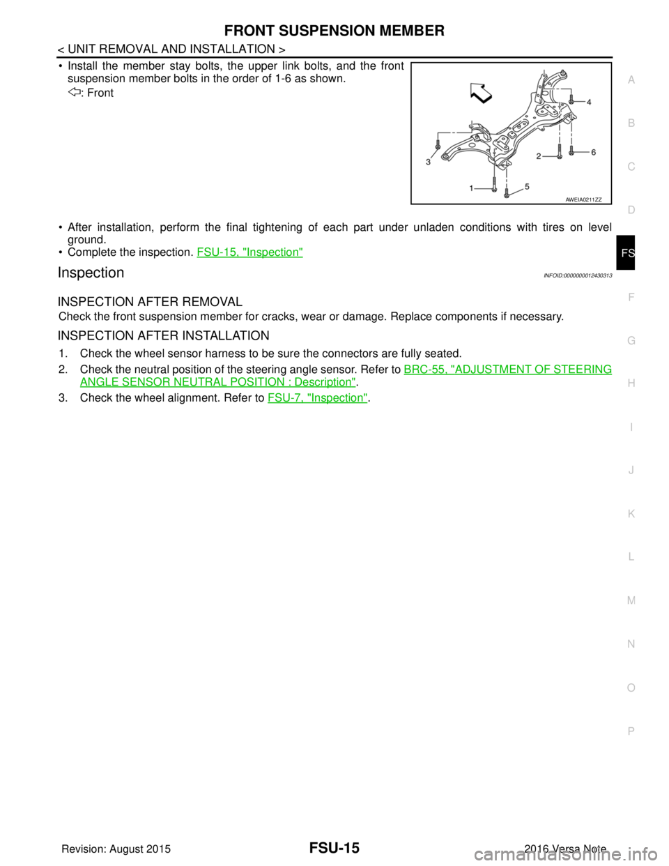
• Install the member stay bolts, the upper link bolts, and the front suspension member bolts in the order of 1-6 as shown.
: Front
• After installation, perform the final tightening of each part under unladen conditions with tires on level
ground.
• Complete the inspection. FSU-15, "
Inspection"
InspectionINFOID:0000000012430313
INSPECTION AFTER REMOVAL
Check the front suspension member for cracks, wear or damage. Replace components if necessary.
INSPECTION AFTER INSTALLATION
1. Check the wheel sensor harness to be sure the connectors are fully seated.
2. Check the neutral position of the steering angle sensor. Refer to BRC-55, "
ADJUSTMENT OF STEERING
ANGLE SENSOR NEUTRAL POSITION : Description".
3. Check the wheel alignment. Refer to FSU-7, "
Inspection".
AWEIA0211ZZ
Revision: August 2015 2016 Versa Note
cardiagn.com
Page 1864 of 3641
FRONT COIL SPRING AND STRUTFSU-19
< UNIT DISASSEMBLY AND ASSEMBLY >
C
DF
G H
I
J
K L
M A
B
FSU
N
O P
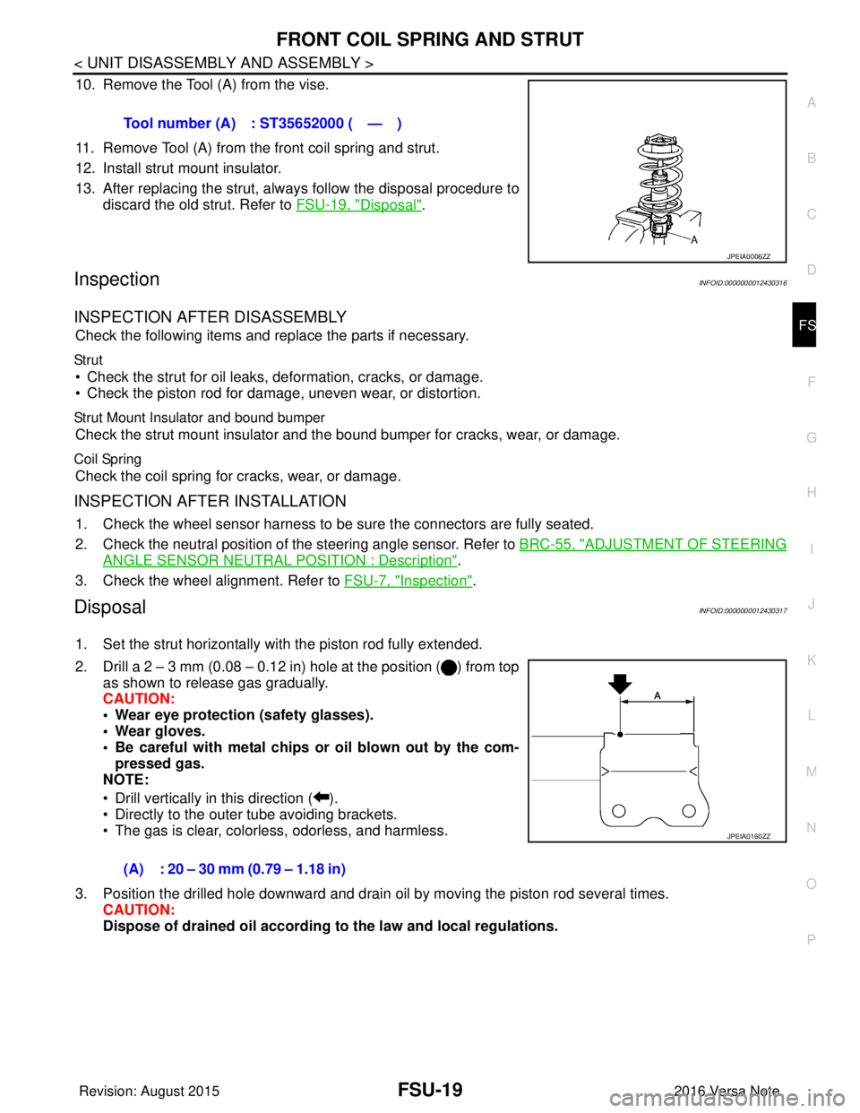
10. Remove the Tool (A) from the vise.
11. Remove Tool (A) from the front coil spring and strut.
12. Install strut mount insulator.
13. After replacing the strut, always follow the disposal procedure to discard the old strut. Refer to FSU-19, "
Disposal".
InspectionINFOID:0000000012430316
INSPECTION AFTER DISASSEMBLY
Check the following items and replace the parts if necessary.
Str ut
• Check the strut for oil leaks, deformation, cracks, or damage.
• Check the piston rod for damage, uneven wear, or distortion.
Strut Mount Insulator and bound bumper
Check the strut mount insulator and t he bound bumper for cracks, wear, or damage.
Coil Spring
Check the coil spring for cracks, wear, or damage.
INSPECTION AFTER INSTALLATION
1. Check the wheel sensor harness to be sure the connectors are fully seated.
2. Check the neutral position of the steering angle sensor. Refer to BRC-55, "
ADJUSTMENT OF STEERING
ANGLE SENSOR NEUTRAL POSITION : Description".
3. Check the wheel alignment. Refer to FSU-7, "
Inspection".
DisposalINFOID:0000000012430317
1. Set the strut horizontally with the piston rod fully extended.
2. Drill a 2 – 3 mm (0.08 – 0.12 in) hole at the position ( ) from top
as shown to release gas gradually.
CAUTION:
• Wear eye protection (safety glasses).
• Wear gloves.
• Be careful with metal chips or oil blown out by the com-
pressed gas.
NOTE:
• Drill vertically in this direction ( ).
• Directly to the outer tube avoiding brackets.
• The gas is clear, colorless, odorless, and harmless.
3. Position the drilled hole downward and drain oil by moving the piston rod several times. CAUTION:
Dispose of drained oil according to the law and local regulations.
Tool number (A) : ST35652000 ( — )
JPEIA0006ZZ
(A) : 20 – 30 mm (0.79 – 1.18 in)
JPEIA0160ZZ
Revision: August 2015
2016 Versa Note
cardiagn.com
Page 1903 of 3641

ABBREVIATIONSGI-15
< HOW TO USE THIS MANUAL >
C
DE
F
G H
I
J
K L
M B
GI
N
O P
E
F
G
H
DLC Data link connector
DTC Diagnostic trouble code
ABBREVIATION DESCRIPTION
E/T Exhaust temperature
EBD Electric brake force distribution
EC Engine control
ECL Engine coolant level
ECM Engine control module
ECT Engine coolant temperature
ECV Electrical control valve
EEPROM Electrically erasable programmable read only memory EFT Engine fuel temperature
EGR Exhaust gas recirculation
EGRT Exhaust gas recirculation temperature EGT Exhaust gas temperature
EOP Engine oil pressure
EP Exhaust pressure
EPR Exhaust pressure regulator
EPS Electronically controlled power steering
ESP Electronic stability program system
EVAP canister Evaporative emission canister EVSE Electric vehicle supply equipment
EXC Exhaust control
ABBREVIATION DESCRIPTION
FC Fan control
FCW Forward collision warning
FIC Fuel injector control
FP Fuel pump
FR Front
FRP Fuel rail pressure
FRT Fuel rail temperature
FTP Fuel tank pressure
FTT Fuel tank temperature
ABBREVIATION DESCRIPTION
GND Ground
GPS Global positioning system
GST Generic scan tool
ABBREVIATION DESCRIPTION
HBMC Hydraulic body-motion control system HDD Hard disk drive
HO2S Heated oxygen sensor
ABBREVIATION
DESCRIPTION
Revision: August 2015 2016 Versa Note
cardiagn.com
Page 1905 of 3641

ABBREVIATIONSGI-17
< HOW TO USE THIS MANUAL >
C
DE
F
G H
I
J
K L
M B
GI
N
O P
O
P
R
S
T
ABBREVIATION DESCRIPTION
O2 Oxygen
O2S Oxygen sensor
OBD On board diagnostic
OC Oxidation catalytic converter
OD Overdrive
OL Open loop
OSS Output shaft speed
ABBREVIATION DESCRIPTION
P/S Power steering
PBR Potentio balance resistor
PCV Positive crankcase ventilation
PNP Park/Neutral position
PSP Power steering pressure
PTC Positive temperature coefficient
PTO Power takeoff
PWM Pulse width modulation
ABBREVIATION DESCRIPTION
RAM Random access memory
RAS Rear active steer
RH Right-hand
RHD Right-hand drive
ROM Read only memory
RPM Engine speed
RR Rear
ABBREVIATION DESCRIPTION
SAE Society of Automoti ve Engineers, Inc.
SCK Serial clock
SDS Service Data and Specifications
SRT System readiness test
SST Special Service Tools
ABBREVIATION DESCRIPTION
TC Turbocharger
TCM Transmission control module
TCS Traction control system
TCU Telematics communication unit
TP Throttle position
TPMS Tire pressure monitoring system TSS Turbine shaft speed
TWC Three way catalytic converter
Revision: August 2015 2016 Versa Note
cardiagn.com
Page 1919 of 3641
TOW TRUCK TOWINGGI-31
< PRECAUTION >
C
DE
F
G H
I
J
K L
M B
GI
N
O PTOW TRUCK TOWING
To w T r u c k To w i n gINFOID:0000000012433173
CAUTION:
• Never tow a CVT model with the rear wheels raised and the front wheels on the ground. This may
cause serious and expensive damage to the transaxle. If it is necessary to tow the vehicle with the
rear wheels raised, always use towin g dollies under the front wheels.
• Never tow a CVT model from the rear (that is b ackward) with four wheels on the ground. This may
cause serious and expensive damage to the transaxle.
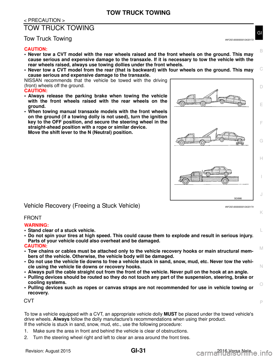
NISSAN recommends that the vehicle be towed with the driving
(front) wheels off the ground.
CAUTION:
• Always release the parking br ake when towing the vehicle
with the front wheels raised with the rear wheels on the
ground.
• When towing manual transaxle models with the front wheels on the ground (if a towing dolly is not used), turn the ignition
key to the OFF position, and secu re the steering wheel in the
straight-ahead position with a rope or similar device.
Move the shift lever to th e N (Neutral) position.
Vehicle Recovery (Freeing a Stuck Vehicle)INFOID:0000000012433174
FRONT
WARNING:
• Stand clear of a stuck vehicle.
• Do not spin your tires at high speed. This could cause them to explode and result in serious injury.
Parts of your vehicle could also overheat and be damaged.
CAUTION:
• Tow chains or cables must be attached only to the vehicle recovery hooks or main structural mem-
bers of the vehicle. Otherwise, the vehicle body will be damaged.
• Do not use the vehicle tie downs to free a vehicle stuck in sand, snow, mud, etc. Never tow the vehi-
cle using the vehicle tie downs or recovery hooks.
• Always pull the cable straight out from the front of the vehicle. Never pull on the hook at an angle.
• Pulling devices should be routed so they do not touch any part of the suspension, steering, brake or
cooling systems.
• Pulling devices such as ropes or canvas straps ar e not recommended for use in vehicle towing or
recovery.
CVT
To tow a vehicle equipped with a CVT, an appropriate vehicle dolly MUST be placed under the towed vehicle's
drive wheels. Always follow the dolly manufacture's re commendations when using their product.
If the vehicle is stuck in sand, snow , mud, etc., use the following procedure:
1. Make sure the area in front and behind the vehicle is clear of obstructions.
2. Turn the steering wheel right and left to clear an area around the front tires.
SGI986
Revision: August 2015 2016 Versa Note
cardiagn.com
Page 2058 of 3641
HEATING AND COOLING UNIT ASSEMBLYHA-33
< REMOVAL AND INSTALLATION >
C
DE
F
G H
J
K L
M A
B
HA
N
O P
HEATING AND COOLING UNIT ASSEMBLY
Exploded ViewINFOID:0000000012432018
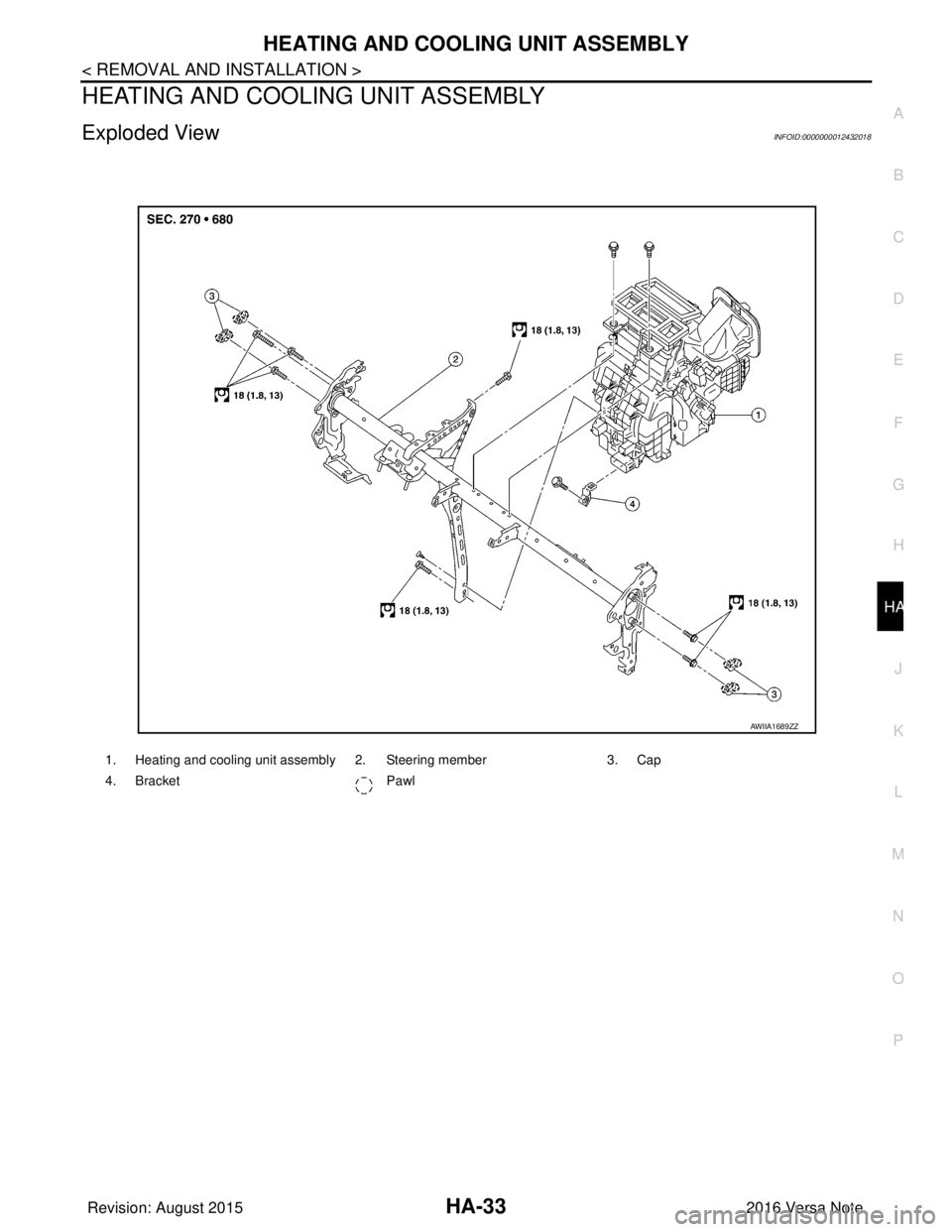
1. Heating and cooling unit assembly 2. Steering member 3. Cap
4. Bracket Pawl
AWIIA1689ZZ
Revision: August 2015 2016 Versa Note
cardiagn.com
Page 2060 of 3641
HEATING AND COOLING UNIT ASSEMBLYHA-35
< REMOVAL AND INSTALLATION >
C
DE
F
G H
J
K L
M A
B
HA
N
O P
5. Disconnect heater hoses from heater core.
6. Remove instrument panel assembly. Refer to IP-15, "
Removal and Installation".
7. Disconnect evaporator drain hose from heating and cooling unit assembly.
8. Disconnect harness connectors, grounds, retainers, etc. , and remove bolts required to remove steering
member.
9. Remove steering member and heating and cooling unit assembly.
10. Remove heating and cooling unit assembly from steering member. Refer to HA-33, "
Exploded View".
INSTALLATION
Installation is in the reverse order of removal.
CAUTION:
• Do not reuse O-rings.
• Apply compressor oil to new O-rings of the low-pressure flexible hose and high-pressure pipe for
installation.
• After charging refrigerant, check for leaks. Refer to HA-18, "
Leak Test".
NOTE:
When refilling engine coolant, refer to CO-9, "
Refilling".
HEATER CORE
HEATER CORE : Removal and InstallationINFOID:0000000012432020
REMOVAL
1. Remove the heating and cooling unit assembly. Refer to HA-34, "HEATING AND COOLING UNIT
ASSEMBLY : Removal and Installation".
2. Remove foot duct (LH). Refer to VTL-7, "
FOOT DUCT : Removal and Installation".
3. Remove heater packing.
4. Remove heater pipe flange.
5. Remove heater core.
INSTALLATION
Installation is in the reverse order of removal.
NOTE:
When refilling engine coolant, refer to CO-9, "
Refilling".
EVAPORATOR
EVAPORATOR : Removal and InstallationINFOID:0000000012432021
REMOVAL
1. Remove heating and cooling unit assembly. Refer to HA-34, "HEATING AND COOLING UNIT ASSEM-
BLY : Removal and Installation".
2. Remove foot duct (RH). Refer to VTL-7, "
FOOT DUCT : Removal and Installation".
3. Remove intake case. Refer to HA-33, "
Exploded View".
4. Remove expansion valve. Refer to HA-36, "
EXPANSION VALVE : Removal and Installation".
5. Remove evaporator cover and evaporator assembly.
INSTALLATION
Installation is in the reverse order of removal.
CAUTION:
• Do not reuse O-rings.
• Apply compressor oil to ne w O-rings for installation.
• Perform oil adjusting procedure afte r installing new evaporator. Refer to HA-22, "
Oil Adjusting Pro-
cedure for Components Replacement Except Compressor".
• After charging refrigerant, check for leaks. Refer to HA-18, "
Leak Test".
EXPANSION VALVE
Revision: August 2015 2016 Versa Note
cardiagn.com
Page 2069 of 3641

IP-1
BODY INTERIOR
C
DE
F
G H
I
K L
M
SECTION IP
A
B
IP
N
O P
CONTENTS
INSTRUMENT PANEL
PRECAUTION ....... ........................................2
PRECAUTIONS .............................................. .....2
Precaution for Supplemental Restraint System
(SRS) "AIR BAG" and "SEAT BELT PRE-TEN-
SIONER" ............................................................. ......
2
Precaution for Work ..................................................2
PREPARATION ............................................3
PREPARATION .............................................. .....3
Special Service Tools ........................................ ......3
Commercial Service Tools .......................................3
CLIP LIST ............................................................4
Descriptions for Clips ................................................4
SYMPTOM DIAGNOSIS ...............................8
SQUEAK AND RATTLE TROUBLE DIAG-
NOSES ........................ ........................................
8
Work Flow ........................................................... ......8
Generic Squeak and Rattle Troubleshooting ............9
Diagnostic Worksheet .............................................12
REMOVAL AND INSTALLATION ...............14
INSTRUMENT PANEL ASSEMBLY .............. ....14
Exploded View .................................................... ....14
Removal and Installation ..................................... ....15
STEERING COLUMN COVERS .......................17
Removal and Installation .........................................17
CENTER CONSOLE ASSEMBLY ....................18
Exploded View .........................................................18
Removal and Installation .........................................18
CENTER CONSOLE LOWER ...........................20
Removal and Installation .........................................20
CLUSTER LID A ...............................................21
Removal and Installation .........................................21
CLUSTER LID C ...............................................22
Removal and Installation .........................................22
FRONT AIR CONTROL FINISHER ...................23
Removal and Installation .........................................23
INSTRUMENT LOWER PANEL LH ..................24
Removal and Installation .........................................24
GLOVE BOX ASSEMBLY ................................25
Removal and Installation .........................................25
UPPER GLOVE BOX ........................................26
Removal and Installation ..................................... ....26
Revision: August 2015 2016 Versa Note
cardiagn.com