Page 633 of 3641
CLUTCH FLUIDCL-7
< PERIODIC MAINTENANCE >
CEF
G H
I
J
K L
M A
B
CL
N
O P
CLUTCH FLUID
InspectionINFOID:0000000012432216
CLUTCH FLUID LEAKS
• Check clutch line for cracks, deterioration or other damage. Replace any damaged parts.
• Check for clutch fluid leaks by fully depressing clutch pedal while engine is running. CAUTION:
If leaks occur around connections, reinstall th e lines or replace damaged parts, if necessary.
CLUTCH FLUID LEVEL
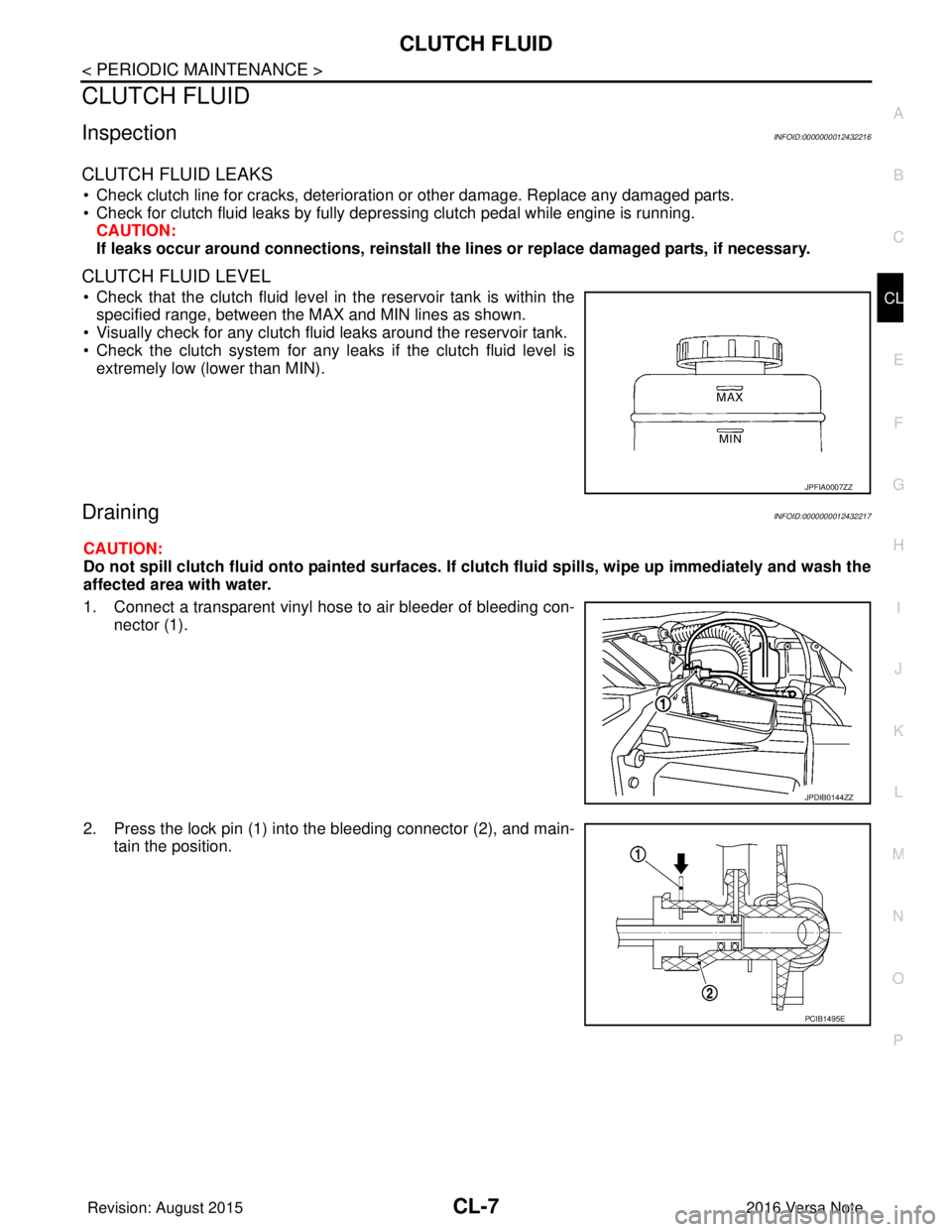
• Check that the clutch fluid level in the reservoir tank is within the
specified range, between the MAX and MIN lines as shown.
• Visually check for any clutch fluid leaks around the reservoir tank.
• Check the clutch system for any leaks if the clutch fluid level is
extremely low (lower than MIN).
DrainingINFOID:0000000012432217
CAUTION:
Do not spill clutch fluid onto painted surfaces. If clutch fluid spills, wipe up immediately and wash the
affected area with water.
1. Connect a transparent vinyl hose to air bleeder of bleeding con-
nector (1).
2. Press the lock pin (1) into the bleeding connector (2), and main- tain the position.
JPFIA0007ZZ
JPDIB0144ZZ
PCIB1495E
Revision: August 2015 2016 Versa Note
cardiagn.com
Page 634 of 3641
CL-8
< PERIODIC MAINTENANCE >
CLUTCH FLUID
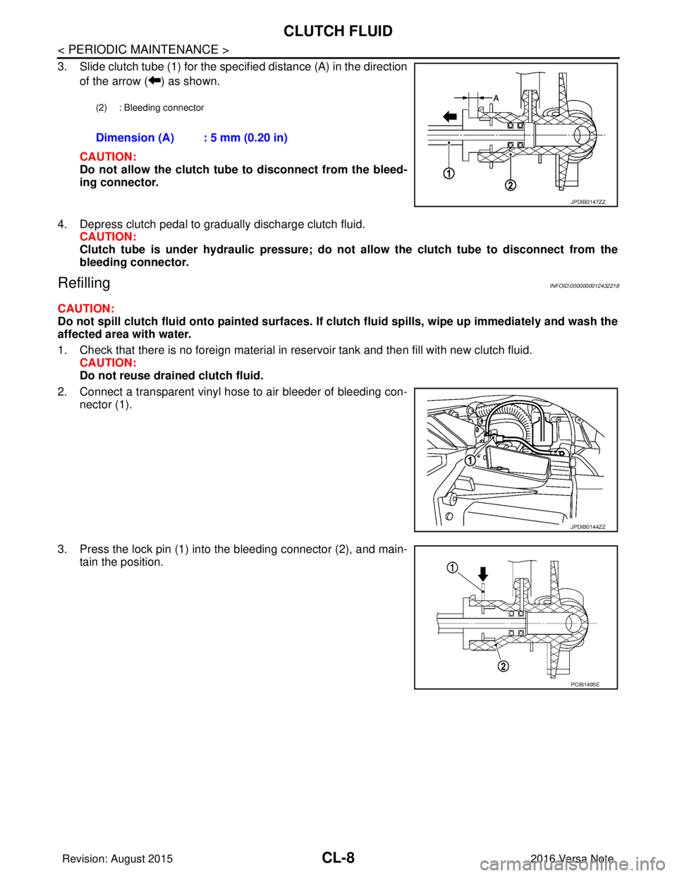
3. Slide clutch tube (1) for the specified distance (A) in the directionof the arrow ( ) as shown.
CAUTION:
Do not allow the clutch tube to disconnect from the bleed-
ing connector.
4. Depress clutch pedal to gradually discharge clutch fluid. CAUTION:
Clutch tube is under hydraulic pressure; do not allow the clutch tube to disconnect from the
bleeding connector.
RefillingINFOID:0000000012432218
CAUTION:
Do not spill clutch fluid onto painted surfaces. If cl utch fluid spills, wipe up immediately and wash the
affected area with water.
1. Check that there is no foreign material in reservoir tank and then fill with new clutch fluid. CAUTION:
Do not reuse drained clutch fluid.
2. Connect a transparent vinyl hose to air bleeder of bleeding con- nector (1).
3. Press the lock pin (1) into the bleeding connector (2), and main- tain the position.
(2) : Bleeding connector
Dimension (A) : 5 mm (0.20 in)
JPDIB0147ZZ
JPDIB0144ZZ
PCIB1495E
Revision: August 2015 2016 Versa Note
cardiagn.com
Page 635 of 3641
CLUTCH FLUIDCL-9
< PERIODIC MAINTENANCE >
CEF
G H
I
J
K L
M A
B
CL
N
O P
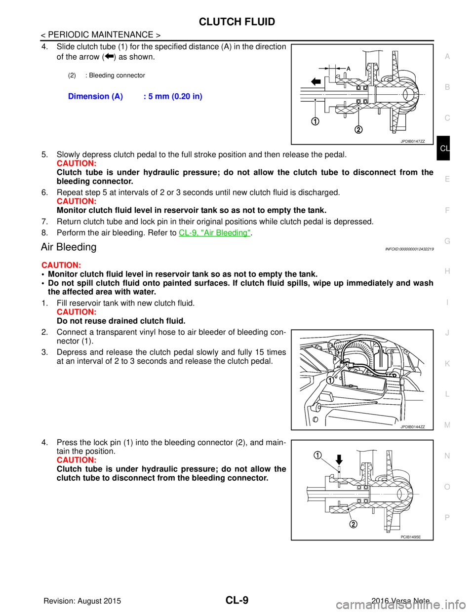
4. Slide clutch tube (1) for the specified distance (A) in the direction of the arrow ( ) as shown.
5. Slowly depress clutch pedal to the full stroke position and then release the pedal. CAUTION:
Clutch tube is under hydraulic pressure; do not allow the clutch tube to disconnect from the
bleeding connector.
6. Repeat step 5 at intervals of 2 or 3 seconds until new clutch fluid is discharged. CAUTION:
Monitor clutch fluid level in reservoir tank so as not to empty the tank.
7. Return clutch tube and lock pin in their original positions while clutch pedal is depressed.
8. Perform the air bleeding. Refer to CL-9, "
Air Bleeding".
Air BleedingINFOID:0000000012432219
CAUTION:
• Monitor clutch fluid level in reservoir tank so as not to empty the tank.
• Do not spill clutch fluid onto painted surfaces. If clutch fluid spil ls, wipe up immediately and wash
the affected area with water.
1. Fill reservoir tank with new clutch fluid. CAUTION:
Do not reuse drained clutch fluid.
2. Connect a transparent vinyl hose to air bleeder of bleeding con- nector (1).
3. Depress and release the clutch pedal slowly and fully 15 times at an interval of 2 to 3 seconds and release the clutch pedal.
4. Press the lock pin (1) into the bleeding connector (2), and main- tain the position.
CAUTION:
Clutch tube is under hydraulic pressure; do not allow the
clutch tube to disconnect from the bleeding connector.
(2) : Bleeding connector
Dimension (A) : 5 mm (0.20 in)
JPDIB0147ZZ
JPDIB0144ZZ
PCIB1495E
Revision: August 2015 2016 Versa Note
cardiagn.com
Page 643 of 3641
CSC (CONCENTRIC SLAVE CYLINDER)CL-17
< UNIT REMOVAL AND INSTALLATION >
CEF
G H
I
J
K L
M A
B
CL
N
O P
UNIT REMOVAL AND INSTALLATION
CSC (CONCENTRIC SLAVE CYLINDER)
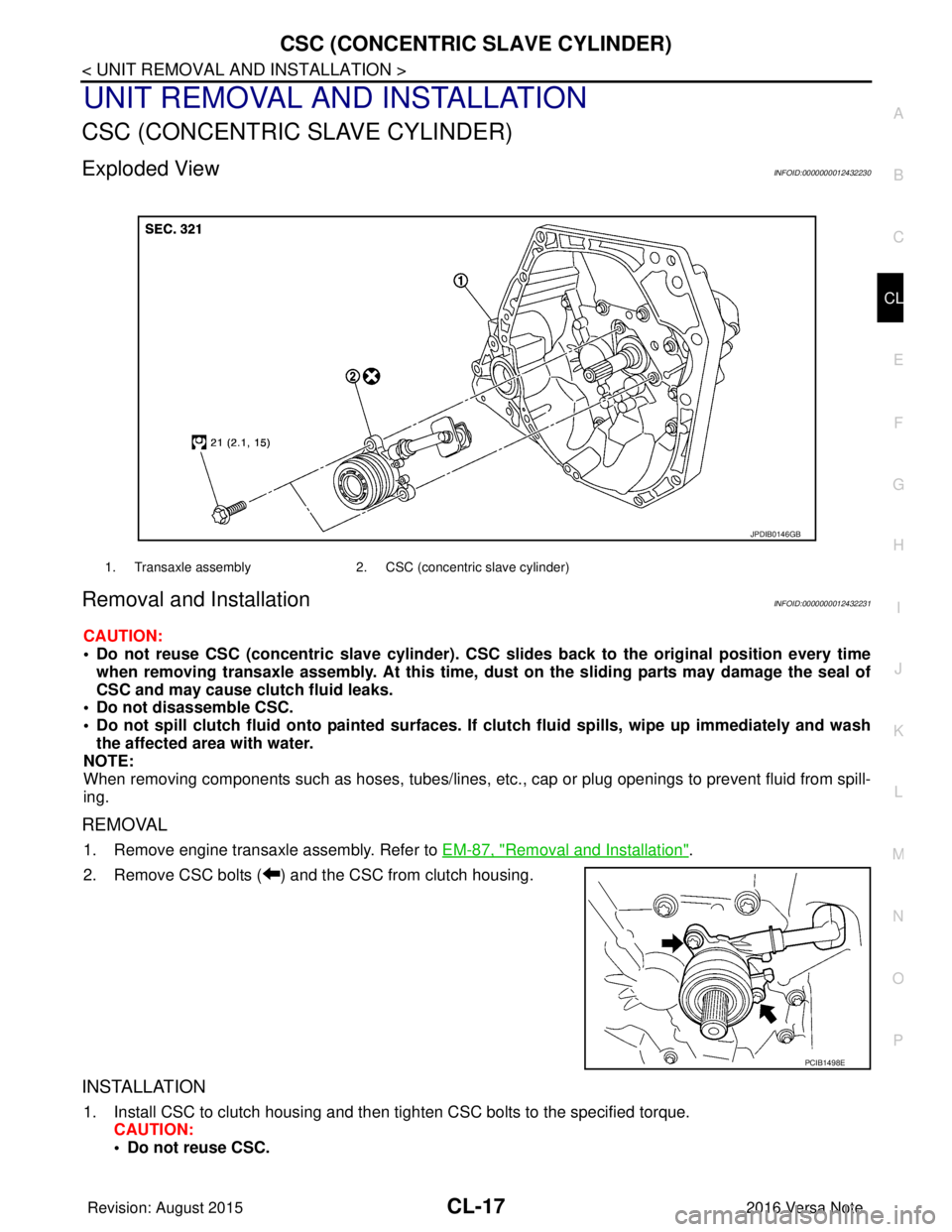
Exploded ViewINFOID:0000000012432230
Removal and InstallationINFOID:0000000012432231
CAUTION:
• Do not reuse CSC (concentric slave cylinder). CSC slides back to the original position every time
when removing transaxle assembly. At this time, du st on the sliding parts may damage the seal of
CSC and may cause clutch fluid leaks.
• Do not disassemble CSC.
• Do not spill clutch fluid onto pa inted surfaces. If clutch fluid spills, wipe up immediately and wash
the affected area with water.
NOTE:
When removing components such as hoses, tubes/lines, etc. , cap or plug openings to prevent fluid from spill-
ing.
REMOVAL
1. Remove engine transaxle assembly. Refer to EM-87, "Removal and Installation".
2. Remove CSC bolts ( ) and the CSC from clutch housing.
INSTALLATION
1. Install CSC to clutch housing and then tighten CSC bolts to the specified torque. CAUTION:
• Do not reuse CSC.
1. Transaxle assembly 2. CSC (concentric slave cylinder)
JPDIB0146GB
PCIB1498E
Revision: August 2015 2016 Versa Note
cardiagn.com
Page 644 of 3641
CL-18
< UNIT REMOVAL AND INSTALLATION >
CSC (CONCENTRIC SLAVE CYLINDER)
• Do not insert and operate CSC when transaxle is removed. Piston and stopper of CSC compo-nents may fall off.
2. Install engine and transaxle assembly. Refer to EM-87, "
Removal and Installation".
Inspection and AdjustmentINFOID:0000000012432232
INSPECTION AFTER INSTALLATION
Check for clutch fluid leaks and clutch fluid level. Refer to CL-7, "Inspection".
ADJUSTMENT AFTER INSTALLATION
Perform the air bleeding. Refer to CL-9, "Air Bleeding".
Revision: August 2015 2016 Versa Note
cardiagn.com
Page 645 of 3641
CLUTCH DISC AND CLUTCH COVERCL-19
< UNIT REMOVAL AND INSTALLATION >
CEF
G H
I
J
K L
M A
B
CL
N
O P
CLUTCH DISC AND CLUTCH COVER
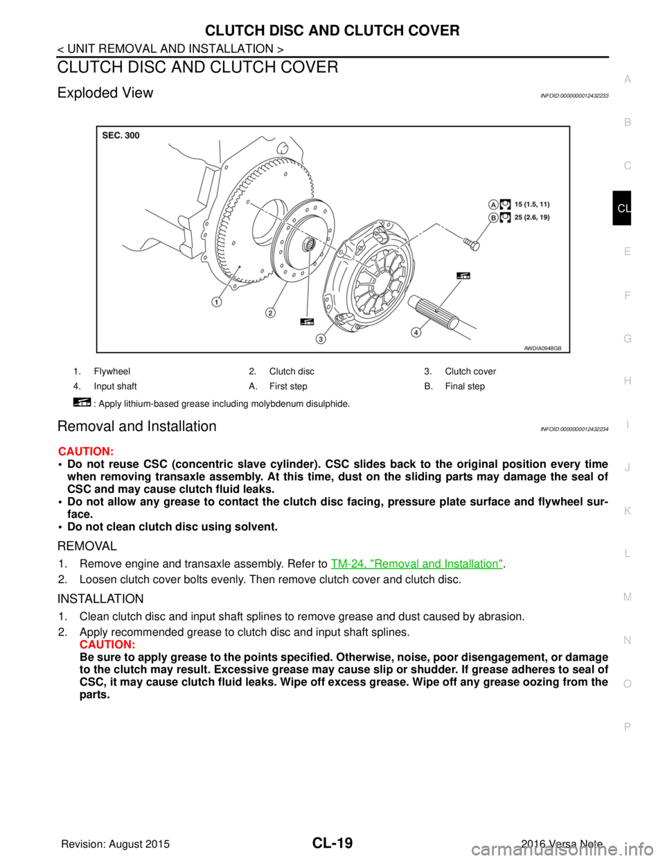
Exploded ViewINFOID:0000000012432233
Removal and InstallationINFOID:0000000012432234
CAUTION:
• Do not reuse CSC (concentric slave cylinder). CSC slides back to the original position every time
when removing transaxle assembly. At this time, du st on the sliding parts may damage the seal of
CSC and may cause clutch fluid leaks.
• Do not allow any grease to contact the clutch di sc facing, pressure plate surface and flywheel sur-
face.
• Do not clean clutch disc using solvent.
REMOVAL
1. Remove engine and transaxle assembly. Refer to TM-24, "Removal and Installation".
2. Loosen clutch cover bolts evenly. Then remove clutch cover and clutch disc.
INSTALLATION
1. Clean clutch disc and input shaft splines to remove grease and dust caused by abrasion.
2. Apply recommended grease to clutch disc and input shaft splines. CAUTION:
Be sure to apply grease to the points specified. Otherwise, noise, poor disengagement, or damage
to the clutch may result. Excessi ve grease may cause slip or shudder. If grease adheres to seal of
CSC, it may cause clutch fluid leaks. Wipe off excess grease. Wipe off any grease oozing from the
parts.
1. Flywheel 2. Clutch disc3. Clutch cover
4. Input shaft A. First stepB. Final step
: Apply lithium-based grease including molybdenum disulphide.
AWDIA0948GB
Revision: August 2015 2016 Versa Note
cardiagn.com
Page 646 of 3641
CL-20
< UNIT REMOVAL AND INSTALLATION >
CLUTCH DISC AND CLUTCH COVER
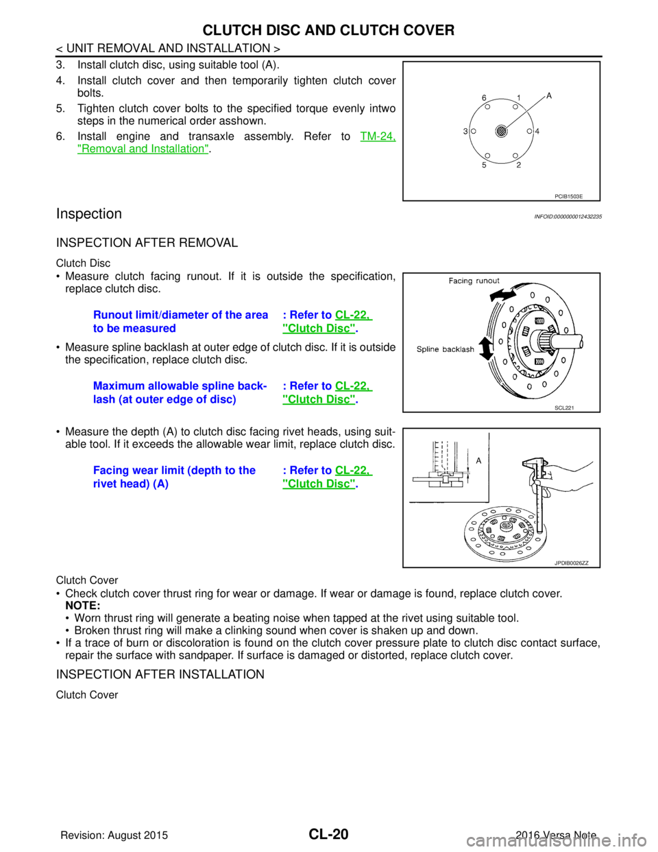
3. Install clutch disc, using suitable tool (A).
4. Install clutch cover and then temporarily tighten clutch coverbolts.
5. Tighten clutch cover bolts to the specified torque evenly intwo steps in the numerical order asshown.
6. Install engine and transaxle assembly. Refer to TM-24,
"Removal and Installation".
InspectionINFOID:0000000012432235
INSPECTION AFTER REMOVAL
Clutch Disc
• Measure clutch facing runout. If it is outside the specification,
replace clutch disc.
• Measure spline backlash at outer edge of clutch disc. If it is outside the specification, replace clutch disc.
• Measure the depth (A) to clutch disc facing rivet heads, using suit- able tool. If it exceeds the allowable wear limit, replace clutch disc.
Clutch Cover
• Check clutch cover thrust ring for wear or damage. If wear or damage is found, replace clutch cover.
NOTE:
• Worn thrust ring will generate a beating noise when tapped at the rivet using suitable tool.
• Broken thrust ring will make a clinking sound when cover is shaken up and down.
• If a trace of burn or discoloration is found on the clutch cover pressure plate to clutch disc contact surface,
repair the surface with sandpaper. If surface is damaged or distorted, replace clutch cover.
INSPECTION AFTER INSTALLATION
Clutch Cover
PCIB1503E
Runout limit/diameter of the area
to be measured : Refer to
CL-22,
"Clutch Disc".
Maximum allowable spline back-
lash (at outer edge of disc) : Refer to
CL-22,
"Clutch Disc".SCL221
Facing wear limit (depth to the
rivet head) (A) : Refer to
CL-22,
"Clutch Disc".
JPDIB0026ZZ
Revision: August 2015 2016 Versa Note
cardiagn.com
Page 657 of 3641
DEF-6
< SYSTEM DESCRIPTION >
SYSTEM
SYSTEM
System DescriptionINFOID:0000000012431755
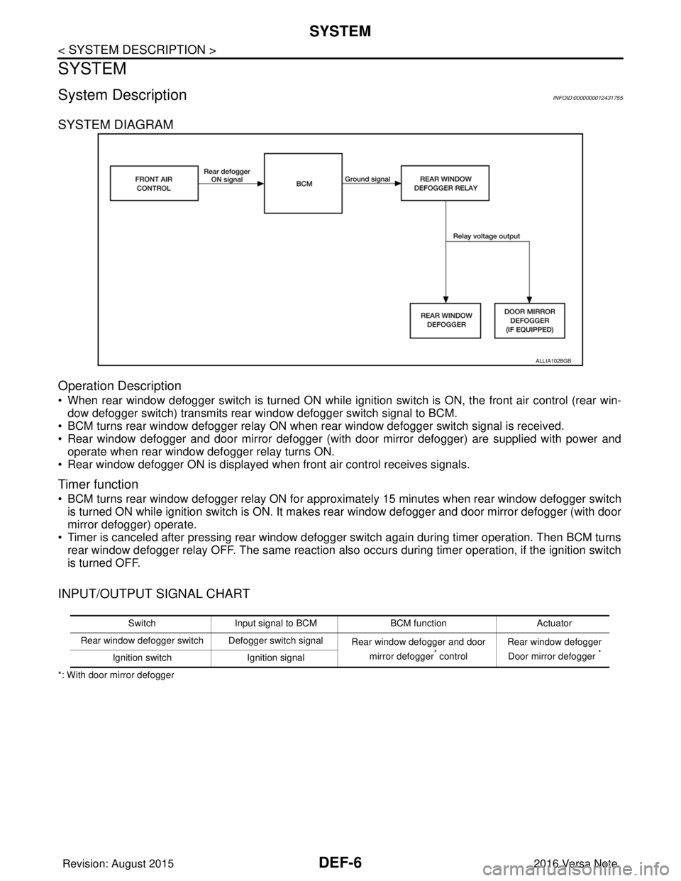
SYSTEM DIAGRAM
Operation Description
• When rear window defogger switch is turned ON while ignition switch is ON, the front air control (rear win-dow defogger switch) transmits rear window defogger switch signal to BCM.
• BCM turns rear window defogger relay ON when rear window defogger switch signal is received.
• Rear window defogger and door mirror defogger (with door mirror defogger) are supplied with power and operate when rear window defogger relay turns ON.
• Rear window defogger ON is displayed when front air control receives signals.
Timer function
• BCM turns rear window defogger relay ON for appr oximately 15 minutes when rear window defogger switch
is turned ON while ignition switch is ON. It makes rear window defogger and door mirror defogger (with door
mirror defogger) operate.
• Timer is canceled after pressing rear window defogger switch again during timer operation. Then BCM turns rear window defogger relay OFF. The same reaction also occurs during timer operation, if the ignition switch
is turned OFF.
INPUT/OUTPUT SIGNAL CHART
*: With door mirror defogger
ALLIA1028GB
Switch Input signal to BCM BCM functionActuator
Rear window defogger switch Defogger switch signal Rear window defogger and door
mirror defogger
* control Rear window defogger
Door mirror defogger *Ignition switch Ignition signal
Revision: August 2015 2016 Versa Note
cardiagn.com