Page 17 of 36
 , position the two vehicles (A and B) to bring their
12-volt batteries into close proximity to each other.
DO NOT all")
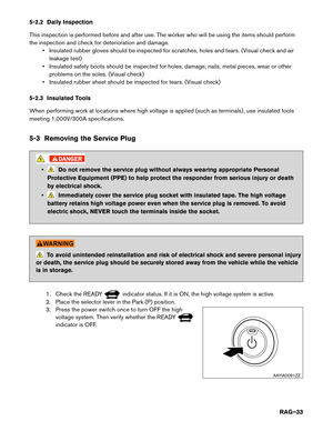
4-1.1 Jump Starting Procedures
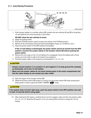
1. If the booster battery is in another vehicle (B) , position the two vehicles (A and B) to bring their
12-volt batteries into close proximity to each other.
DO NOT allow the two vehicles to touch.
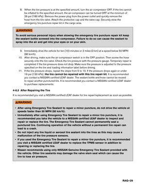
2. Apply the parking brake.
3. Push the P (Park) position switch to place the vehicle in the P (Park) position.
4. Switch off all unnecessary electrical systems (headlights, heater, air conditioner, etc.) .
5. Place the power switch in the OFF position (if possible) .
If the 12-volt battery is discharged, the power switch cannot be moved from the OFF
position. Connect the jumper cables to the booster vehicle (B) before pushing the
power switch.
6. Remove the vent caps on the 12-volt battery (if so equipped) . Cover the battery with a firmly wrung out moist cloth to reduce the hazard of an explosion.
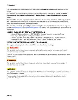
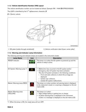
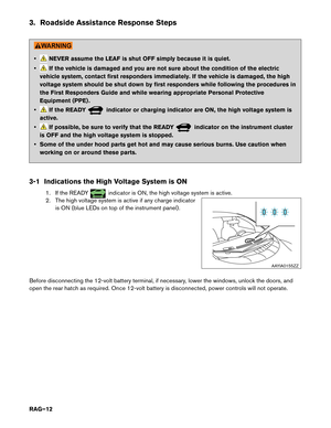
7. Connect jumper cables in the sequence as illustrated (�������) . • Always connect positive (+) to positive (+) and negative (-) to body ground (for example,
as
illustrated) , not to the 12-volt battery
• Make sure the jumper cables do not touch moving parts in the motor compartment and that the cable clamps do not contact any other metal.
8. Start the engine of the booster vehicle (B) .
9. While the booster vehicle (B) engine is running, turn the power switch ON while pressing the brake pedal in order to place the LEAF in READY mode.
If the system does not start right away, push the power switch to the OFF position and wait
at
least 10 seconds before trying again.
10. After starting the EV system, carefully disconnect the negative cable and then the positive cable (�������) . Keep the EV system on for over twenty (20) minutes to charge the 12-volt
battery. AAYIA0160ZZ
RAG–17
Page 18 of 36
 . Be sure to properly dispose of the cloth used to cover
the vent holes because it may be contaminated with corrosive acid.
12. If necessary, connect the veh")
11. Replace the vent caps (if so equipped) . Be sure to properly dispose of the cloth used to cover
the vent holes because it may be contaminated with corrosive acid.
12. If necessary, connect the vehicle to a charging station or EVSE (Electric Vehicle Supply Equipment) to charge the high voltage battery. The vehicle cannot be driven unless the high
voltage battery is charged.
NOTE:
If it is not possible to turn the LEAF system ON by following this procedure, it is
recommended you contact a NISSAN certified LEAF dealer immediately.
4-2 P (Park) Position Release Procedure
If you need to release the vehicle from the P (Park) position, proceed as follows. When power switch is
turned OFF or 12-volt battery is low, LEAF automatically shifts to P position.
NOTE: This procedure requires two (2) people.
1. To start the EV system with a booster battery, refer to 4-1 Jump Starting (RAG–16).
2.
Turn power switch ON by pushing the power switch 2 times without pressing brake pedal.
3. Confirm parking brake is applied.
4. Close all doors and press and hold the brake pedal.
5. Place the selector lever in the N (Neutral) position.
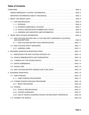
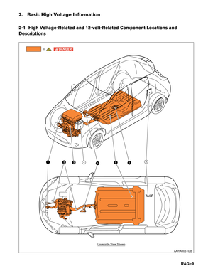
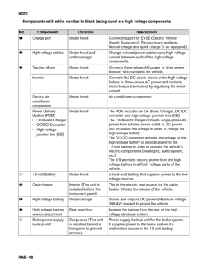
6. Remove the following 2 fuses:
• F/L 40A PBW MTR (under hood fuse and relay box)
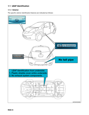
• METER 1 10A (in the cabin fuse box)
RAG–18
Page 19 of 36
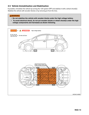
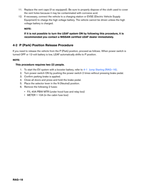
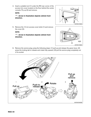
Under Hood Fuse and Relay Box Location
NO
TE: : Arrow in illustration depicts vehicle front direction. F/L 40A PBW MTR
AAYIA0163ZZ
RAG–19
Page 20 of 36
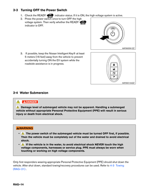
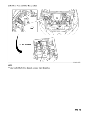
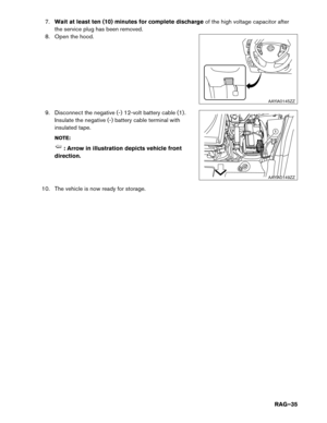
Cabin Fuse Box Location
NO
TE:
Insert a screwdriver wrapped with a protective cloth (A) into the slit (1) . Pull to remove the fuse
box cover (2) . Remove the fuse with the fuse puller (3) .
7. Release the parking brake.
8. Turn the power switch OFF.
9. Release brake pedal. To avoid possible personal injury or vehicle damage, use wheel chocks or take appropriate
steps
to prevent the vehicle from rolling freely.
Be sure to firmly position wheel chocks when P (Park) position is manually released.
4-2.1 Reset Procedure 1. Install the 2 fuses removed previously.
2. Turn the power switch ON and wait 5 seconds without pressing the brake pedal. Ensure selectorlever is in the N (neutral) position.
3. If 12-volt battery is low voltage, please charge with battery charger.
4. Turn the power switch OFF and wait 5 seconds. UP
METER 1
10A
11 3
2
A
AAYIA0151ZZ
RAG–20
Page 21 of 36

Width 69.7 in. (1,770 mm)
Overall Height 61.0 in. (1,550 mm)
Wheel Base 106.3 in. (2,700 mm)
Minimum ground clearance 6.3 in. (160 mm")
4-3 Towing
4-3.1
Vehicle Specifications Length
175
in. (4,445 mm)
Width 69.7 in. (1,770 mm)
Overall Height 61.0 in. (1,550 mm)
Wheel Base 106.3 in. (2,700 mm)
Minimum ground clearance 6.3 in. (160 mm)
Overall vehicle weight 3,256-3,346 lbs. (1,477-1,518 kg)
(Weight varies by equipment and trim level.)
Front approach angle 17°
Rear departure angle 26°
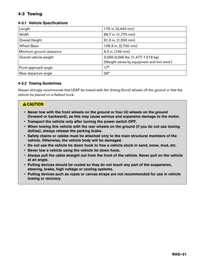
4-3.2 Towing Guidelines
Nissan strongly recommends that LEAF be towed with the driving (front) wheels off the ground or that the
vehicle be placed on a flatbed truck. • Never tow with the front wheels on the ground or four (4) wheels on the ground
(forward
or backward) , as this may cause serious and expensive damage to the motor.
• Transport the vehicle only after turning the power switch OFF.
• When towing this vehicle with the rear wheels on the ground (if you do not use towing dollies) , always release the parking brake.
• Safety chains or cables must be attached only to the main structural members of the vehicle. Otherwise, the vehicle body will be damaged.
• Do not use the vehicle tie down hook to free a vehicle stuck in sand, snow, mud, etc.
• Never tow a vehicle using the vehicle tie down hook.
• Always pull the cable straight out from the front of the vehicle. Never pull on the vehicle at an angle.
• Pulling devices should be routed so they do not touch any part of the suspension, steering, brake, high voltage or cooling systems.
• Pulling devices such as ropes or canvas straps are not recommended for use in vehicle towing or recovery.
RAG–21
Page 22 of 36
 wheels or on flatbed in order to prevent secondary
damage
from voltage generated by the motor. In addition, turn the power switch OFF when towing the")
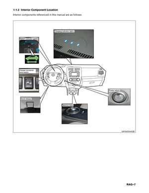
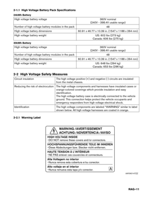
Perform vehicle towing by holding up drive (front) wheels or on flatbed in order to prevent secondary
damage
from voltage generated by the motor. In addition, turn the power switch OFF when towing the
vehicle. Refer to the following illustration:
NOTE:
It is also permissible to transport the LEAF facing rearward on a flatbed.
NOTE:
If the vehicle cannot be placed in Neutral, a P (Park) release procedure may be required.
Refer to 4-2 P (Park) Position Release Procedure (RAG–18).
4-3.3
Use of Vehicle Equipped Hooks for Recovery Operations It is important to correctly attach the recovery strap, chain, or other device to the vehicle.
The
vehicle tie down points are not designed for recovery use. Only attach the strap, chain,
or other device to a suitably rated vehicle recovery point. Failure to do so may result in
the strap, chain, or other device, or a vehicle component, detaching from the vehicle and
striking a person causing serious injury or death or vehicle damage. AAYIA0176ZZ
RAG–22
Page 23 of 36
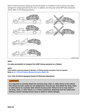
Front Tie Down Hook:
• Do not use the front tie down hook for towing or vehicle
recovery.
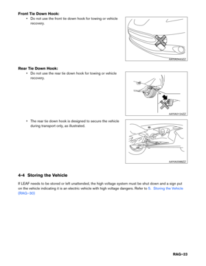
Rear Tie Down Hook: • Do not use the rear tie down hook for towing or vehiclerecovery.
• The rear tie down hook is designed to secure the vehicle during transport only, as illustrated.
4-4 Storing the Vehicle
If LEAF needs to be stored or left unattended, the high voltage system must be shut down and a sign put
on the vehicle indicating it is an electric vehicle with high voltage dangers. Refer to 5. Storing the Vehicle
(RAG–30) AAYIA0463ZZ
AAYIA0124ZZ
AAYIA0088ZZ
RAG–23
Page 24 of 36

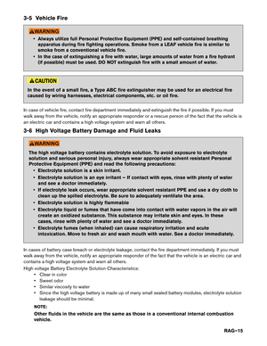
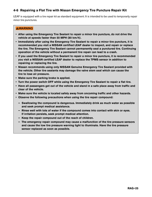
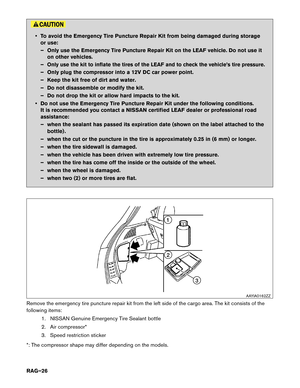
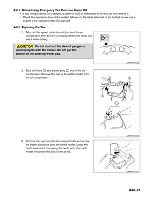
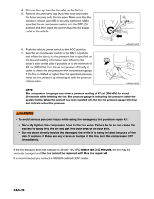
4-5 Jacking Up the Vehicle and Changing a Tire
LEAF
is not equipped with a jack or spare tire as standard equipment. However, the following jacking
instructions apply when using the optional Nissan jack.
1. Place the jack directly under the jack-up point asillustrated so the top of the jack contacts the vehicle
at the jack-up point. Align the jack head between the two
notches in the front or the rear as shown. Also fit the
groove of the jack head between the notches as shown.
The jack should be used on level firm ground.
2. Loosen each wheel nut one or two turns by turning it counterclockwise with the wheel nut wrench. Do not remove the wheel nuts until the tire is off the ground.
3. To lift the vehicle, securely hold the jack lever and rod with both hands as shown. Carefully raise the vehicle until the tire clears the ground. Remove the wheel nuts, and then remove the tire.
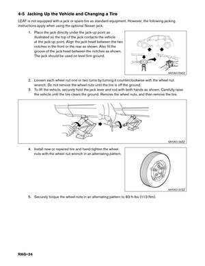
4. Install new or repaired tire and hand-tighten the wheel nuts with the wheel nut wrench in an alternating pattern.
5. Securely torque the wheel nuts in an alternating pattern to 83 ft-lbs (113 Nm) . AAYIA0109ZZ
AAYIA0136ZZ
B
EC DA
AAYIA0137ZZ
RAG–24


 into the slit (1) . Pull to remove the fuse
box cover (2) . Remove the fuse with the fuse puller (3) .
7. Releas")
