2016 MITSUBISHI OUTLANDER ESP
[x] Cancel search: ESPPage 416 of 464

Tires 9-18 Vehicle care and maintenance
9
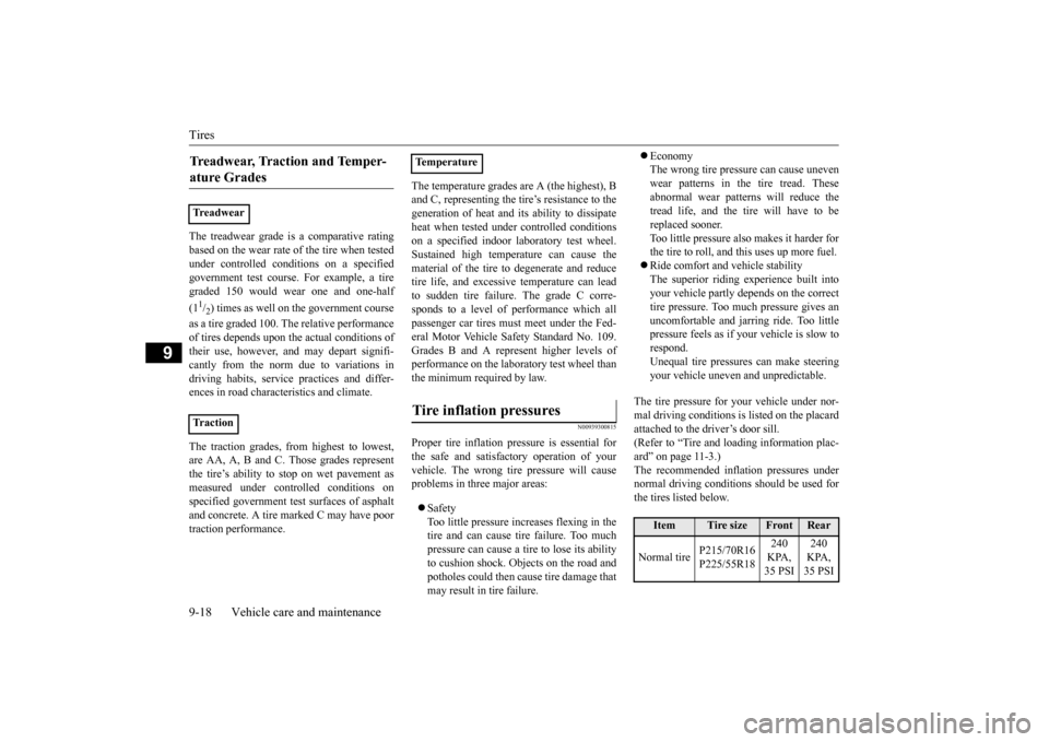
The treadwear grade is a comparative rating based on the wear rate of
the tire when tested
under controlled conditions on a specified government test course
. For example, a tire
graded 150 would wear one and one-half (11/2) times as well on the government course
as a tire graded 100.
The relative performance
of tires depends upon the actual conditions of their use, however, and may depart signifi-cantly from the norm due to variations in driving habits, service
practices and differ-
ences in road characteristics and climate. The traction grades, from highest to lowest, are AA, A, B and C. Those grades represent the tire’s ability to stop on wet pavement as measured under contro
lled conditions on
specified government te
st surfaces of asphalt
and concrete. A tire
marked C may have poor
traction performance.
The temperature grades are A (the highest), B and C, representing the ti
re’s resistance to the
generation of heat and it
s ability to dissipate
heat when tested un
der controlled conditions
on a specified indoor
laboratory test wheel.
Sustained high temperature can cause the material of the tire to
degenerate and reduce
tire life, and excessive temperature can leadto sudden tire failure. The grade C corre- sponds to a level of performance which all passenger car tires must
meet under the Fed-
eral Motor Vehicle Safety Standard No. 109. Grades B and A represent higher levels ofperformance on the laboratory test wheel than the minimum required by law.
N00939300815
Proper tire inflation pre
ssure is essential for
the safe and satisfac
tory operation of your
vehicle. The wrong tire pressure will causeproblems in three major areas: Safety Too little pressure increases flexing in the tire and can cause tire failure. Too muchpressure can cause a tire to lose its ability to cushion shock. Objects on the road and potholes could then ca
use tire damage that
may result in tire failure.
Economy The wrong tire pressure can cause unevenwear patterns in the tire tread. These abnormal wear patterns will reduce the tread life, and the tire will have to bereplaced sooner. Too little pressure also makes it harder for the tire to roll, and this uses up more fuel. Ride comfort and vehicle stability The superior riding ex
perience built into
your vehicle partly depends on the correct tire pressure. Too mu
ch pressure gives an
uncomfortable and ja
rring ride. Too little
pressure feels as if your vehicle is slow to respond. Unequal tire pressures can make steeringyour vehicle uneven
and unpredictable.
The tire pressure for your vehicle under nor- mal driving conditions is
listed on the placard
attached to the driver’s door sill.(Refer to “Tire and loading information plac- ard” on page 11-3.) The recommended inflation pressures undernormal driving conditions should be used for the tires listed below.
Treadwear, Traction and Temper- ature Grades Treadwear Tr a c t i o n
TemperatureTire inflation pressures
Item
Tire size
Front
Rear
Normal tire
P215/70R16 P225/55R18
240 KPA, 35 PSI
240 KPA, 35 PSI
BK0223400US.book 18 ページ 2015年2月13日 金曜日 午後12時15分
Page 421 of 464

General maintenance
Vehicle care and maintenance 9-23
9
N00940900231
Spark plugs must fire properly to ensure proper engine performance and emission- control.Do not reuse spark plugs by cleaning or regapping. Spark plugs
should be replaced at
the mileage specified in the “WARRANTYAND MAINTENANCE MANUAL”.
N00941000040
Check the hose surfaces for any heat and mechanical damage, ha
rd and brittle rubber,
cracking, tears, cuts and abrasions. Pay spe-cial attention to the hos
es closest to high heat
sources such as the exhaust manifold. Check all the hose connections, such as clamps andcouplings, to make sure they are secure and that there are no leaks. If you see any wear or damage, replace the
hoses immediately.
N00950100050
Have the valve clea
rance checked at an
authorized Mitsubishi Motors dealer at the mileage specified in the “WARRANTY AND MAINTENANCE MANUAL”.If the engine sounds ab
normally loud, have
adjustments made by an authorized Mitsubishi Motors dealer.
N00941300173
Check these regularly for damage or leaks in the fuel lines and conne
ctions. Check the fuel
tank filler cap for dama
ge or looseness. Pay
special attention to the fuel lines closest to
high heat sources such
as the exhaust mani-
fold.
N00941400187
If the fuel-vapor vent line is clogged or dam-aged, the fuel-vapor mixture will escape, pol- luting the air. Have the system checked at an authorizedMitsubishi Motors dealer at the mileage spec- ified in the “WARRANTY AND MAINTE- NANCE MANUAL”.
N00941501299
The next pages list th
e maintenance service
recommended by Mitsubishi Motors Corpo-ration. In addition to the general maintenance that needs to be performed at the times listed,
NOTE
To meet government
regulations and pro-
mote cleaner air, your
vehicle is equipped
with an onboard diagnostic system (OBD).The engine electroni
c control module that
controls OBD functions
stores various data
(especially about th
e exhaust emissions).
This data will be erased if the battery cable is disconnected, which c
ould make a rapid
diagnosis difficult. Do not disconnect thebattery cable when th
e engine malfunction
indicator (“SERVIC
E ENGINE SOON” or
“Check engine light”) is ON.
Spark plugs
NOTE
Use the recommended or
equivalent spark
plugs listed under “Engi
ne specifications” on
page 11-6. Use of other plugs could cause engine damage, loss of
performance or radio
noise.
Fuel hoses Intake valve clearance Fuel system (tank, pipe line and connection, and fuel tank filler cap)
WA R N I N G If you see a fuel leak
or if you smell fuel,
do not run the engine. Any spark (includ- ing from the ignition
), flame or smoking
material could cause an explosion or fire.Call an authorized Mitsubishi Motors dealer or a repair fa
cility of your choice
for assistance.
Evaporative emission control system (except evaporative emission canister) General maintenance
BK0223400US.book 23 ページ 2015年2月13日 金曜日 午後12時15分
Page 425 of 464

Fuses
Vehicle care and maintenance 9-27
9
*: Fusible link Some fuses may not be installed on your vehicle, depending on
the vehicle model
or specifications. The table above show
s the main equip-
ment corresponding to each fuse. 20 Back-up lights 7.5 A 21
Heated outside rearview mirrors
7.5 A
22
Outside rearview
mirrors
10 A
23
Cigarette lighter/ 12 V power outlet
15 A
24 Charge 7.5 A 25 Power seat 30 A*26 Heated seats 30 ANo.
Sym- bol
Electrical system
Capacity
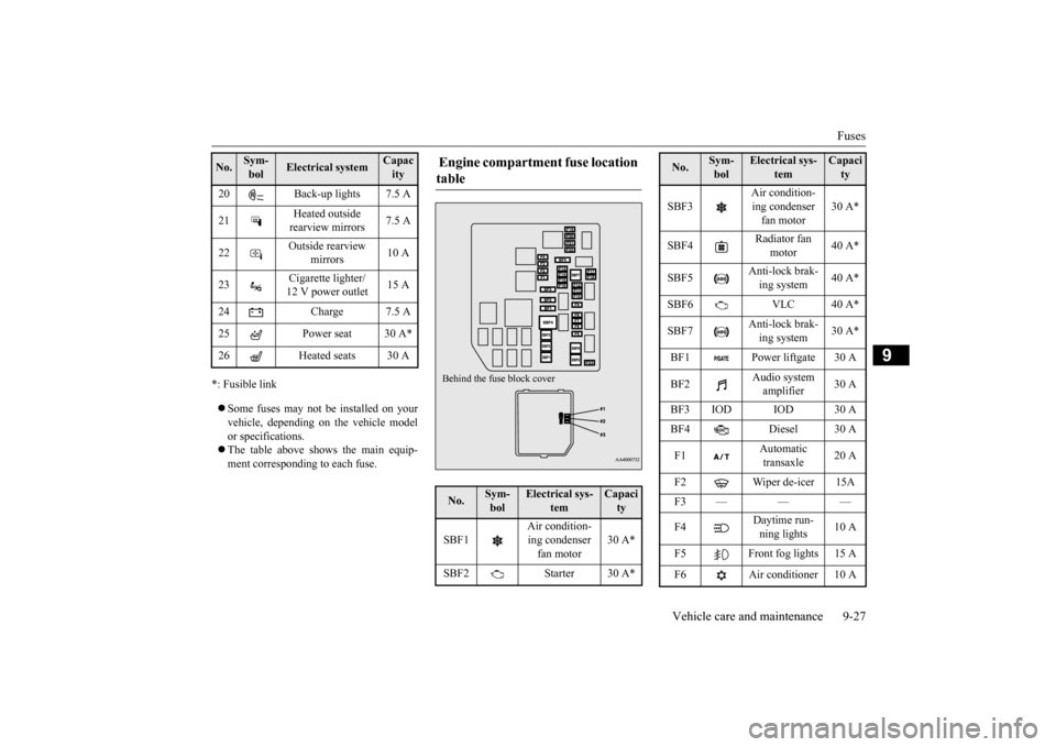
Engine compartment fuse location table No.
Sym- bol
Electrical sys-
tem
Capacity
SBF1
Air condition- ing condenser fan motor
30 A*
SBF2 Starter 30 A*Behind the fuse block cover
SBF3
Air condition- ing condenser fan motor
30 A*
SBF4
Radiator fan
motor
40 A*
SBF5
Anti-lock brak- ing system
40 A*
SBF6 VLC 40 A* SBF7
Anti-lock brak- ing system
30 A*
BF1 Power liftgate 30 A BF2
Audio system amplifier
30 A
BF3 IOD IOD 30 A BF4 Diesel 30 A F1
Automatic transaxle
20 A
F2 Wiper de-icer 15A F3——— F4
Daytime run- ning lights
10 A
F5 Front fog lights 15 A F6 Air conditioner 10 ANo.
Sym- bol
Electrical sys-
tem
Capacity
BK0223400US.book 27 ページ 2015年2月13日 金曜日 午後12時15分
Page 426 of 464

Fuses 9-28 Vehicle care and maintenance
9
*: Fusible link Some fuses may not be installed on your vehicle, depending on
the vehicle model
or specifications. The table above show
s the main equip-
ment corresponding to each fuse.
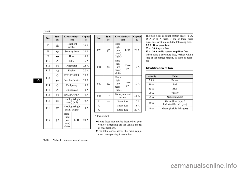
The fuse block does not contain spare 7.5 A, 25 A or 30 A fuses. If one of these fusesburns out, substitute wi
th the following fuse.
7.5 A: 10 A spare fuse 25 A: 20 A spare fuse30 A: 30 A audio system amplifier fuse When using a substitute fuse, replace with a fuse of the correct capacity as soon as possi-ble.
F7
Headlight washer
20 A
F8 Security horn 20 A F9 Horn 10 AF10 ETV 15 A F11 Alternator 7.5 A F12 Engine 7.5 A F13
ENG/POWER 20 A Fuel line heater 25 A
F14 Fuel pump 15 A F15 Ignition coil 10 A F16 ENG/POWER 10 A F17
Headlight (high beam) (left)
10 A
F18
Headlight (high beam) (right)
10 A
F19
Head- light (low beam) (left)
LED 20 A
No.
Sym- bol
Electrical sys-
tem
Capacity
F20
Head- light (low beam) (right)
LED 20 A
F21
Head- light (low beam) (left)
Halo- gen
10 A
F22
Head- light (low beam) (right)
Halo- gen
10 A
F23
Battery current
sensor
7.5 A
#1 — Spare fuse 10 A #2 — Spare fuse 15 A #3 — Spare fuse 20 ANo.
Sym- bol
Electrical sys-
tem
Capacity
Identification of fuse Capacity
Color
7.5 A Brown 10 A Red 15 A Blue 20 A Yellow 25 A Natural (white) 30 A
Green (fuse type) / Pink (fusible link type)
40 A Green (fusible link type)
BK0223400US.book 28 ページ 2015年2月13日 金曜日 午後12時15分