2016 MITSUBISHI OUTLANDER battery
[x] Cancel search: batteryPage 267 of 464
Horn switch
Features and controls 5-191
5
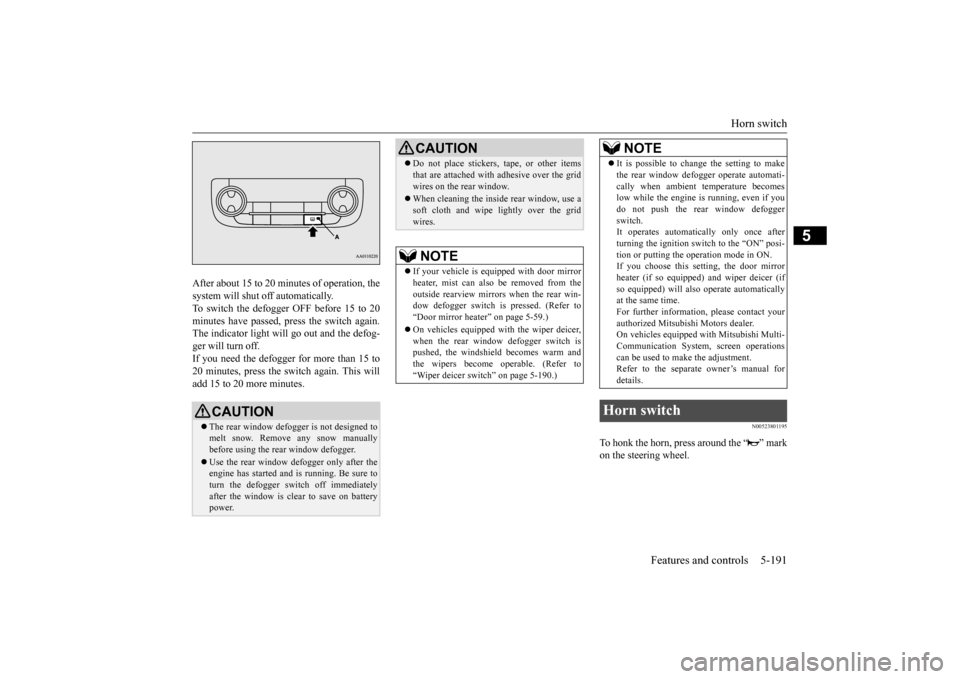
After about 15 to 20 minutes of operation, the system will shut off automatically.To switch the defogger OFF before 15 to 20 minutes have passed, pr
ess the switch again.
The indicator light will go out and the defog-ger will turn off. If you need the defogger for more than 15 to 20 minutes, press the switch again. This willadd 15 to 20 more minutes.
N00523801195
To honk the horn, press around the “ ” markon the steering wheel.
CAUTION The rear window defogge
r is not designed to
melt snow. Remove
any snow manually
before using the rear window defogger. Use the rear window de
fogger only after the
engine has started and
is running. Be sure to
turn the defogger swit
ch off immediately
after the window is cl
ear to save on battery
power.
Do not place stickers
, tape, or other items
that are attached with
adhesive over the grid
wires on the rear window. When cleaning the insi
de rear window, use a
soft cloth and wipe lightly over the gridwires.NOTE
If your vehicle is equi
pped with door mirror
heater, mist can also be removed from the outside rearview mirrors
when the rear win-
dow defogger switch is pressed. (Refer to“Door mirror heater” on page 5-59.) On vehicles equipped wi
th the wiper deicer,
when the rear window defogger switch is pushed, the windshield becomes warm and the wipers become operable. (Refer to“Wiper deicer switch” on page 5-190.)CAUTION
It is possible to change the setting to make the rear window defogger operate automati-cally when ambient temperature becomeslow while the engine is running, even if you do not push the rear window defogger switch.It operates automati
cally only once after
turning the ignition sw
itch to the “ON” posi-
tion or putting the ope
ration mode in ON.
If you choose this setting, the door mirror heater (if so equipped)
and wiper deicer (if
so equipped) will also
operate automatically
at the same time. For further informati
on, please contact your
authorized Mitsubish
i Motors dealer.
On vehicles equipped
with Mitsubishi Multi-
Communication System
, screen operations
can be used to make the adjustment.Refer to the separate owner’s manual for details.
Horn switch
NOTE
BK0223400US.book 191 ページ 2015年2月13日 金曜日 午後12時15分
Page 269 of 464
Bluetooth® 2.0 interface (if so equipped)
Features and controls 5-193
5
Steering control swit
ch and microphone
P.5-193Voice recognition function
P.5-195
Useful voice commands
P.5-196
Speaker enrollment function
P.5-197
Connecting the Bluetooth
® 2.0 interface and
the Bluetooth
® device
P.5-199
Operating a music player connected via Blue- tooth
® P.5-205
How to make or receive hands-free calls
P.5-205Phonebook function
P.5-207
N00564001109
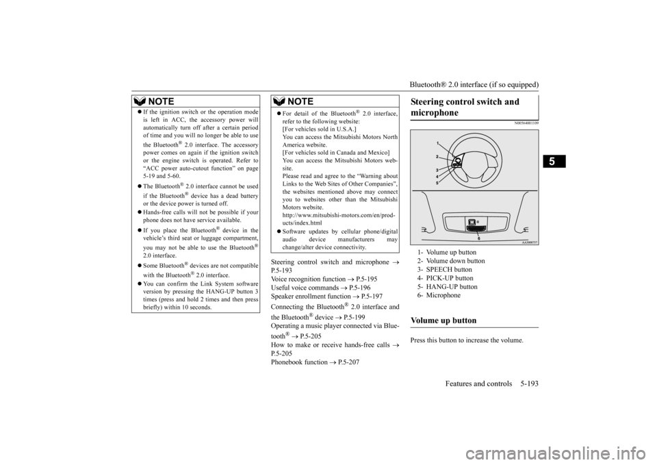
Press this button to increase the volume.
NOTE
If the ignition switch
or the operation mode
is left in ACC, the accessory power willautomatically turn off after a certain periodof time and you will no longer be able to use the Bluetooth
® 2.0 interface. The accessory
power comes on again if the ignition switch or the engine switch is operated. Refer to“ACC power auto-cutout
function” on page
5-19 and 5-60. The Bluetooth
® 2.0 interface
cannot be used
if the Bluetooth
® device has a dead battery
or the device power is turned off. Hands-free calls will
not be possible if your
phone does not have
service available.
If you place the Bluetooth
® device in the
vehicle’s third seat or luggage compartment, you may not be able to use the Bluetooth
®
2.0 interface. Some Bluetooth
® devices are not compatible
with the Bluetooth
® 2.0 interface.
You can confirm the Link System software version by pressing the HANG-UP button 3times (press and hold 2 times and then press briefly) within 10 seconds.
For detail of the Bluetooth
® 2.0 interface,
refer to the following website: [For vehicles sold in U.S.A.] You can access the Mits
ubishi Motors North
America website. [For vehicles sold in
Canada and Mexico]
You can access the Mitsubishi Motors web-site. Please read and agree to the “Warning about Links to the Web Sites of Other Companies”,the websites mentione
d above may connect
you to websites other than the Mitsubishi Motors website.http://www.mitsubishi
-motors.com/en/prod-
ucts/index.html Software updates by cellular phone/digital audio device manufacturers may change/alter devi
ce connectivity.
NOTE
Steering control switch and microphone
1- Volume up button 2- Volume down button 3- SPEECH button4- PICK-UP button 5- HANG-UP button 6- MicrophoneVolume up button
BK0223400US.book 193 ページ 2015年2月13日 金曜日 午後12時15分
Page 294 of 464
Sun visors 5-218 Features and controls
5
N00567201056
You can play music files of the following specifications that are saved in a USB mem- ory device or other device supporting mass storage class. When you connect your iPod,playable file specifications depend on the connected iPod.
N00524601363
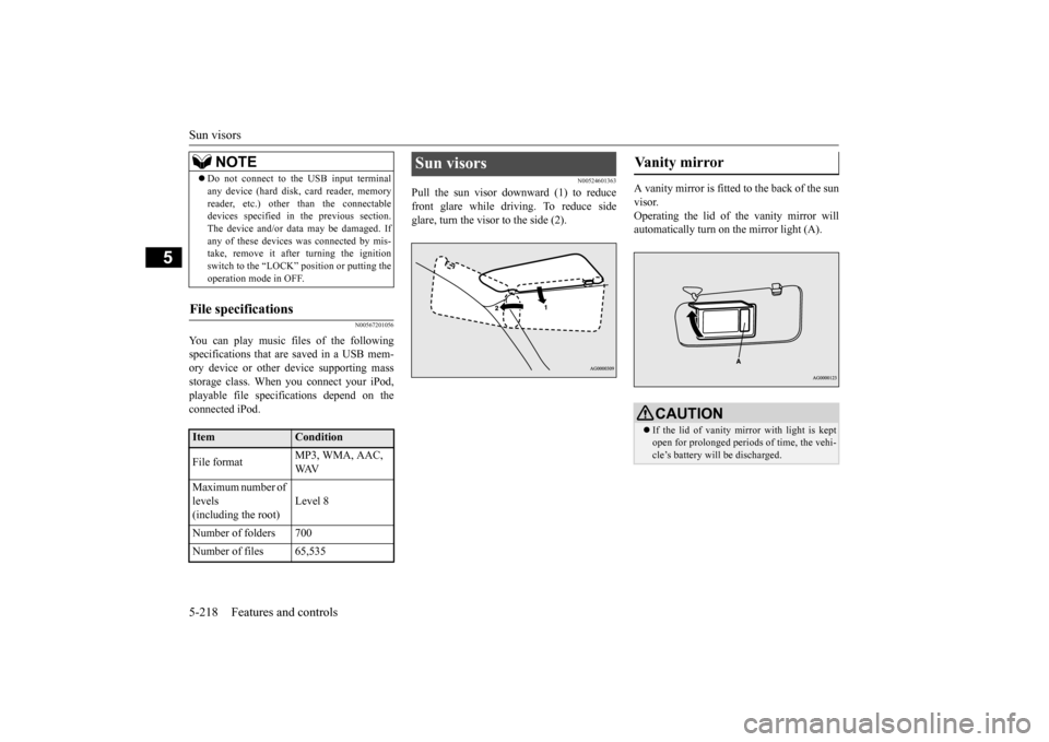
Pull the sun visor downward (1) to reducefront glare while driving. To reduce side glare, turn the visor to the side (2).
A vanity mirror is fitted to the back of the sun visor. Operating the lid of the vanity mirror will automatically turn on the mirror light (A).
Do not connect to the USB input terminal any device (hard disk, card reader, memoryreader, etc.) other than the connectabledevices specified in the previous section. The device and/or data
may be damaged. If
any of these devices
was connected by mis-
take, remove it afte
r turning the ignition
switch to the “LOCK”
position or putting the
operation mode in OFF.
File specifications
Item
Condition
File format
MP3, WMA, AAC, WAV
Maximum number of levels (including the root)
Level 8
Number of folders 700 Number of files 65,535
NOTE
Sun visors
Vanity mirror
CAUTION If the lid of vanity mirror with light is kept open for prolonged periods
of time, the vehi-
cle’s battery will be discharged.
BK0223400US.book 218 ページ 2015年2月13日 金曜日 午後12時15分
Page 295 of 464
12 V power outlets
Features and controls 5-219
5
Cards can be slipped into the holder (B) on the sun visor.
N00525001625
To use a “plug-in” type accessory, open thecover or remove the cap, and insert the plugin the power outlet.
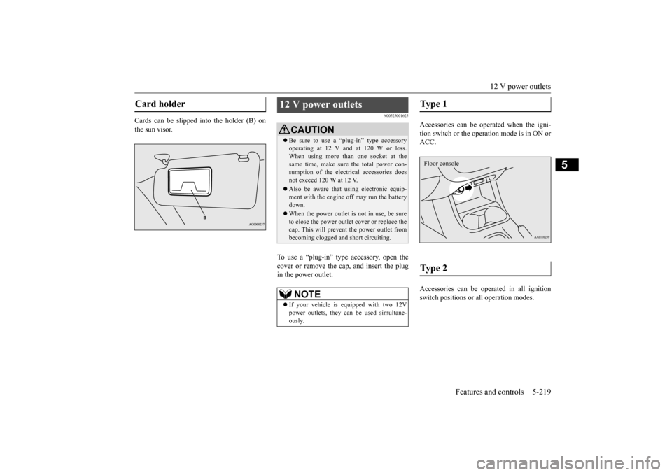
Accessories can be operated when the igni- tion switch or the operation mode is in ON or ACC. Accessories can be ope
rated in all ignition
switch positions or
all operation modes.
Card holder
12 V power outlets
CAUTIONBe sure to use a “plug-in” type accessory operating at 12 V and at 120 W or less.When using more than one socket at the same time, make sure
the total power con-
sumption of the electrical accessories doesnot exceed 120 W at 12 V. Also be aware that
using electronic equip-
ment with the engine
off may run the battery
down. When the power outlet is not in use, be sure to close the power outle
t cover or replace the
cap. This will prevent the power outlet frombecoming clogged and short circuiting.NOTE
If your vehicle is e
quipped with two 12V
power outlets, they ca
n be used simultane-
ously.
Type 1 Type 2 Floor console
BK0223400US.book 219 ページ 2015年2月13日 金曜日 午後12時15分
Page 297 of 464
HomeLink® Wireless Control System (if so equipped)
Features and controls 5-221
5
N00584600029
Some garage door openers manufactured after 1995 have “rolli
ng code protection”.
To program a garage door opener equipped with “rolli
ng code protection”;
you will need to access the garage dooropener motor to press the motor’s “Learn” or “Smart” buttons. For convenience, use a ladder and another person to assist you. It is recommended that a new battery be placed in the hand-held transmitter of the device being programmed to HomeLink
®
for quicker training and accurate trans- mission of the radio-frequency signal.
N00584700020
To program HomeLink
® to operate a garage
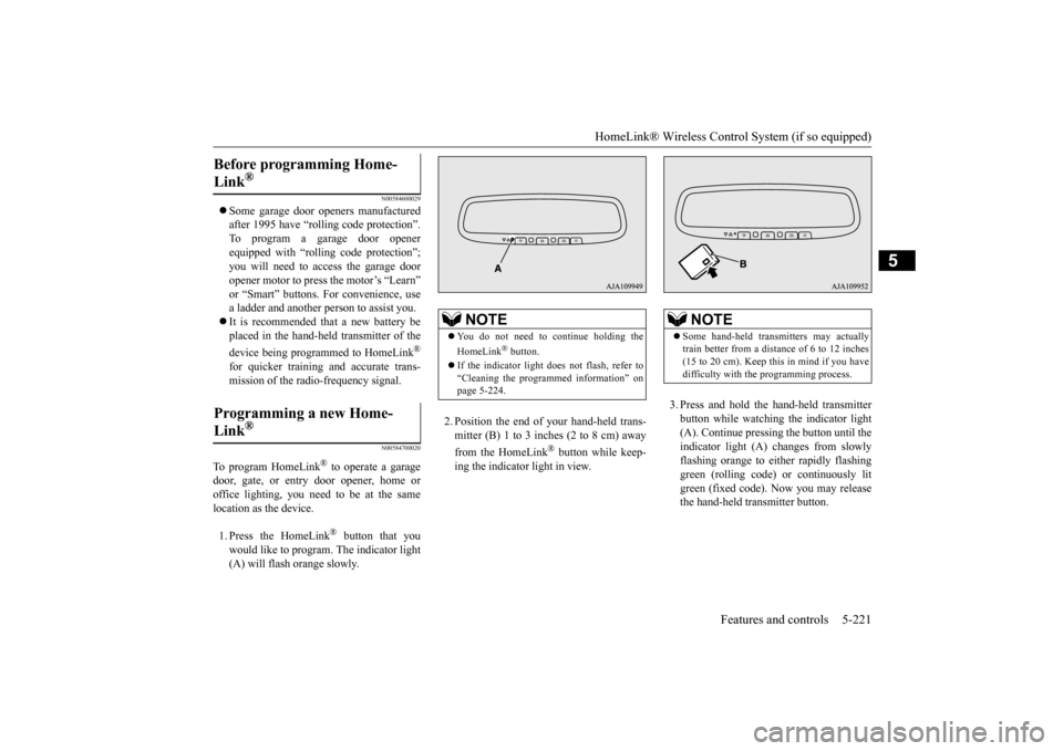
door, gate, or entry door opener, home or office lighting, you need to be at the same location as the device. 1. Press the HomeLink
® button that you
would like to program. The indicator light (A) will flash orange slowly.
2. Position the end of your hand-held trans- mitter (B) 1 to 3 inches (2 to 8 cm) away from the HomeLink
® button while keep-
ing the indicator light in view.
3. Press and hold the hand-held transmitter button while watching
the indicator light
(A). Continue pressing the button until the indicator light (A)
changes from slowly
flashing orange to either rapidly flashinggreen (rolling code) or continuously lit green (fixed code). Now you may release the hand-held transmitter button.
Before programming Home- Link
®
Programming a new Home-Link
®
NOTE
You do not need to continue holding the HomeLink
® button.
If the indicator light doe
s not flash, refer to
“Cleaning the programmed information” on page 5-224.
NOTE
Some hand-held transmitters may actually train better from a distance of 6 to 12 inches(15 to 20 cm). Keep this in mind if you have difficulty with th
e programming process.
BK0223400US.book 221 ページ 2015年2月13日 金曜日 午後12時15分
Page 301 of 464
Interior lights
Features and controls 5-225
5
N00585600026
Your HomeLink
® system operates on a radio
frequency subject to
Federal Communica-
tions Commission (FCC)
Rules (For vehicles
sold in U.S.A.) and Industry Canada Rules (For vehicles sold in Canada). This devicecomplies with Part 15 of the FCC Rules and RSS- 210 of the Industry Canada Rules. Operation is subject to the following two con-ditions. This device may not
cause harmful inter-
ference. This device must ac
cept any interference
that may be received, including interfer- ence that may cause undesired operation.
This equipment complies with FCC radiation exposure limits set forth for an uncontrolled environment. End Users must follow the spe- cific operating instructio
ns for satisfying RF
exposure compliance. This transmitter must be at least 12 inches (20 cm) from the user and must not be co-located or operating inconjunction with any other antenna or trans- mitter. The term “IC:” before
the certification/regis-
tration number only signi
fies that Industry
Canada technical spec
ifications were met.
N00525301602
NOTE
If you do not complete the programming of a new device to the button,
it will revert to the
previously stored programming.For questions or
comments, visit
www.homelink.com, www.youtube.com/HomeLinkGentex, or by calling the HomeLink
® Hotline.
General information
CAUTION The transmitter has been tested and complies with FCC and IC rules.Changes or modifica
tions not expressly
approved by the party responsible for com- pliance could void the user’s authority to operate the device.
Interior lights
NOTE
Be aware that leaving the light illuminated with the engine off may run the batterydown. Never leave the vehi
cle without checking
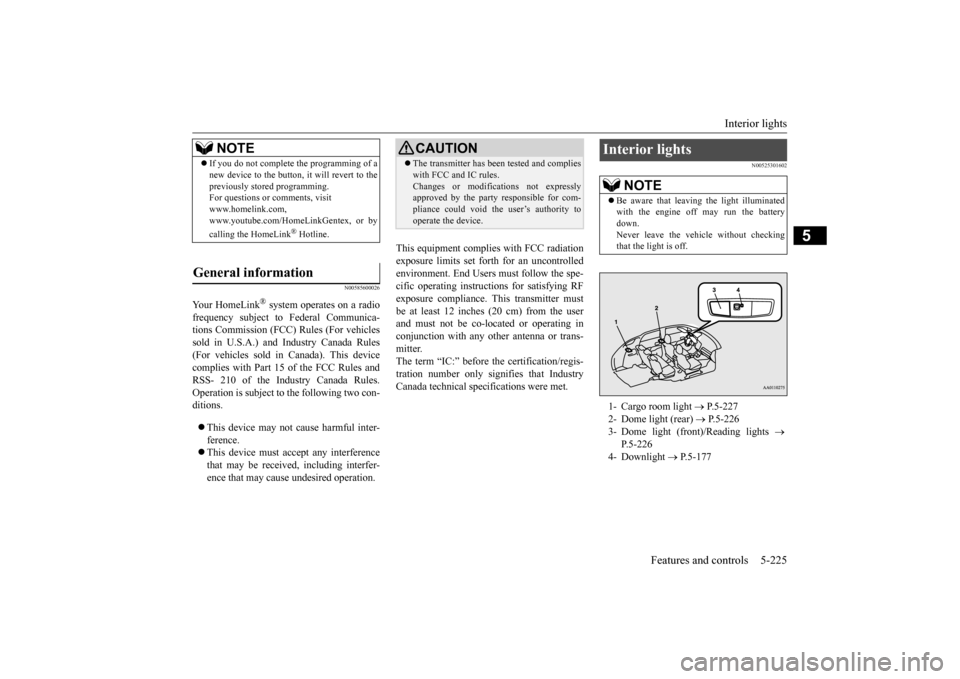
that the light is off.1- Cargo room light
P.5-227
2- Dome light (rear)
P.5-226
3- Dome light (front)/Reading lights
P.5-226
4- Downlight
P.5-177
BK0223400US.book 225 ページ 2015年2月13日 金曜日 午後12時15分
Page 317 of 464
Driving during cold weather
Driving safety 6-5
6
Always obey applicab
le laws and regula-
tions. Be a polite and alert driver. Alwaysleave room for unexpected events, such as sudden braking. If you plan to drive in another country, obey their vehicle re
gistration laws and
make sure you will be able to get the right fuel.
N00629400445
Check the battery. At the same time, check the terminals and wiring. During extremely cold weather, the battery will not be as strong. Also, the battery powerlevel may drop beca
use more power is
used for cold starting and driving. Before driving the vehicle, check to see ifthe engine runs at the proper speed and if the headlights are as
bright as normally.
Charge or replace the battery if necessary.During extreme cold weather, it is possi- ble that a very low battery could freeze.
Warm the engine sufficiently. After start- ing the engine, allow a short warm-uptime to distribute oil to all cylinders. Then drive your vehicle slowly. Stay at low speeds at first so that thetransaxle, transfer case and rear axle oil have time to spread to all lubrication points. Check the engine antifreeze. If there is not enough coolant because of a leak or from engine
overheating, add Mit-
subishi Motors Genuine Super Long Life Coolant Premium or equivalent.Please read this section in conjunction with the “Engine coolant” on page 9-8.
N00629501528
All the parts of the brake system are critical to safety. Have the vehicle serviced by anauthorized Mitsubishi Motors dealer or a repair facility of your
choice at regular inter-
vals according to the “WARRANTY ANDMAINTENANCE MANUAL”.
Check the brake system while driving at a low speed immediately
after starting, espe-
cially when the brakes are wet, to confirmthey work normally. A film of water can be formed on the brake discs and prevent normal braking after driv-ing in heavy rain or through large puddles, or after the vehicle is washed. If this occurs, dry the brakes out by drivi
ng slowly while lightly
depressing the brake pedal. On snowy roads, ice can form on the braking system, making the brakes less effective. While driving in such
conditions, pay close
attention to surrounding vehicles and to the condition of the road surface. From time to time, lightly depress the brake pedal andcheck how effective the brakes are. It is important to take advantage of the engine braking by downshifting while driving on steep downhill roads in order to prevent the brakes from overheating.
Driving during cold weather
WA R N I N G The battery gives o
ff explosive hydrogen
gas. Any spark or flame can cause the bat- tery to explode, which could cause serious injury or death.Always wear protecti
ve clothes and a face
mask when working with your battery, or let a skilled mechanic do it.
WA R N I N G Never open the radiator cap when the radiator is hot. You could be seriously burned.
Braking
When brakes are wet When driving in cold weather When driving downhill
BK0223400US.book 5 ページ 2015年2月13日 金曜日 午後12時15分
Page 319 of 464
Loading information Driving safety 6-7
6
Vehicle maximum load on the tire: load on an individual tire that is determined bydistributing to each axle its share of the maximum loaded vehicle weight and dividing by two. Vehicle normal load on the tire: load on an individual tire that is determined by dis- tributing to each axle its share of the curbweight, accessory weight, and normal occupant weight and dividing by two. Maximum loaded vehicle weight: the sum of - (a) Curb weight;(b) Accessory weight; (c) Vehicle capacity weight; and (d) Production options weight. Curb weight: the weight of a motor vehi- cle with standard e
quipment including the
maximum capacity of fuel, oil, and cool-ant. Accessory weight: the combined weight (in excess of those
standard items which
may be replaced) of automatic transmis- sion, power steering, power brakes, power windows, power seats, radio, and heater,to the extent that these items are available as factory- installed equipment (whether installed or not). Vehicle capacity weight: the rated cargo and luggage load plus 150 lbs (68 kg) * times the vehicle’s
designated seating
capacity.
Production options weight: the combined weight of those installed regular produc-tion options weighing over 5 lbs (2.3 kg) in excess of those standard items which they replace, not prev
iously considered in
curb weight or accessory weight, includ- ing heavy duty brakes,
ride levelers, roof
rack, heavy duty battery, and special trim. Normal occupant weight: 150 lbs (68 kg) * times the number of
specified occupants
(3 in the case of your vehicle) Occupant distribution:
Occupant distribu-
tion within the passenger compartment (Inyour vehicle the distribution is 2 in front, 1 in second row seat)
N00630101407
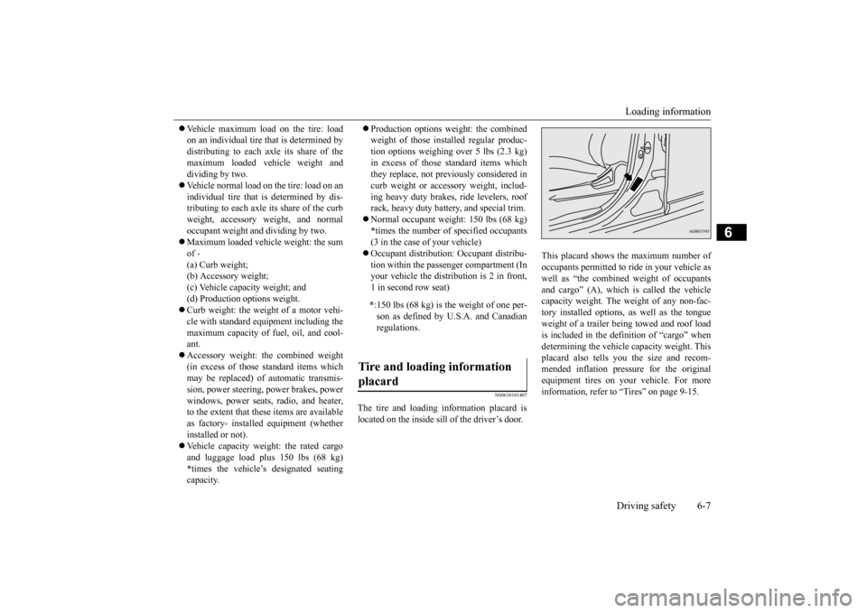
The tire and loading information placard is located on the inside sill of the driver’s door.
This placard shows the maximum number of occupants permitted to
ride in your vehicle as
well as “the combined
weight of occupants
and cargo” (A), which
is called the vehicle
capacity weight. The weight of any non-fac-tory installed options, as well as the tongue weight of a trailer being towed and roof load is included in the defi
nition of “cargo” when
determining the vehicle
capacity weight. This
placard also tells you the size and recom- mended inflation pressure for the originalequipment tires on your vehicle. For more information, refer to
“Tires” on page 9-15.
* :150 lbs (68 kg) is th
e weight of one per-
son as defined by U.S.A. and Canadian regulations.
Tire and loading information placard
BK0223400US.book 7 ページ 2015年2月13日 金曜日 午後12時15分