2016 MITSUBISHI OUTLANDER height
[x] Cancel search: heightPage 52 of 464
Child restraint systems 4-26 Seat and restraint systems
4
N00408701147
This warning light tells you if there is a prob- lem involving the SRS airbags and/or the seat belt pre-tensioner sy
stem. Refer to “SRS
warning light/display” on page 4-39.
N00408900126
In the event of an accident, the seat belt force limiter system will help reduce the force applied to the driver and front seat passenger.
N00407101740
When transporting infants or small childrenin your vehicle, an appropriate child restraintsystem must always be
used. This is required
by law in the U.S. and Canada. Child restraint systems specifically designedfor infants and small children are offered by several manufacturers
. Choose only a child
restraint system with a label certifying that itcomplies with Federal Motor Vehicle Safety Standard 213 (FMVSS 213) or Motor Vehicle Restraint Systems and Booster Seats SafetyRegulations (RSSR). Look for the manufac- turer’s statement of compliance on the box and child restraint system itself.
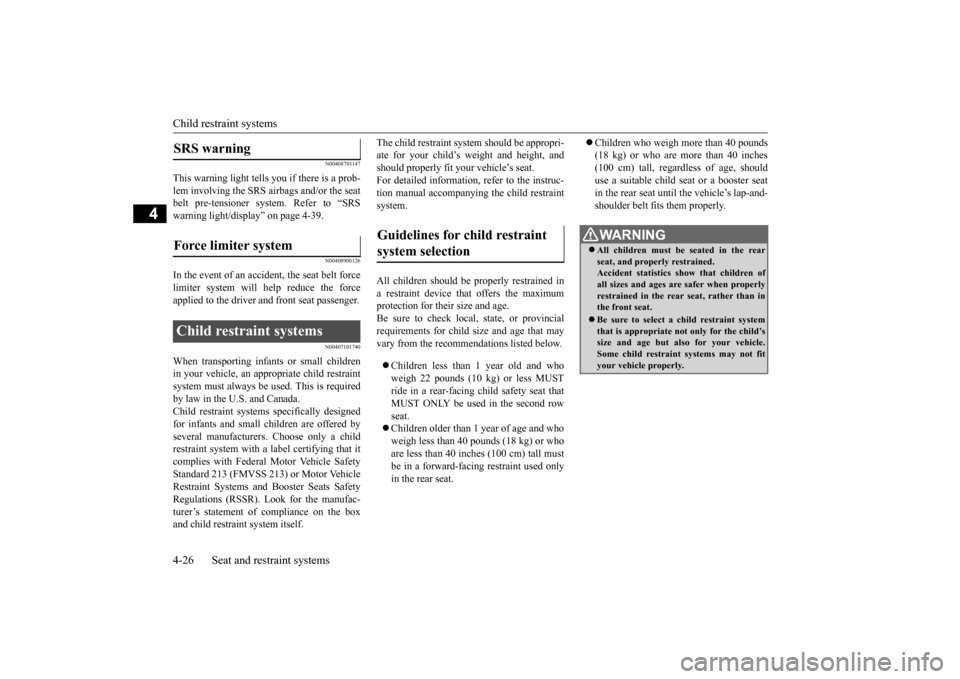
The child restraint syst
em should be appropri-
ate for your child’s weight and height, andshould properly fit your
vehicle’s seat.
For detailed information, refer to the instruc- tion manual accompanying the child restraintsystem. All children should be
properly restrained in
a restraint device that offers the maximumprotection for their size and age. Be sure to check local, state, or provincial requirements for child si
ze and age that may
vary from the recommendations listed below. Children less than 1 year old and who weigh 22 pounds (10 kg) or less MUST ride in a rear-facing ch
ild safety seat that
MUST ONLY be used in the second row seat. Children older than 1 year of age and who weigh less than 40 pounds (18 kg) or who are less than 40 inches (100 cm) tall must be in a forward-facing restraint used onlyin the rear seat.
Children who weigh more than 40 pounds (18 kg) or who are more than 40 inches(100 cm) tall, regard
less of age, should
use a suitable child seat or a booster seat in the rear seat until
the vehicle’s lap-and-
shoulder belt fits
them properly.
SRS warning Force limiter system Child restraint systems
Guidelines for child restraint system selection
WA R N I N G All children must be seated in the rear seat, and properly restrained.Accident statistics show that children of all sizes and ages are
safer when properly
restrained in the rear seat, rather than inthe front seat. Be sure to select a child restraint system that is appropriate not only for the child’s size and age but also for your vehicle. Some child restraint systems may not fityour vehicle properly.
BK0223400US.book 26 ページ 2015年2月13日 金曜日 午後12時15分
Page 77 of 464

5
Features and controlsBreak-in recommendations ..............................................................5-3 Keys .................................................................................................5-3 Electronic immobilizer (Anti-theft starting system) ........................5-4Keyless entry system (if so equipped) ..............................................5-7 Free-hand Advanced Security Tr
ansmitter (F.A.S.T.-key) (if so
equipped).....................................................................................5-12Door locks ......................................................................................5-33 Power door locks ......
...........
...........
...........
...........
...........
.........
.....5-35
Child safety locks for rear door ..........
...........
.........
.........
.........
.....5-36
Liftgate (except for vehi
cles equipped with the
power liftgate) ....5-36
Power liftgate (if so equipped) .......................................................5-38 Inside liftgate release .....................................................................5-44Theft-alarm system ........................................................................5-45 Power window control ...................................................................5-49 Sunroof (if so equipped) .................................................................5-51Parking brake .................................................................................5-53 Steering wheel height and reach adjustment ..................................5-54 Inside rearview mirror ...................................................................5-55Outside rearview mirrors ...............................................................5-57 Ignition switch ...............................................................................5-60 Steering wheel lock (if so equipped) ..............................................5-62Starting the engine .........................................................................5-62 Automatic transaxle (if so equipped)..............................................5-64 Continuously variable transmission
(CVT) (if so equipped)..........5-71
Electronically controlled
4WD system (if so equipped).................5-79
S-AWC (Super-All Wheel Control) (if
so equipped) .....................5-81
4-wheel drive operation .................................................................5-85Inspection and maintenance followi
ng rough road operation ........5-87
Cautions on the handling of 4-wheel dr
ive vehicles ..................... 5-88
Service brake ................................................................................. 5-89 Hill start assist (if so equipped) ...................................................... 5-89Brake assist system ........................................................................ 5-90 Anti-lock braking system .............................................................. 5-91 Electric power steering system (EPS) ........................................... 5-93Active stability control (ASC) ....................................................... 5-94 Cruise control (if so equipped) ....................................................... 5-96 Adaptive Cruise Control System (ACC)
(if so equipped) ............ 5-100
Forward Collision Mitigation System
(FCM) (if so equipped) .... 5-111
Lane Departure Warning System (LDW
) (if so equipped)........... 5-116
Tire pressure monitoring system ................................................. 5-119Rear-view camera (if so equipped)............................................... 5-124 Instrument cluster ........................................................................ 5-126 Multi Information display - Type 1 ............................................. 5-128Multi Information display - Type 2 ............................................. 5-146 Indicator light, warning light, and
information screen display list
(multi information display - Type 1) ....................................... 5-154Indicator and warning light package
(multi information display - Type
2) .............................................................................................. 5-171 Indicators ..................................................................................... 5-172Warning lights .............................................................................. 5-173 Information screen display (Vehicle equipped with the multi informa- tion display - Type 1) ............................................................... 5-175Combination headlights and dimmer switch ............................... 5-177 Headlight leveling switch (if so equipped)................................... 5-182 Turn signal lever .......................................................................... 5-183Hazard warning flasher switch .................................................... 5-184
BK0223400US.book 1 ページ 2015年2月13日 金曜日 午後12時15分
Page 130 of 464
Steering wheel height and reach adjustment 5-54 Features and controls
5
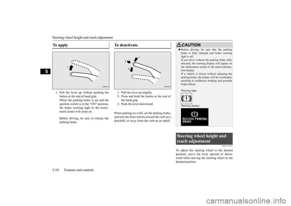
When parking on a hill, set the parking brake, and turn the front wheels toward the curb on a downhill, or away from the curb on an uphill.
N00511501241
To adjust the steering wheel to the desired position, move the lever upward or down- ward while moving the steering wheel to the desired position.
To apply 1- Pull the lever up without pushing the
button at the end of hand grip. When the parking brake is set and theignition switch is in
the “ON” position,
the brake warning light in the instru- ment cluster will come on. Before driving, be sure to release the parking brake.
To deactivate 1- Pull the lever up slightly. 2- Press and hold the button at the end of
the hand grip.
3- Push the lever downward.
CAUTION Before driving, be sure that the parking brake is fully released and brake warninglight is off.If you drive without the parking brake fully released, the warning
display will appear on
the information screen
in the multi-informa-
tion display. If a vehicle is driven without releasing the parking brake, the brakes will be overheated,resulting in ineffectiv
e braking and possible
brake failure. Warning light Warning display
Steering wheel height and reach adjustment
BK0223400US.book 54 ページ 2015年2月13日 金曜日 午後12時15分
Page 182 of 464
Adaptive Cruise Control System (ACC) (if so equipped) 5-106 Features and controls
5
N00581500027
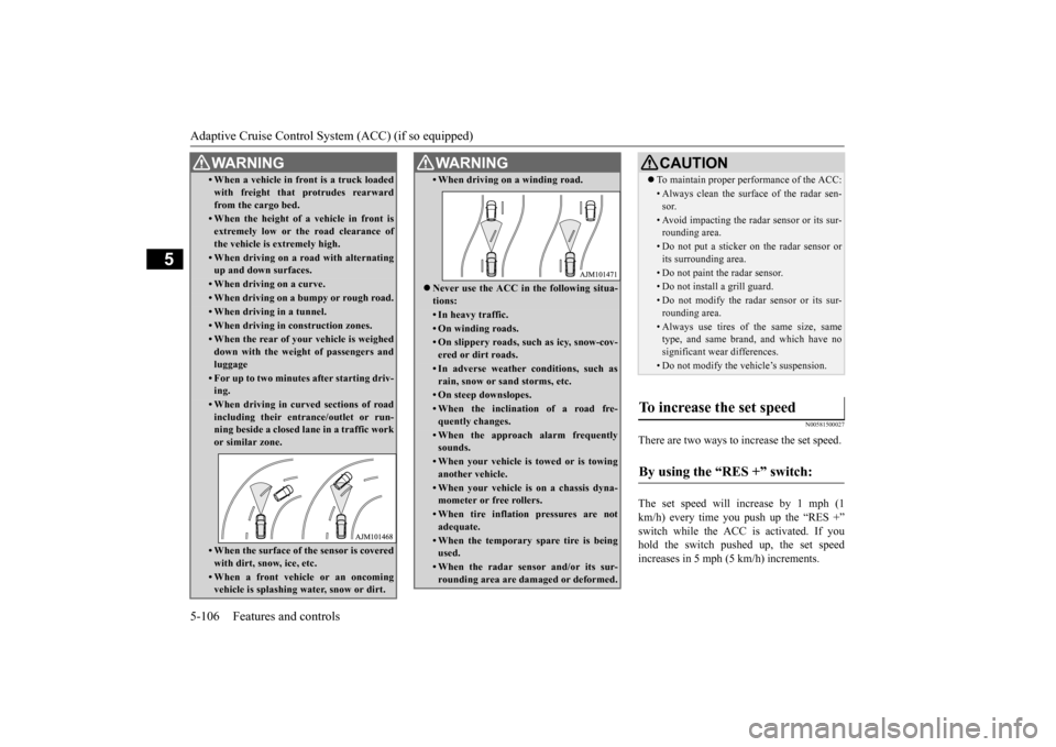
There are two ways to increase the set speed. The set speed will increase by 1 mph (1 km/h) every time you push up the “RES +” switch while the ACC is activated. If youhold the switch pushed up, the set speed increases in 5 mph (5 km/h) increments.
• When a vehicle in front is a truck loaded with freight that protrudes rearwardfrom the cargo bed.• When the height of a vehicle in front isextremely low or the road clearance ofthe vehicle is extremely high.• When driving on a r
oad with alternating
up and down surfaces.• When driving on a curve.• When driving on a bumpy or rough road.• When driving in a tunnel.• When driving in construction zones.• When the rear of your vehicle is weigheddown with the weight of passengers andluggage• For up to two minutes after starting driv-ing.• When driving in curved sections of roadincluding their entrance/outlet or run- ning beside a closed lane in a traffic work or similar zone.• When the surface of th
e sensor is covered
with dirt, snow, ice, etc.• When a front vehicle or an oncomingvehicle is splashing wa
ter, snow or dirt.
WA R N I N G
• When driving on
a winding road.
Never use the ACC in the following situa- tions:• In heavy traffic.• On winding roads.• On slippery roads, such as icy, snow-cov-ered or dirt roads.• In adverse weather conditions, such asrain, snow or sand storms, etc.• On steep downslopes.• When the inclination of a road fre-quently changes.• When the approach alarm frequentlysounds.• When your vehicle is towed or is towinganother vehicle.• When your vehicle is on a chassis dyna-mometer or free rollers.• When tire inflation pressures are notadequate.• When the temporary sp
are tire is being
used.• When the radar sensor and/or its sur-rounding area are damaged or deformed.WA R N I N G
CAUTION To maintain proper performance of the ACC:• Always clean the surface of the radar sen- sor.• Avoid impacting the radar sensor or its sur-rounding area.• Do not put a sticker on the radar sensor orits surrounding area.• Do not paint the radar sensor.• Do not install a grill guard.• Do not modify the radar sensor or its sur- rounding area.• Always use tires of the same size, sametype, and same brand, and which have no significant wear differences.• Do not modify the vehicle’s suspension.
To increase the set speed
By using the “RES +” switch:
BK0223400US.book 106 ページ 2015年2月13日 金曜日 午後12時15分
Page 189 of 464
Forward Collision Mitigation System (FCM) (if so equipped)
Features and controls 5-113
5
If the brake pedal is not depressed within 2 seconds after your vehicle has beenstopped by the FCM, a warning buzzerwill sound and the brakes activated by the FCM will automatically be released. Apply the brakes as
necessary to keep
your vehicle stationary.NOTE
When depressing the brake pedal while auto- matic braking is applie
d, the brake pedal will
feel firm. This is normal. Depress the brake pedal harder to apply
greater braking force.
During the automatic braking, operating sounds may be heard. This is normal. WA R N I N G The FCM will not activate and will not provide either warnin
g or braking in cer-
tain situations. Some of these include:• When the selector lever is in the “P”(PARK), the “R” (REVERSE), or the “N” (NEUTRAL) position.• When your vehicle speed is extremelylow, less than approximately 2 mph (2km/h).• When an object other than a vehicle,such as a pedestri
an, is in front.
• When the FCM has detected a problem in the system.WA R N I N G
• When a vehicle sudden
ly cuts in front of
your vehicle.• When the vehicle in fr
ont is moving at a
speed much lower than your vehicle’s speed.
Braking function will not work in the fol- lowing situations.• Your vehicle is driving at approximately19 mph (30 km/h) or faster while thevehicle in front is
stationary or moving
extremely slow.•ASC is OFF. The forward collision warning function and/or the FCM brakin
g function may not
activate in certain situations. Some of these include:• When a vehicle cuts
into your path at a
close distance.• When a vehicle ahead is moving at lowspeed.• When a vehicle ahead is not completelyin your path.• When a vehicle ahead
is towing a trailer.
• When a motorcycle or a bicycle is in front.• When a vehicle ahead is a truck loadedwith freight that protrudes rearward from the cargo bed.• When the height of a vehicle ahead isextremely low or its road clearance isextremely high.WA R N I N G
• When driving on a r
oad with alternating
up and down steep slopes.• When driving on a curve.• When driving on a bumpy or rough road.• When driving in a tunnel.• When the system recognizes driver’s steering, accelerati
ng, braking or gear
shifting actions as
evasive actions to
avoid collision.• When the rear of your vehicle is weigheddown with the weight of passengers and luggage• For up to two minute
s after starting driv-
ing.• In adverse weather conditions, such asrain, snow or fog.• When the surface of th
e sensor is covered
with dirt, snow and ice, etc.• When a vehicle ahea
d or an oncoming
vehicle is splashing wa
ter, snow or dirt.
When the system recognizes driver’s steering or accelerating
actions as evasive
actions to avoid collision, FCM controland alarm functions
may be canceled.
In certain situations,
though there is little
or no risk of a collision, the FCM may activate. Examples include: • When overtaking a vehicle.• When driving on a curve.WA R N I N G
BK0223400US.book 113 ページ 2015年2月13日 金曜日 午後12時15分
Page 325 of 464
Trailer towing
Driving safety 6-13
6
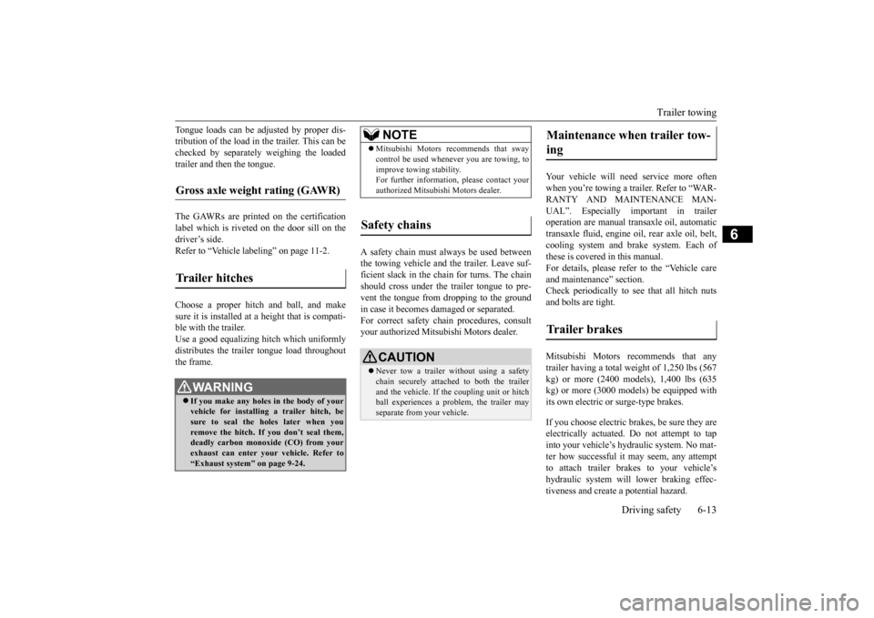
Tongue loads can be adjusted by proper dis- tribution of the load in the trailer. This can bechecked by separately
weighing the loaded
trailer and then the tongue. The GAWRs are printed on the certification label which is riveted on the door sill on the driver’s side. Refer to “Vehicle labeling” on page 11-2. Choose a proper hitch and ball, and make sure it is installed at a height that is compati- ble with the trailer.Use a good equalizing hitch which uniformly distributes the trailer tongue load throughout the frame.
A safety chain must al
ways be used between
the towing vehicle and the trailer. Leave suf-ficient slack in the chain for turns. The chain should cross under the trailer tongue to pre- vent the tongue from dropping to the groundin case it becomes damaged or separated. For correct safety chai
n procedures, consult
your authorized Mitsub
ishi Motors dealer.
Your vehicle will need service more often when you’re towing a trailer. Refer to “WAR-RANTY AND MAINTENANCE MAN- UAL”. Especially important in trailer operation are manual transaxle oil, automatictransaxle fluid, engine oi
l, rear axle oil, belt,
cooling system and brake system. Each of these is covered in this manual. For details, please refer to the “Vehicle care and maintenance” section.Check periodically to see that all hitch nuts and bolts are tight. Mitsubishi Motors recommends that any trailer having a total we
ight of 1,250 lbs (567
kg) or more (2400 models), 1,400 lbs (635kg) or more (3000 mode
ls) be equipped with
its own electric or surge-type brakes. If you choose electric br
akes, be sure they are
electrically actuated. Do not attempt to tapinto your vehicle’s hydraulic system. No mat- ter how successful it
may seem, any attempt
to attach trailer brakes to your vehicle’shydraulic system will lower braking effec- tiveness and create a potential hazard.
Gross axle weight rating (GAWR) Trailer hitches
WA R N I N G If you make any holes in the body of your vehicle for installing
a trailer hitch, be
sure to seal the holes later when youremove the hitch. If
you don’t seal them,
deadly carbon monoxide (CO) from your exhaust can enter your vehicle. Refer to“Exhaust system” on page 9-24.
NOTE
Mitsubishi Motors recommends that sway control be used whenever you are towing, toimprove towing stability.For further informati
on, please contact your
authorized Mitsubishi Motors dealer.
Safety chains
CAUTION Never tow a trailer wi
thout using a safety
chain securely attached to both the trailer and the vehicle. If the
coupling unit or hitch
ball experiences a probl
em, the trailer may
separate from
your vehicle.
Maintenance when trailer tow- ing Trailer brakes
BK0223400US.book 13 ページ 2015年2月13日 金曜日 午後12時15分
Page 414 of 464
Tires 9-16 Vehicle care and maintenance
9
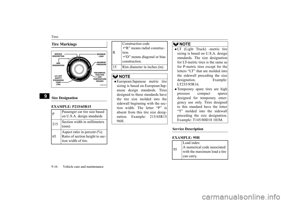
EXAMPLE: P215/65R15
EXAMPLE: 95H
Tire Markings Size Designation P
Passenger car tire size based on U.S.A. design standards
215
Section width in millimeters (mm)
65
Aspect ratio in percent (%) Ratio of section height to sec- tion width of tire.
R
Construction code •“R” means radial construc- tion. •“D” means diagonal or bias construction.
15 Rim diameter in inches (in)
NOTE
European/Japanese metric tire sizing is based on European/Jap- anese design standards. Tires designed to these standards havethe tire size molded into the sidewall beginning with the sec- tion width. The letter “P” isabsent from this tire size desig- nation. Example: 215/65R15 96H.
LT (Light Truck) -metric tiresizing is based on U.S.A. design standards. The size designation for LT-metric tires is the same asfor P-metric tires except for the letters “LT” that are molded into the sidewall preceding the sizedesignation. Example: LT235/85R16.Temporary spare tires are highpressure compact spares designed for temporary emer-gency use only. Tires designed to this standard have the letter “T” molded into the sidewallpreceding the si
ze designation.
Example: T145/80D18 103M.
Service Description 95
Load index A numerical code associated with the maximum load a tire can carry.NOTE
BK0223400US.book 16 ページ 2015年2月13日 金曜日 午後12時15分
Page 450 of 464
Vehicle dimensions 11-4 Specifications
11
N01147501593
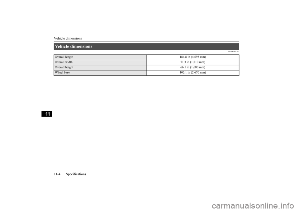
Vehicle dimensions Overall length
184.8 in (4,695 mm)
Overall width
71.3 in (1,810 mm)
Overall height
66.1 in (1,680 mm)
Wheel base
105.1 in (2,670 mm)
BK0223400US.book 4 ページ 2015年2月13日 金曜日 午後12時15分