Page 97 of 223
 programmed settings of the buttons on the
interior rearview mirror are deleted.3.Hold the hand-held transmitter of the sys‐
tem to be operated a distance of approx. 1
to 3 in/2.5 to 8 cm away from t")
programmed settings of the buttons on the
interior rearview mirror are deleted.3.Hold the hand-held transmitter of the sys‐
tem to be operated a distance of approx. 1
to 3 in/2.5 to 8 cm away from the buttons
on the interior rearview mirror. The re‐
quired distance depends on the particular
hand-held transmitter.4.Press the button of the desired function on
the hand-held transmitter and the button
being programmed on the interior rearview
mirror simultaneously and hold. The LED on
the interior rearview mirror flashes slowly at
first.5.When the LED flashes more rapidly, release
both buttons. Rapid flashing indicates that
the button on the interior rearview mirror
has been programmed.
If the LED does not flash faster after 60 sec‐
onds, change the distance between the in‐
terior rearview mirror and the hand-held
transmitter and repeat the step. Multiple
trials at different distances may be neces‐
sary. Wait at least 15 seconds between tri‐
als.6.To program additional functions on other
buttons, repeat steps 3 to 5.
The systems can be operated with the buttons
on the interior rearview mirror.
Special characteristics of alternating-
code radio systems
If the system cannot be operated after re‐
peated programming, check whether the sys‐
tem to be operated uses an alternating-code
system.
Read the operating instructions of the system
or press and hold the programmed button on
the interior rearview mirror. If the LED on the
interior rearview mirror flashes rapidly at first
and then lights up continuously for 2 seconds,
the system is equipped with an alternating-
code system. This flashing LED pattern repeats
itself for approx. 20 seconds.
In systems with an alternating-code system, the
universal garage door opener and the system
must be additionally synchronized.
Please obtain additional information on syn‐
chronization in the operating instructions of the
system being set up.
The systems will be easier to synchronize with
the aid of a second person.
Synchronization:1.Park the vehicle within range of the re‐
mote-controlled system.2.Program the corresponding button on the
interior rearview mirror as described.3.Identify and press the synchronization but‐
ton on the system being set up. You have
approx. 30 seconds for the next step.4.Press and hold the button on the interior
rearview mirror for approx. 3 seconds and
then release it. Repeat this step up to three
times if necessary to complete the synchro‐
nization procedure. When synchronization
is completed, the programmed function is
executed.
Reprogramming individual buttons
1.Switch on the ignition.2.Hold the hand-held transmitter at a dis‐
tance of approx. 1 to 3 in/2.5 to 8 cm from
the memory buttons.
The required distance depends on the par‐
ticular hand-held transmitter.3.Press the memory button of the universal
garage door opener.4.If the LED flashes slowly after approx.
20 seconds, press the transmit button on
the hand-held transmitter.5.Release both buttons when the LED flashes
rapidly.
If the LED does not flash rapidly after ap‐
prox. 60 seconds, change the distance and
repeat the step.Seite 97Interior equipmentCONTROLS97
Online Edition for Part no. 01 40 2 964 433 - VI/15
Page 98 of 223
 Canada: if the LED does not flash rapidly af‐
ter approx. 60 seconds, change the dis‐
tance and repeat the step. If programming
was aborted by the hand-held transmitter,
hold down the memory butto")
Canada: if the LED does not flash rapidly af‐
ter approx. 60 seconds, change the dis‐
tance and repeat the step. If programming
was aborted by the hand-held transmitter,
hold down the memory button and press
and release the button on the hand-held
transmitter several times for 2 seconds.
Controls
WARNING
Body parts can be jammed when operat‐
ing remote-controlled systems, e.g. the garage
door, using the universal garage door opener.
There is risk of injuries or risk of property dam‐
age. Make sure that the area of movement of
the respective system is clear during program‐
ming and operation. Also follow the safety in‐
structions of the hand-held transmitter. ◀
The system, such as the garage door, can be
operated using the button on the interior rear‐
view mirror with the engine running or the igni‐
tion switched on. When you are within the re‐
ception range of the system, press and hold the
button until the function is initiated. The LED on
the interior rearview mirror lights up continu‐
ously while the radio signal is being transmit‐
ted.
Deleting stored functions
Press the right and left buttons on the interior
rearview mirror simultaneously for approx.
20 seconds until the LED flashes rapidly. All
stored functions are deleted. The functions can‐
not be deleted individually.
Sun visor Glare protection
Folding down
Fold the sun visor down.
Folding up
Fold the sun visor up.
Glare protection from the side
Folding down1.Fold the sun visor down.2.Detach from the holder and pivot sideways
to the side window.
Folding up
To close the sun visor, proceed in reverse order.
Vanity mirror A vanity mirror is located behind a cover on
each sun visor.
To open, fold the cover up.
Depending on the vehicle equipment, mirror
lighting comes on when the cover is opened.
Digital compass
1Adjustment button on the back of the mir‐
ror2Display
The display shows the main or secondary com‐
pass direction in which the vehicle is traveling.
Operating concept
Various functions can be called up by pressing
the adjustment button with a pointed object
such as a pen. The following adjustment op‐
tions are displayed one after the other, de‐
Seite 98CONTROLSInterior equipment98
Online Edition for Part no. 01 40 2 964 433 - VI/15
Page 99 of 223
 pending on how long the adjustment button is
pressed:▷Press briefly: switch the display on/off.▷3 to 6 seconds: set the compass zone.▷6 to 9 seconds: calibrate the compass.▷9 to 12 seconds: se")
pending on how long the adjustment button is
pressed:▷Press briefly: switch the display on/off.▷3 to 6 seconds: set the compass zone.▷6 to 9 seconds: calibrate the compass.▷9 to 12 seconds: set left-hand/right hand
steering.▷12 to 15 seconds: set the language.
Setting compass zones
Set the compass zone corresponding to the ve‐
hicle's geographic location so that the compass
can function correctly; refer to the world map
with compass zones.
Press the adjustment button for 3‑4 seconds.
The number of the compass zone set is shown
in the display.
To change the zone setting, briefly press the
adjustment button repeatedly until the display
shows the number of the compass zone corre‐
sponding to the current location.
The compass is operational again after approx.
10 seconds.
Calibrating the digital compass The digital compass must be calibrated in the
following situations:▷An incorrect compass direction is shown.▷The cardinal direction displayed does not
change even if the direction of travel
changes.▷Not all compass directions are shown.
Procedure
1.Make sure that there are no large metal ob‐
jects or overhead power lines in the vicinity
of the vehicle and that there is enough
space to drive in a circle.2.Set the currently valid compass zone.3.Press the adjustment button for 6‑7 sec‐
onds to call up C. Then drive at least one full
circle at a maximum speed of
4 mph/7 km/h. When the system is cali‐
brated, the C is replaced by the compass di‐
rections.Seite 99Interior equipmentCONTROLS99
Online Edition for Part no. 01 40 2 964 433 - VI/15
Page 100 of 223
 Right-hand/left-hand steering
The digital compass is set for right-hand or left-
hand steering at the factory.
Setting the language
Press the adjustment button for 12‑13 seconds.
Briefly press the a")
Right-hand/left-hand steering
The digital compass is set for right-hand or left-
hand steering at the factory.
Setting the language
Press the adjustment button for 12‑13 seconds.
Briefly press the adjustment button again to
switch between English "E" and German "O".
The setting is automatically saved after approx.
10 seconds.
Cupholders and ashtray/
lighter
Cupholders
Two cupholders are located in the center con‐
sole in the front.
MINI Countryman: two additional cupholders
are located at the end of the center console in
the rear. Additional cupholders can be installed
on the center rail.
MINI Paceman: additional cupholders are lo‐
cated in the console between the rear seats.
Depending on the equipment, additional cu‐
pholders can be installed on the center rail.
WARNING
Unsuitable containers in the cup holder
and hot beverages can damage the cup holder
and increase the risk of injuries in the event of
an accident. There is risk of injuries or risk of
property damage. Use light-weight, unbreaka‐
ble, and sealable containers. Do not transport
hot beverages. Do not force objects into the
cup holder. ◀
Ashtray
The ashtray is located in one of the cupholders
in the center console at the front.
EmptyingTake out the entire ashtray, arrow.
When installing, ensure that the ashtray is in‐
serted in the cupholder with the adapter.
Lighter
With the engine running or the ignition
switched on, press in the cigarette lighter.
Seite 100CONTROLSInterior equipment100
Online Edition for Part no. 01 40 2 964 433 - VI/15
Page 101 of 223
 The lighter can be removed as soon as it pops
back out.
WARNING
Contact with hot heating elements or the
hot socket of the cigarette lighter can cause
burns. Flammable materials can ignite if the
ciga")
The lighter can be removed as soon as it pops
back out.
WARNING
Contact with hot heating elements or the
hot socket of the cigarette lighter can cause
burns. Flammable materials can ignite if the
cigarette lighter falls down or is held against
the respective objects. There is risk of fire and
injuries. Hold the cigarette lighter on its handle.
Make sure that children do not use the ciga‐
rette lighter and do not burn themselves, e.g.
by carrying the remote control along when ex‐
iting the vehicle. ◀
Connecting electrical de‐
vices
The lighter socket can be used as a socket for
electrical equipment while the engine is run‐
ning or when the ignition is switched on. The
total load of all sockets must not exceed
140 watts at 12 volt.
Avoid damaging the sockets by attempting to
insert plugs of unsuitable shape or size.
CAUTION
Battery chargers for the vehicle battery
can work with high voltages and currents,
which means that the 12V on-board network
can be overloaded or damaged. There is risk of
property damage. Only connect battery charg‐
ers for the vehicle battery to the starting aid
terminals in the engine compartment. ◀
CAUTION
If metal objects fall into the socket, they
can cause a short circuit. There is risk of prop‐
erty damage. Replace the cigarette lighter or socket cover again after using the socket. ◀
Socket in the center console Remove the cover or lighter, refer to page 100,
from the socket.Socket in the rear
MINI Countryman
Take out the cover.
MINI Paceman
Take out the cover.
Socket in the cargo area
MINI Countryman
Take out the cover.
Seite 101Interior equipmentCONTROLS101
Online Edition for Part no. 01 40 2 964 433 - VI/15
Page 102 of 223
 MINI Paceman
Take out the cover.
Cargo area Cargo cover WARNING
Loose objects in the cars interior can be
thrown into the cars interior while driving, e.g.
in the event of an accident or during brak")
MINI Paceman
Take out the cover.
Cargo area Cargo cover WARNING
Loose objects in the car's interior can be
thrown into the car's interior while driving, e.g.
in the event of an accident or during braking
and evasive maneuvers. There is risk of injuries.
Secure loose objects in the car's interior. ◀
When the tailgate is opened, the cargo cover is
raised.
When closing, ensure that the cargo cover is
resting on the rubber buffers of the securing
straps; otherwise, damage may occur when
closing the tailgate.
To load bulky luggage, the cover can be re‐
moved.
1.Detach the securing straps from the tail‐
gate.2.Lift the cover slightly, arrow 1, and pull it
back and out of the bracket, arrow 2.
MINI Countryman:
MINI Paceman:
MINI Countryman: rear seat backrests
Observe the instructions concerning the safety
belt, refer to page 38. Otherwise, personal pro‐
tection may be compromised.
WARNING
Danger of jamming with folding down the
backrests. There is risk of injuries or risk of property damage. Make sure that the area of
movement of the rear backrest is clear prior to
folding down. ◀
The rear seat backrest is divided at a ratio of
40-20-40.
When the outer rear seat backrests are folded down, it is not permissible for a person to travel
on the center seat.
Remove the third head restraint, refer to
page 42, if necessary.
Open the center safety belt and insert it in the
belt holder on the headliner, refer to page 40.
Enlarge the cargo area by adjusting the rear
seat backrests to a more upright position.
Seite 102CONTROLSInterior equipment102
Online Edition for Part no. 01 40 2 964 433 - VI/15
Page 103 of 223
 The backrests can be adjusted to 10 different
positions between the comfort and transport
positions and they can be folded down.
In the comfort position, the backrests are tilted
back to the greatest")
The backrests can be adjusted to 10 different
positions between the comfort and transport
positions and they can be folded down.
In the comfort position, the backrests are tilted
back to the greatest possible angle and in the
transport position they are nearly vertical.
Before beginning with the mounting of a child
restraint fixing system, note the instructions,
refer to page 45.1.Hold the top of the backrest, for example
the head restraint, and pull on the loop, ar‐
row.2.Engage the backrest in the desired position
or fold it down.
Folding the backrests back up
WARNING
With an unlocked backrest, an unsecured
load can be thrown into the car's interior, e.g.
in case of an accident, braking or evasive ma‐
neuver. There is risk of injuries. Make sure that
the backrest engages into the locking after
folding it back. ◀
WARNING
The stability of the child restraint system
is limited or compromised with incorrect seat
adjustment or improper installation of the child
seat. There is risk of injuries or danger to life.
Make sure that the child restraint system fits
securely against the backrest. If possible, adjust
the backrest tilt for all affected backrests and
correctly adjust the seats. Make sure that seats
and backrests are securely engaged. If possible,
adjust the height of the head restraints or re‐
move them. ◀
When the backrests are folded back up, they
engage in the transport position.
To set the desired backrest inclination or com‐
fort position, hold the backrest, pull the loop
forward, and adjust the backrest.
MINI Paceman: rear seat backrests1.Fold the belt buckles down.2.Pull on the respective loop, arrow.
The backrest is unlocked.3.Fold the backrest forward.
Folding the backrests back up Hold the top of the backrest, for example the
head restraint, and fold it back.
WARNING
With an unlocked backrest, an unsecured
load can be thrown into the car's interior, e.g.
in case of an accident, braking or evasive ma‐
neuver. There is risk of injuries. Make sure that
the backrest engages into the locking after
folding it back. ◀
Seite 103Interior equipmentCONTROLS103
Online Edition for Part no. 01 40 2 964 433 - VI/15
Page 104 of 223
 Flat loading floor
The maximum load on the loading floor is:
330 lbs, 150 kg.
Access to storage area
A storage area for items like the partition net is
found under the loading floor.1.Reach into the r")
Flat loading floor
The maximum load on the loading floor is:
330 lbs, 150 kg.
Access to storage area
A storage area for items like the partition net is
found under the loading floor.1.Reach into the recess, arrow 1, on the rear
edge of the loading floor.2.Lift the loading floor at the rear, arrow 1,
and fold it forward, arrow 2.
MINI Countryman:
MINI Paceman:
Before closing the tailgate, lower the loading
floor back onto the cargo area floor.
Removing
The loading floor can be removed if necessary.
1.Fold up the loading floor.2.Pull it back slightly and out of the holders.3.Then remove it upward.
The folded loading floor can be stored in the
cargo area.
MINI Countryman: partition net
Before installing1.Remove the pouch with the partition net
from the storage compartment under the
loading floor in the cargo area.2.Take the partition net out of the pouch, un‐
roll it, and unfold it.
After use, fold and roll up the partition net
in the same manner and place it in the
pouch so that it can be stowed back under
the cargo floor panel. Ensure that hooks
and tensioning buckles do not rest on the
rod elements.3.Unfold the partition net to the point where
the rod elements engage.
Installation behind the front seats
1.Take out the cargo cover if necessary.2.Fold down the rear seat backrests, refer to
Enlarging the cargo area.3.Insert the retaining pins of the partition net
all the way into the front holders in the
headliner, arrow 1, and push forward.4.Attach the hooks, arrow 2, at the bottom of
the retaining straps on both sides to the
eyelets on the vehicle floor. Firmly attach
the partition net.5.Lash the partition net tightly. To do this,
tighten the retaining straps using the ten‐
sioning buckles.Seite 104CONTROLSInterior equipment104
Online Edition for Part no. 01 40 2 964 433 - VI/15
 1
1 2
2 3
3 4
4 5
5 6
6 7
7 8
8 9
9 10
10 11
11 12
12 13
13 14
14 15
15 16
16 17
17 18
18 19
19 20
20 21
21 22
22 23
23 24
24 25
25 26
26 27
27 28
28 29
29 30
30 31
31 32
32 33
33 34
34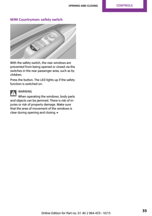 35
35 36
36 37
37 38
38 39
39 40
40 41
41 42
42 43
43 44
44 45
45 46
46 47
47 48
48 49
49 50
50 51
51 52
52 53
53 54
54 55
55 56
56 57
57 58
58 59
59 60
60 61
61 62
62 63
63 64
64 65
65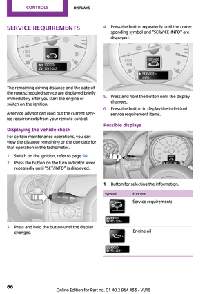 66
66 67
67 68
68 69
69 70
70 71
71 72
72 73
73 74
74 75
75 76
76 77
77 78
78 79
79 80
80 81
81 82
82 83
83 84
84 85
85 86
86 87
87 88
88 89
89 90
90 91
91 92
92 93
93 94
94 95
95 96
96 97
97 98
98 99
99 100
100 101
101 102
102 103
103 104
104 105
105 106
106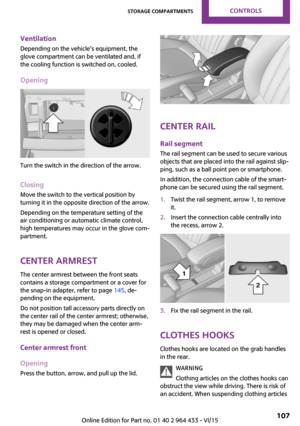 107
107 108
108 109
109 110
110 111
111 112
112 113
113 114
114 115
115 116
116 117
117 118
118 119
119 120
120 121
121 122
122 123
123 124
124 125
125 126
126 127
127 128
128 129
129 130
130 131
131 132
132 133
133 134
134 135
135 136
136 137
137 138
138 139
139 140
140 141
141 142
142 143
143 144
144 145
145 146
146 147
147 148
148 149
149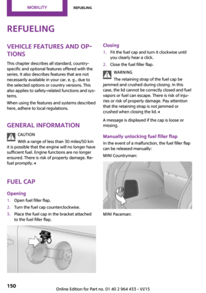 150
150 151
151 152
152 153
153 154
154 155
155 156
156 157
157 158
158 159
159 160
160 161
161 162
162 163
163 164
164 165
165 166
166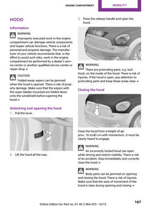 167
167 168
168 169
169 170
170 171
171 172
172 173
173 174
174 175
175 176
176 177
177 178
178 179
179 180
180 181
181 182
182 183
183 184
184 185
185 186
186 187
187 188
188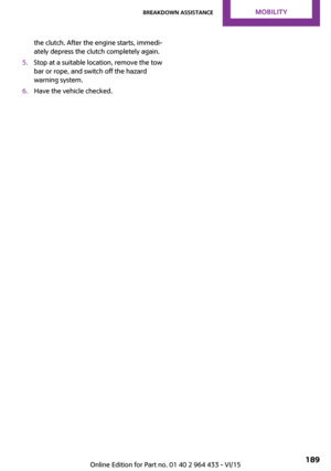 189
189 190
190 191
191 192
192 193
193 194
194 195
195 196
196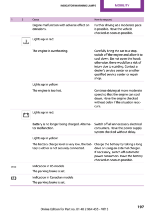 197
197 198
198 199
199 200
200 201
201 202
202 203
203 204
204 205
205 206
206 207
207 208
208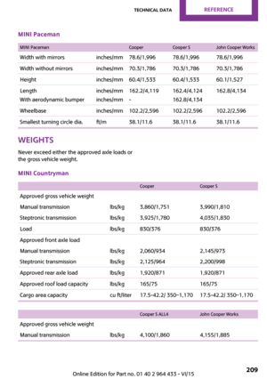 209
209 210
210 211
211 212
212 213
213 214
214 215
215 216
216 217
217 218
218 219
219 220
220 221
221 222
222