2016 MERCEDES-BENZ SL-CLASS ROADSTER warning lights
[x] Cancel search: warning lightsPage 286 of 614
Useful information
i
These operating instructions describe all
the standard and optional equipment of
your COMAND system, as available at the
time of going to print. Country-specific dif-
ferences are possible. Please note that
your COMAND system may not be equip-
ped with all the features described. This
also applies to safety-related systems and
functions.
iRead the information on qualified special-
ist workshops: (
Ypage 34).
Operating safety
Important safety notes
GWARNING
Modifications to electronic components, their software as well as wiring can impair their
function and/or the function of other net-
worked components. In particular, systems
relevant to safety could also be affected. As a
result, these may no longer function as inten-
ded and/or jeopardize the operating safety of
the vehicle. There is an increased risk of an
accident and injury.
Never tamper with the wiring as well as elec-
tronic components or their software. You
should have all work to electrical and elec-
tronic equipment carried out at a qualified
specialist workshop.
If you make any changes to the vehicle elec-
tronics, the general operating permit is ren-
dered invalid.
GWARNING
If you operate information systems and com-
munication equipment integrated in the vehi-
cle while driving, you will be distracted from
traffic conditions. You could also lose control
of the vehicle. There is a risk of an accident.
Only operate the equipment when the traffic
situation permits. If you are not sure that this
is possible, park the vehicle paying attention
to traffic conditions and operate the equip-
ment when the vehicle is stationary.
You must observe the legal requirements for
the country in which you are currently driving
when operating COMAND.
COMAND calculates the route to the destina-
tion without taking account of the following,
for example:
Rtraffic lights
Rstop and yield signs
Rmerging lanes
Rparking or stopping in a no parking/no
stopping zone
Rother road and traffic rules and regulations
Rnarrow bridges
COMAND can give incorrect navigation com-
mands if the actual street/traffic situation
does not correspond with the digital map's
data. Digital maps do not cover all areas nor
all routes in an area. For example, a route may
have been diverted or the direction of a one-
way street may have changed.
For this reason, you must always observe
road and traffic rules and regulations during
your journey. Road and traffic rules and reg-
ulations always have priority over the sys-
tem's driving recommendations.
Navigation announcements are intended to
direct you while driving without diverting your
attention from the road and driving.
Please always use this feature instead of con-
sulting the map display for directions. Look-
ing at the icons or map display can distract
you from traffic conditions and driving, and
increase the risk of an accident.
Bear in mind that at a speed of only 30 mph
(approximately 50 km/h) your vehicle covers
a distance of 44 feet (approximately 14 m)
per second.
This equipment complies with FCC radiation
exposure limits set forth for uncontrolled
equipment and meets the FCC radio fre-
284Operating safety
COMAND
Page 322 of 614
For further information on the rear view cam-
era, see the vehicle Operator's Manual.
XPress theWbutton.
The system menu appears.
XSelect Settingsby turning cVdthe
COMAND controller and press Wto con-
firm.
XSelect RearViewCameraand press Wto
confirm.
XSelect Activation by R gearand press
W to confirm.
The function is switched on Oor off ª,
depending on the previous status.
Night View Assist Plus
On vehicles with Night View Assist Plus you
can have the image from Night View Assist
Plus shown on the COMAND display.
XSwitch on COMAND (Ypage 297).
XActivate Night View Assist Plus, see the
separate operating instructions.
The image from Night View Assist Plus
appears in the COMAND display.
XTo adjust the brightness: selectBright‐
nessby turning cVdthe COMAND con-
troller and press Wto confirm.
XTurn cVd the COMAND controller and
press Wto confirm.
XSwitching automatic activation on/off:
select Night
ViewAssistAuto.Acti‐
vationand press Wto confirm.
Switch the option on Oor off ª.
Option switched on: while using other func-
tions e.g. the navigation system, Night View Assist Plus is active in the background. In
the dark, in unlit surroundings and at
speeds in excess of 37 mph (60 km/h), the
Night View image is automatically dis-
played as soon as pedestrians or animals
are detected.
XTo switch off the display: selectBackand
press Wto confirm or press the kbut-
ton.
Navigation
Your COMAND equipment
These operating instructions describe all the
standard and optional equipment for your
COMAND system, as available at the time of
going to print. Country-specific differences
are possible. Please note that your
COMAND system may not be equipped with
all the features described.
Introduction
Important safety notes
GWARNING
If you operate information systems and com-
munication equipment integrated in the vehi-
cle while driving, you will be distracted from
traffic conditions. You could also lose control
of the vehicle. There is a risk of an accident.
Only operate the equipment when the traffic
situation permits. If you are not sure that this
is possible, park the vehicle paying attention
to traffic conditions and operate the equip-
ment when the vehicle is stationary.
You must observe the legal requirements for
the country in which you are currently driving
when operating COMAND.
COMAND calculates the route to the destina-
tion without taking account of the following,
for example:
Rtraffic lights
Rstop and yield signs
Rmerging lanes
Rparking or stopping in a no parking/no
stopping zone
Rother road and traffic rules and regulations
Rnarrow bridges
320Navigation
COMAND
Page 519 of 614
!Only close the trunk once the roof is low-
ered completely. Otherwise, you could
damage the roof.
If you close the trunk lid before the roof is
lowered completely, the loading aid switch
lights up and a warning tone sounds.
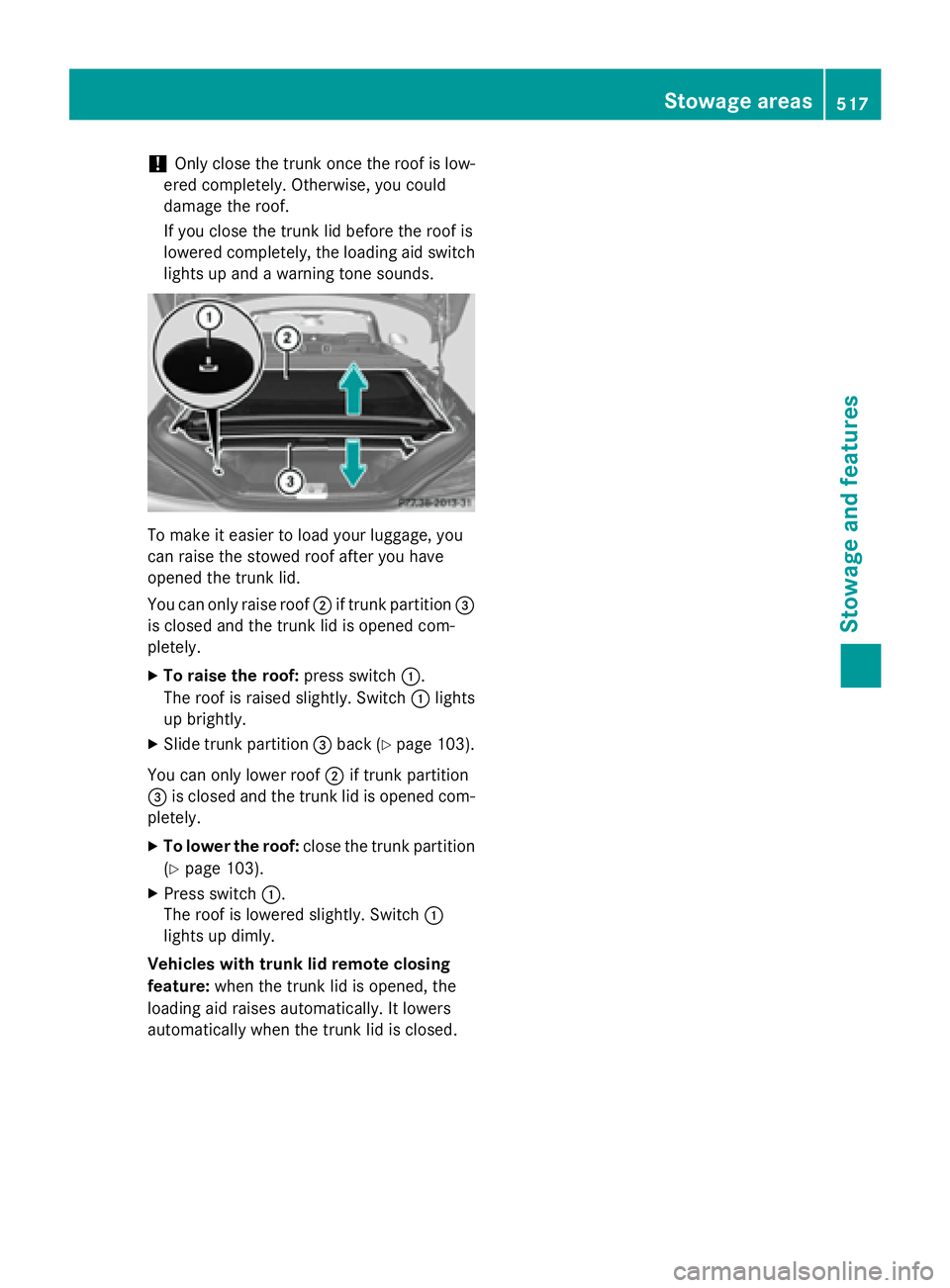
To make it easier to load your luggage, you
can raise the stowed roof after you have
opened the trunk lid.
You can only raise roof ;if trunk partition =
is closed and the trunk lid is opened com-
pletely.
XTo raise the roof: press switch:.
The roof is raised slightly. Switch :lights
up brightly.
XSlide trunk partition =back (Ypage 103).
You can only lower roof ;if trunk partition
= is closed and the trunk lid is opened com-
pletely.
XTo lower the roof: close the trunk partition
(
Ypage 103).
XPress switch :.
The roof is lowered slightly. Switch :
lights up dimly.
Vehicles with trunk lid remote closing
feature: when the trunk lid is opened, the
loading aid raises automatically. It lowers
automatically when the trunk lid is closed.
Stowage areas517
Stowage and features
Z
Page 532 of 614
Certain garage door drives are incompatible
with the integrated garage door opener. Ifyou
have difficulty programing the integrated
garage door opener, contact an authorized
Mercedes-Benz Center.
Alternatively, you can call the following tele-
phone assistance services:
RUSA: Mercedes-Benz Customer Assistance
Center at 1-800-FOR-MERCedes
RCanada: Customer Service at
1-800-387-0100
RHomeLink®hotline 1-800-355-3515 (free
of charge)
More information on HomeLink
®and /or
compat ibleproducts isalso available online
at http:/ /www.homelin k.com.
Notes on the declaration of conformity
(
Ypage 34).
USA: FCC ID: CB2HMIHL4
Canada: IC: 279B-HMIHL4
Important safety notes
GWARNING
When you operate or program the garage door
with the integrated garage door opener, per-
sons in the range of movement of the garage
door can become trapped or struck by the
garage door. There is a risk of injury.
When using the integrated garage door
opener, always make sure that nobody is
within the range of movement of the garage
door.
GWARNING
Combustion engines emit poisonous exhaust
gases such as carbon monoxide. Inhaling
these exhaust gases leads to poisoning. There
is a risk of fatal injury. Therefore never leave
the engine running in enclosed spaces with-
out sufficient ventilation.
Programming
Programing buttons
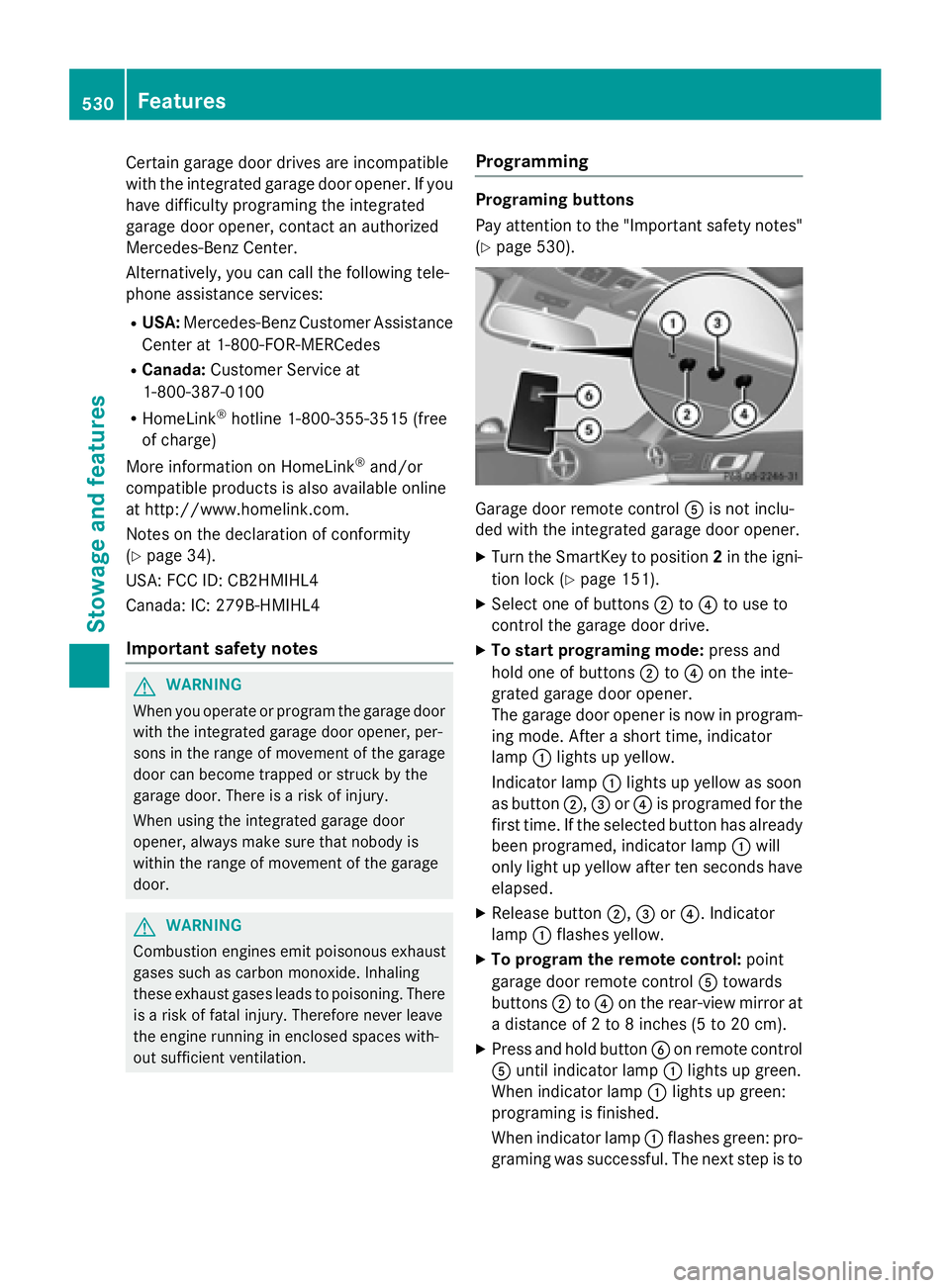
Pay attention to the "Important safety notes"
(
Ypage 530).
Garage door remote control Ais not inclu-
ded with the integrated garage door opener.
XTurn the SmartKey to position 2in the igni-
tion lock (
Ypage 151).
XSelect one of buttons ;to? to use to
control the garage door drive.
XTo start programing mode: press and
hold one of buttons ;to? on the inte-
grated garage door opener.
The garage door opener is now in program-
ing mode. After a short time, indicator
lamp :lights up yellow.
Indicator lamp :lights up yellow as soon
as button ;,=or? is programed for the
first time. If the selected button has already
been programed, indicator lamp :will
only light up yellow after ten seconds have
elapsed.
XRelease button ;,=or?. Indicator
lamp :flashes yellow.
XTo program the remote control: point
garage door remote control Atowards
buttons ;to? on the rear-view mirror at
a distance of 2 to 8 inches (5 to 20 cm).
XPress and hold button Bon remote control
A until indicator lamp :lights up green.
When indicator lamp :lights up green:
programing is finished.
When indicator lamp :flashes green: pro-
graming was successful. The next step is to
530Features
Stowage and features
Page 535 of 614
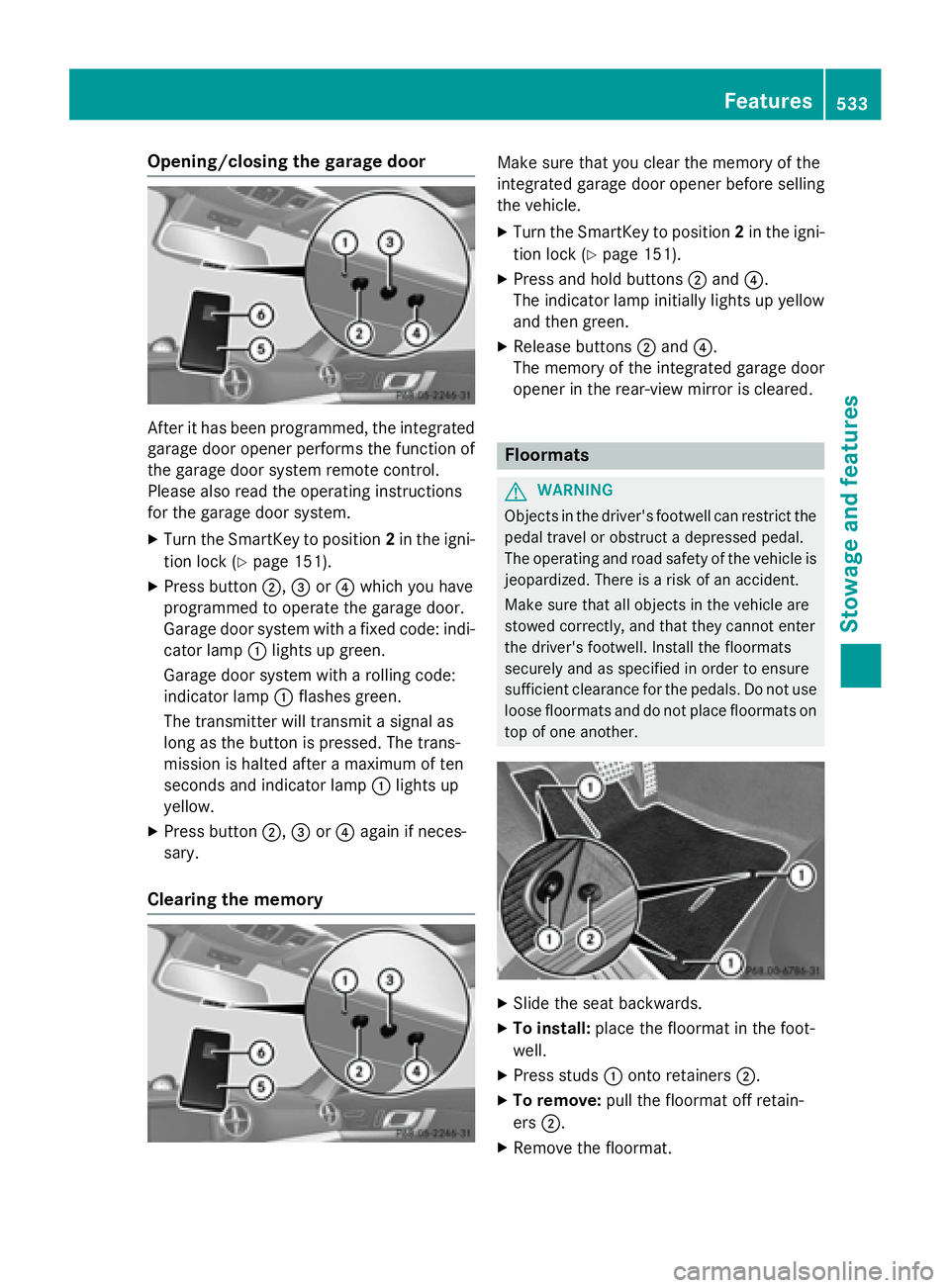
Opening/closing the garage door
After it has been programmed, the integrated
garage door opener performs the function of
the garage door system remote control.
Please also read the operating instructions
for the garage door system.
XTurn the SmartKey to position2in the igni-
tion lock (
Ypage 151).
XPress button ;,=or? which you have
programmed to operate the garage door.
Garage door system with a fixed code: indi-
cator lamp :lights up green.
Garage door system with a rolling code:
indicator lamp :flashes green.
The transmitter will transmit a signal as
long as the button is pressed. The trans-
mission is halted after a maximum of ten
seconds and indicator lamp :lights up
yellow.
XPress button ;,=or? again if neces-
sary.
Clearing the memory
Make sure that you clear the memory of the
integrated garage door opener before selling
the vehicle.
XTurn the SmartKey to position 2in the igni-
tion lock (
Ypage 151).
XPress and hold buttons ;and ?.
The indicator lamp initially lights up yellow
and then green.
XRelease buttons ;and ?.
The memory of the integrated garage door
opener in the rear-view mirror is cleared.
Floormats
GWARNING
Objects in the driver's footwell can restrict the pedal travel or obstruct a depressed pedal.
The operating and road safety of the vehicle is
jeopardized. There is a risk of an accident.
Make sure that all objects in the vehicle are
stowed correctly, and that they cannot enter
the driver's footwell. Install the floormats
securely and as specified in order to ensure
sufficient clearance for the pedals. Do not use
loose floormats and do not place floormats on
top of one another.
XSlide the seat backwards.
XTo install: place the floormat in the foot-
well.
XPress studs :onto retainers ;.
XTo remove:pull the floormat off retain-
ers ;.
XRemove the floormat.
Features533
Stowage and features
Z
Page 545 of 614
Observe the legal requirements in all coun-
tries concerned.
XDo not use hot water and do not wash the
vehicle in direct sunlight.
XUse a soft sponge to clean.
XUse a mild cleaning agent, such as a car
shampoo approved by Mercedes-Benz.
XThoroughly hose down the vehicle with a
gentle jet of water.
XDo not point the water jet directly towardsthe air inlet.
XUse plenty of water and rinse out the
sponge frequently.
XRinse the vehicle with clean water and dry
thoroughly with a chamois.
XDo not let the cleaning agent dry on the
paintwork.
When using the vehicle in winter, remove all
traces of road salt deposits carefully and as
soon as possible.
Power washers
GWARNING
The water jet from a circular jet nozzle (dirt
blasters) can cause invisible exterior damage
to the tires or chassis components. Compo-
nents damaged in this way may fail unexpect-
edly. There is a risk of an accident.
Do not use power washers with circular jet
nozzles to clean the vehicle. Have damaged
tires or chassis components replaced imme-
diately.
!Always maintain a distance of at least
11.8 in (30 cm) between the vehicle and the
power washer nozzle. Information about
the correct distance is available from the
equipment manufacturer.
Move the power washer nozzle around
when cleaning your vehicle.
Do not aim directly at any of the following:
Rtires
Rdoor gaps, roof gaps, joints, etc.
Relectrical components
Rbattery
Rconnectors
Rlights
Rseals
Rtrim
Rventilation slots
Damaged seals or electrical components
can lead to leaks or failures.
!Vehicles with HANDS-FREE ACCESS: if a
SmartKey with KEYLESS-GO is within the
detection range of the KEYLESS-GO
antenna, the following situations could lead
to the unintentional opening of the trunk
lid:
Rusing a car wash
Rusing a power washer
Make sure that the SmartKey is at least
6.5 ft (2 m) away from the vehicle.
!Mille Miglia special model: parts of your
vehicle are covered with a decorative foil.
Maintain a distance of at least 70 cm
between the foil-wrapped parts of the vehi-
cle and the nozzle of the power washer.
Information about the correct distance is
available from the equipment manufac-
turer.
Move the power washer nozzle around
when cleaning your vehicle.
Cleaning the paintwork
!Do not affix:
Rstickers
Rfilms
Rmagnetic plates or similar items
to painted surfaces. You could otherwise
damage the paintwork.
Scratches, corrosive deposits, areas affected
by corrosion and damage caused by inade-
quate care cannot always be completely
repaired. In such cases, visit a qualified spe-
cialist workshop.
Care543
Maintenance and care
Z
Page 578 of 614

remain continuously illuminated. This
sequence will be repeated every time the vehi-
cle is started as long as the malfunction
exists.
When the malfunction indicator is illuminated,
the system may not be able to detect or signal
low tire pressure as intended. TPMS malfunc-
tions may occur for a variety of reasons,
including the mounting of incompatible
replacement or alternate tires or wheels on
the vehicle that prevent the TPMS from func-
tioning properly. Always check the TPMS mal-
function telltale after replacing one or more
tires or wheels on your vehicle to ensure that the replacement or alternate tires and wheels
allow the TPMS to continue to function prop-
erly.
It is the driver's responsibility to set the tire
pressure to that recommended for cold tires
which is suitable for the operating situation
(
Ypage 571). Note that the correct tire pres-
sure for the current operating situation must
first be taught-in to the tire pressure monitor.
If there is a substantial loss of pressure, the
warning threshold for the warning message is
aligned to the reference values taught-in.
Restart the tire pressure monitor after adjust-
ing the pressure of the cold tires
(
Ypage 577). The current pressures are
saved as new reference values. As a result, a
warning message will appear if the tire pres-
sure drops significantly.
The tire pressure monitor does not warn you
of an incorrectly set tire pressure. Observe
the notes on the recommended tire pressure
(
Ypage 571).
The tire pressure monitor is not able to warn
you of a sudden loss of pressure, e.g. if the
tire is penetrated by a foreign object. In the
event of a sudden loss of pressure, bring the
vehicle to a halt by braking carefully. Avoid
abrupt steering maneuvers. The tire pressure monitor has a yellow warn-
ing lamp in the
instrument clu
ster for indicat-
ing pressure loss or a malfunction. Whether
the warning lamp flashes or lights up indi-
cates whether a tire pressure is too low or the
tire pressure monitor is malfunctioning:
Rif the warning lamp is lit continuously, the
tire pressure on one or more tires is signif-
icantly too low. The tire pressure monitor is not malfunctioning.
Rif the warning lamp flashes for around a
minute and then remains lit constantly, the
tire pressure monitor is malfunctioning.
In addition to the warning lamp, a message
appears in the multifunction display. Observe
the information on display messages
(
Ypage 264).
It may take up to ten minutes for a malfunc-
tion of the tire pressure monitor to be indica-
ted. A malfunction will be indicated by the tire
pressure warning lamp flashing for approx-
imately one minute and then remaining lit.
When the malfunction has been rectified, the
tire pressure warning lamp goes out after a
few minutes of driving.
The tire pressure values indicated by the on-
board computer may differ from those meas-
ured at a gas station with a pressure gage.
The tire pressures shown by the on-board
computer refer to those measured at sea
level. At high altitudes, the tire pressure val-
ues indicated by a pressure gage are higher
than those shown by the on-board computer.
In this case, do not reduce the tire pressures.
The operation of the tire pressure monitor can be affected by interference from radio trans-
mitting equipment (e.g. radio headphones,
two-way radios) that may be being operated
in or near the vehicle.
576Tire pressure
Wheels and tires