2016 MERCEDES-BENZ S-Class SEDAN seats
[x] Cancel search: seatsPage 338 of 438
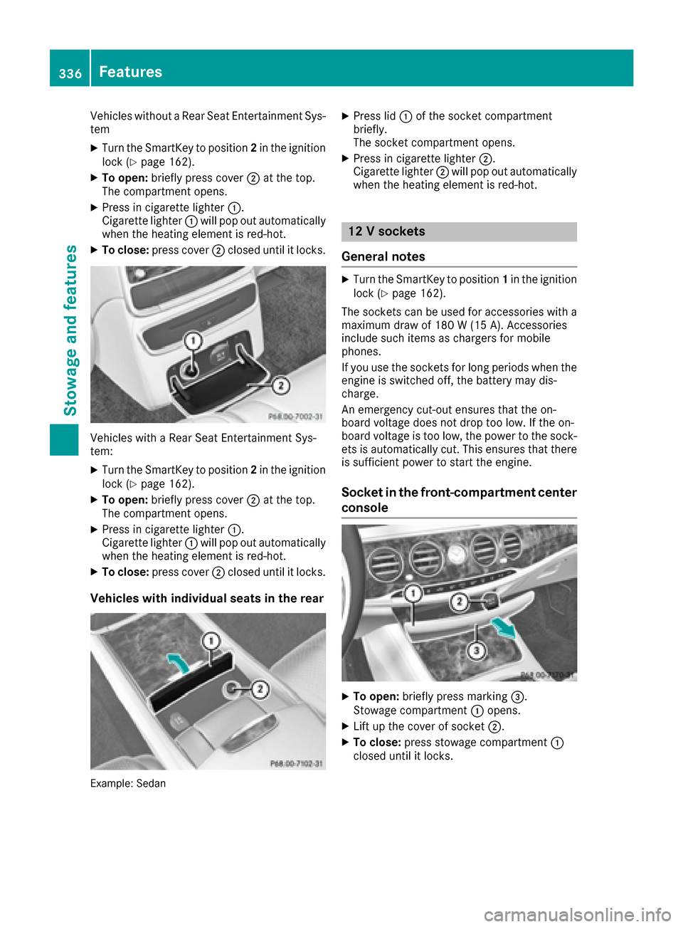
Vehicles without a Rear Seat Entertainment Sys-
tem
XTurn the SmartKey to position2in the ignition
lock (Ypage 162).
XTo open: briefly press cover ;at the top.
The compartment opens.
XPress in cigarette lighter :.
Cigarette lighter :will pop out automatically
when the heating element is red-hot.
XTo close: press cover ;closed until it locks.
Vehicles with a Rear Seat Entertainment Sys-
tem:
XTurn the SmartKey to position 2in the ignition
lock (Ypage 162).
XTo open: briefly press cover ;at the top.
The compartment opens.
XPress in cigarette lighter :.
Cigarette lighter :will pop out automatically
when the heating element is red-hot.
XTo close: press cover ;closed until it locks.
Vehicles with individual seats in the rear
Example: Sedan
XPress lid :of the socket compartment
briefly.
The socket compartment opens.
XPress in cigarette lighter ;.
Cigarette lighter ;will pop out automatically
when the heating element is red-hot.
12 V sockets
General notes
XTurn the SmartKey to position 1in the ignition
lock (Ypage 162).
The sockets can be used for accessories with a maximum draw of 180 W (15 A). Accessories
include such items as chargers for mobile
phones.
If you use the sockets for long periods when the
engine is switched off, the battery may dis-
charge.
An emergency cut-out ensures that the on-
board voltage does not drop too low. If the on-
board voltage is too low, the power to the sock-
ets is automatically cut. This ensures that there is sufficient power to start the engine.
Socket in the front-compartment center
console
XTo open: briefly press marking =.
Stowage compartment :opens.
XLift up the cover of socket ;.
XTo close:press stowage compartment :
closed until it locks.
336Features
Stowage and features
Page 339 of 438
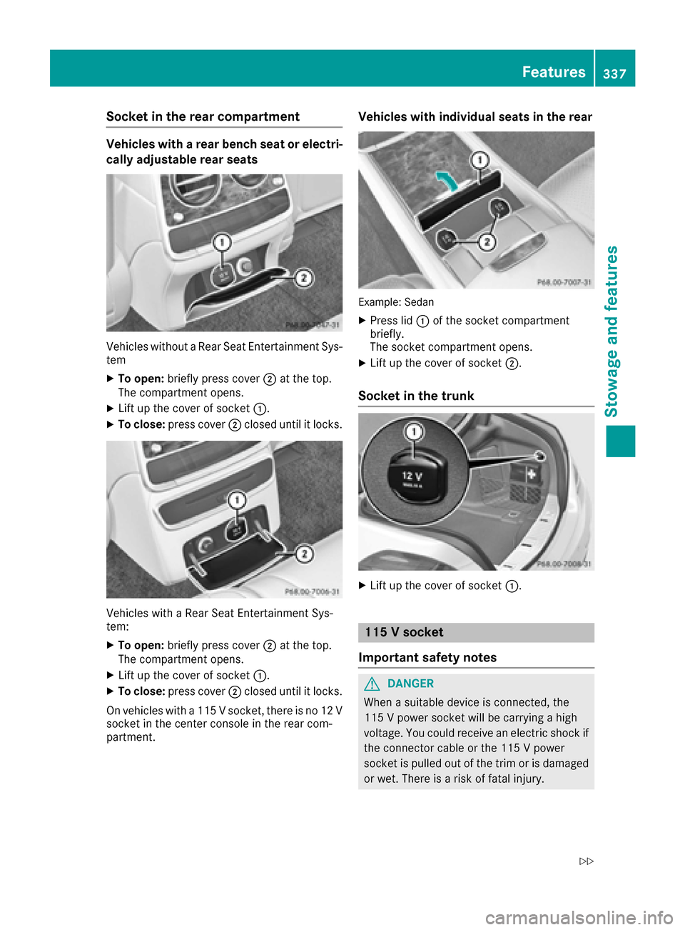
Socket in the rear compartment
Vehicles with a rear bench seat or electri-
cally adjustable rear seats
Vehicles without a Rear Seat Entertainment Sys-
tem
XTo open:briefly press cover ;at the top.
The compartment opens.
XLift up the cover of socket :.
XTo close:press cover ;closed until it locks.
Vehicles with a Rear Seat Entertainment Sys-
tem:
XTo open: briefly press cover ;at the top.
The compartment opens.
XLift up the cover of socket :.
XTo close:press cover ;closed until it locks.
On vehicles with a 115 V socket, there is no 12 V
socket in the center console in the rear com-
partment.
Vehicles with individual seats in the rear
Example: Sedan
XPress lid :of the socket compartment
briefly.
The socket compartment opens.
XLift up the cover of socket ;.
Socket in the trunk
XLift up the cover of socket:.
115 V socket
Important safety notes
GDANGER
When a suitable device is connected, the
115 V power socket will be carrying a high
voltage. You could receive an electric shock if the connector cable or the 115 V power
socket is pulled out of the trim or is damaged
or wet. There is a risk of fatal injury.
Features337
Stowage and features
Z
Page 340 of 438
RUse only connector cables that are dry and
free of damage.
RWhen the ignition is off, make sure that the
115 V power socket is dry.
RHave the 115 V power socket checked or
replaced immediately at a qualified speci-
alized workshop if it is damaged or has been
pulled out of the trim.
RNever plug the connector cable into a 115 V
power socket that is damaged or has been
pulled out of the trim.
GDANGER
If you reach into the power socket or plug
inappropriate devices into the power socket,
you could receive an electric shock. There is a
risk of fatal injury.
Only connect appropriate devices to the
power socket.
!Note that work and repairs on the 115 V
power socket should only be carried out by
qualified specialist personnel.
General notes
The 115 V power socket provides an alternating
voltage of 115 V so that small electronic devices
can be connected. These devices, such as
games consoles, chargers and laptops, must not consume more than a maximum of 150 watts
altogether.
Requirements for operation of these devices:
Rthe electronic device that you connect has a
suitable connector and conforms to stand-
ards specific to the country you are in.
Rthe plug of the electronic device is plugged
correctly into 115 V power socket.
Rthe maximum wattage of the device to be
connected must not exceed 150 watts.
Rthe on-board power supply is within a permis-sible voltage range.
Rthe 12 V sockets in the center console in the
front compartment (Ypage 336) and in the
trunk are functional (Ypage 337).
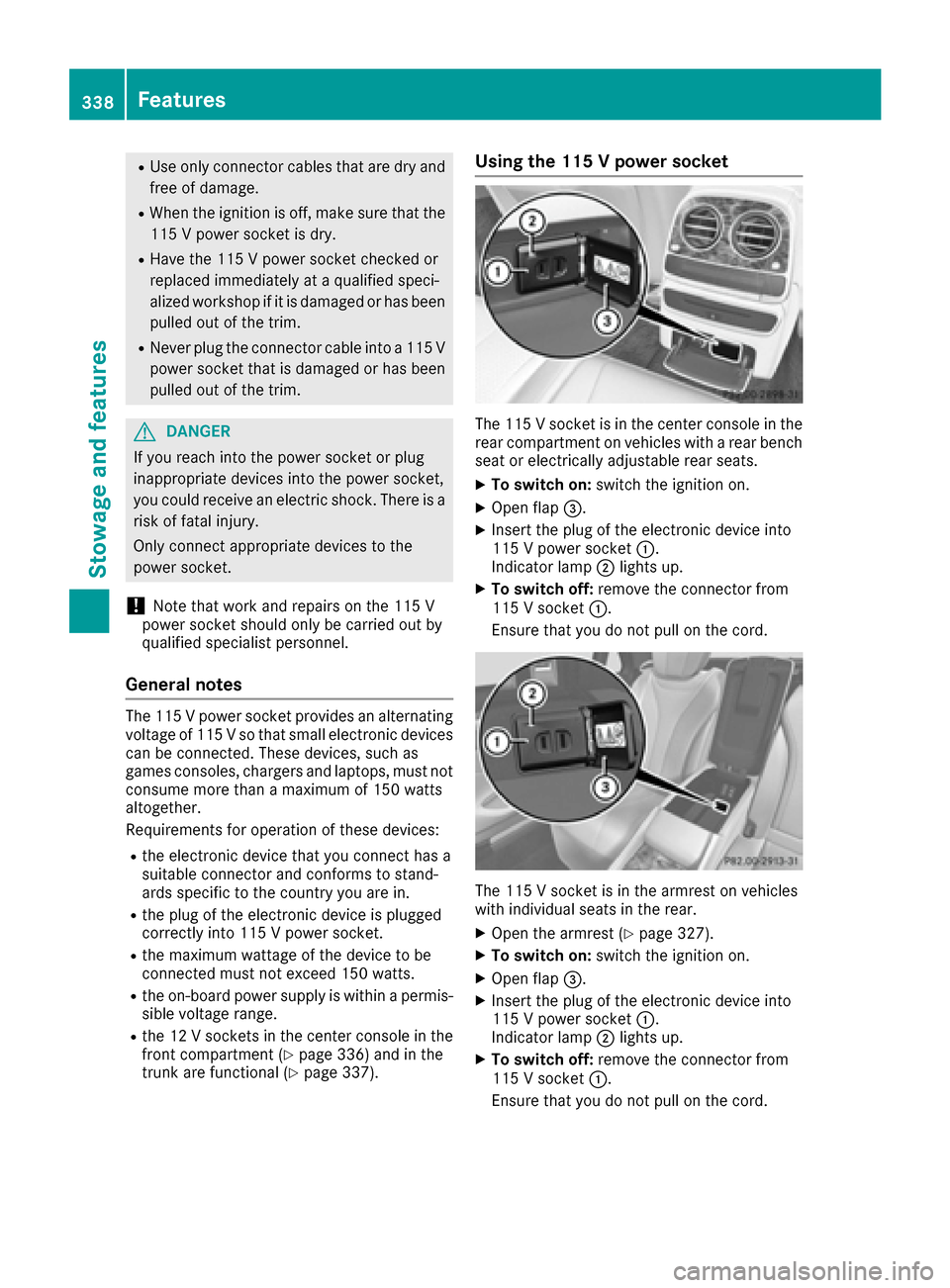
Using the 115 V power socket
The 115 V socket is in the center console in the
rear compartment on vehicles with a rear bench
seat or electrically adjustable rear seats.
XTo switch on: switch the ignition on.
XOpen flap=.
XInsert the plug of the electronic device into
115 V power socket :.
Indicator lamp ;lights up.
XTo switch off: remove the connector from
115 V socket :.
Ensure that you do not pull on the cord.
The 115 V socket is in the armrest on vehicles
with individual seats in the rear.
XOpen the armrest (Ypage 327).
XTo switch on: switch the ignition on.
XOpen flap=.
XInsert the plug of the electronic device into
115 V power socket :.
Indicator lamp ;lights up.
XTo switch off: remove the connector from
115 V socket :.
Ensure that you do not pull on the cord.
338Features
Stowage and features
Page 352 of 438
operate in the frequency range of 280 to
433 MHz.
RReplace the batteries in garage door remote
controlA. This increases the likelihood that
garage door remote control Awill transmit a
strong and precise signal to the integrated
garage door opener.
RWhen programming, hold remote control A
at varying distances and angles from the but-
ton which you are programming. Try various
angles at a distance between 2and 12 inches
(5to 30 cm) or at the same angle but at varying
distances.
RIf another remote control is available for the
same garage door drive, repeat the same pro-
gramming steps with this remote control.
Before performing these steps, make sure
that new batteries have been installed in
garage door drive remote control A.
RNote that some remote controls only transmit
for a limited amount of time (the indicator
lamp on the remote control goes out). Press
buttonBon remote control Aagain before
transmission ends.
RAlign the antenna cable of the garage door
opener unit. This can improve signal recep-
tion/transmission.
Opening/closing the garage door
After it has been programmed, the integrated
garage door opener performs the function of the
garage door system remote control. Please also
read the operating instructions for the garage
door system.
XTurn the SmartKey to position 2in the ignition
lock (Ypage 162).
XPress button ;,=or? which you have
programmed to operate the garage door.
Garage door system with a fixed code: indi-
cator lamp :lights up green.
Garage door system with a rolling code: indi-
cator lamp :flashes green.
The transmitter will transmit a signal as long
as the button is pressed. The transmission is
halted after a maximum of ten seconds and
indicator lamp :lights up yellow.
XPress button ;,=or? again if necessary.
Clearing the memory
Make sure that you clear the memory of the
integrated garage door opener before selling the
vehicle.
XTurn the SmartKey to position 2in the ignition
lock (Ypage 162).
XPress and hold buttons ;and ?.
The indicator lamp initially lights up yellow
and then green.
XRelease buttons ;and ?.
The memory of the integrated garage door
opener in the rear-view mirror is cleared.
Floormats
GWARNING
Objects in the driver's footwell can restrict the pedal travel or obstruct a depressed pedal.
The operating and road safety of the vehicle is
jeopardized. There is a risk of an accident.
Make sure that all objects in the vehicle are
stowed correctly, and that they cannot enter
the driver's footwell. Install the floormats
securely and as specified in order to ensure
sufficient clearance for the pedals. Do not use
loose floormats and do not place floormats on
top of one another.
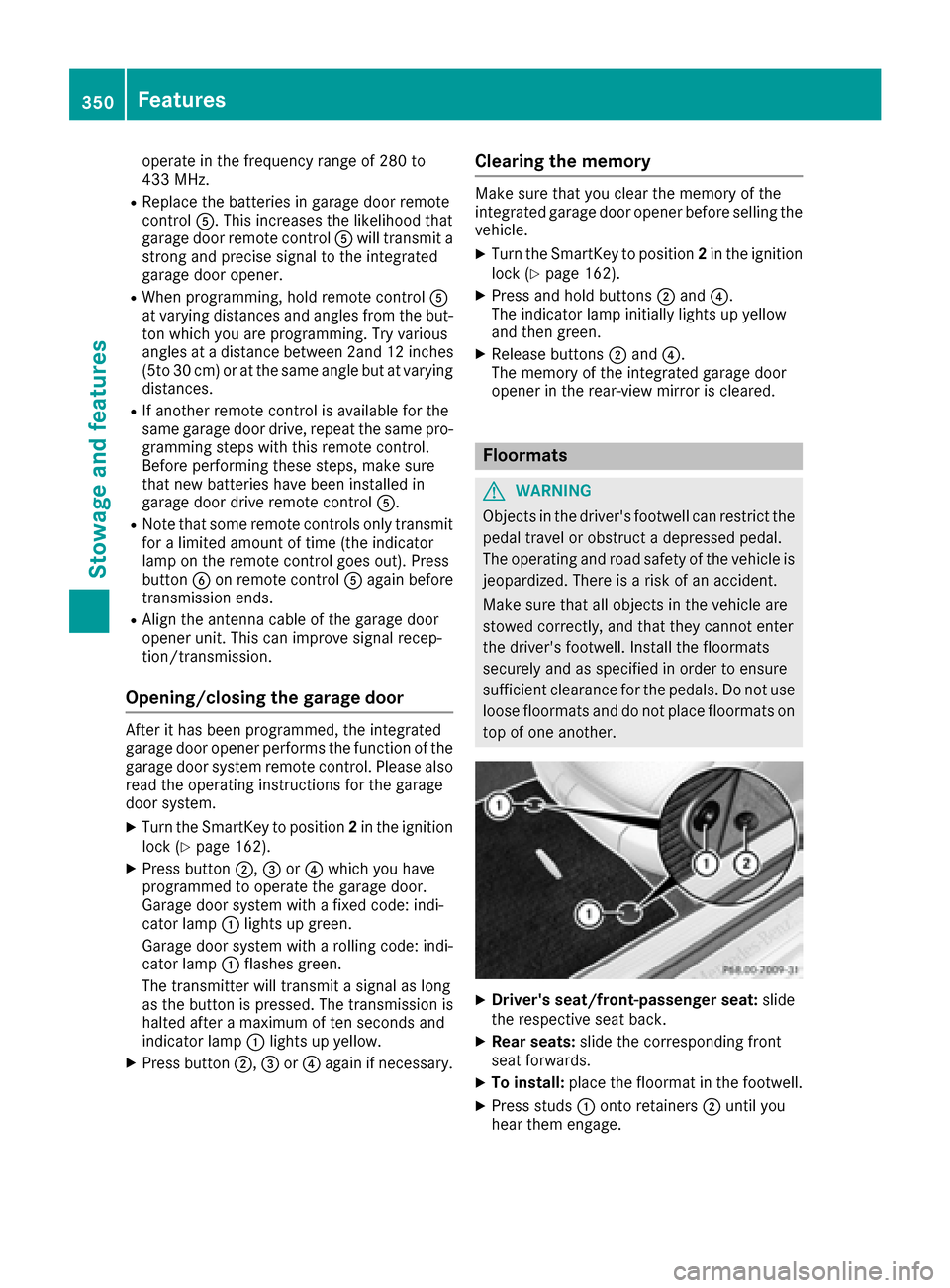
XDriver's seat/front-passenger seat: slide
the respective seat back.
XRear seats: slide the corresponding front
seat forwards.
XTo install: place the floormat in the footwell.
XPress studs :onto retainers ;until you
hear them engage.
350Features
Stowage and features
Page 374 of 438
Battery (vehicle)
12 V battery – important safety notes
PLUG-IN HYBRID vehicles are equipped with a
12 V battery and a high-voltage battery. The fol-
lowing notes refer to the 12 V battery. Notes on
the high-voltage battery can be obtained in the
"High-voltage battery – important safety notes"
section (
Ypage 374).
Special tools and expert knowledge are required
when working on the battery, e.g. removal and
installation. You should therefore have all work
involving the battery carried out at a qualified
specialist workshop.
GWARNING
Work carried out incorrectly on the battery
can lead, for example, to a short circuit and
thus damage the vehicle electronics. This can
lead to function restrictions applying to
safety-relevant systems, e.g the lighting sys-
tem, the ABS (anti-lock braking system) or the
ESP
®(Electronic Stability Program). The oper-
ating safety of your vehicle may be restricted.
You could lose control of the vehicle, for
example:
Rwhen braking
Rin the event of abrupt steering maneuvers
and/or when the vehicle's speed is not
adapted to the road conditions
There is a risk of an accident.
In the event of a short circuit or a similar inci-
dent, contact a qualified specialist workshop
immediately. Do not drive any further. You
should have all work involving the battery car- ried out at a qualified specialist workshop.
For further information about ABS and ESP
®,
see (Ypage 68) and (Ypage 73).
All vehicles except Mercedes-AMG vehicles:
GWARNING
Electrostatic build-up can lead to the creation of sparks, which could ignite the highly explo-
sive gases of a battery. There is a risk of an
explosion.
Before handling the battery, touch the vehicle
body to remove any existing electrostatic
build-up.
The highly flammable gas mixture forms when
charging the battery as well as when jump-start-
ing.
Always make sure that neither you nor the bat-
tery is electrostatically charged. A build-up of
electrostatic charge can be caused, for exam-
ple:
Rby wearing clothing made from synthetic
fibers
Rdue to friction between clothing and seats
Rif you push or pull the battery across the car-
pet or other synthetic materials
Rif you wipe the battery with a cloth
GWARNING
During the charging process, a battery produ-
ces hydrogen gas. If a short circuit occurs or
sparks are created, the hydrogen gas can
ignite. There is a risk of an explosion.
RMake sure that the positive terminal of a
connected battery does not come into con- tact with vehicle parts.
RNever place metal objects or tools on a bat-
tery.
RIt is important that you observe the descri-
bed order of the battery terminals when
connecting and disconnecting a battery.
RWhen jump-starting, make sure that the
battery poles with identical polarity are
connected.
RIt is particularly important to observe the
described order when connecting and dis-
connecting the jumper cables.
RNever connect or disconnect the battery
terminals while the engine is running.
GWARNING
Battery acid is caustic. There is a risk of injury.
Avoid contact with skin, eyes or clothing. Do
not inhale any battery gases. Do not lean over
the battery. Keep children away from batter-
ies. Wash away battery acid immediately with
372Battery (vehicle)
Breakdo wn assis tance
Page 390 of 438
Tire and Loading Information placard
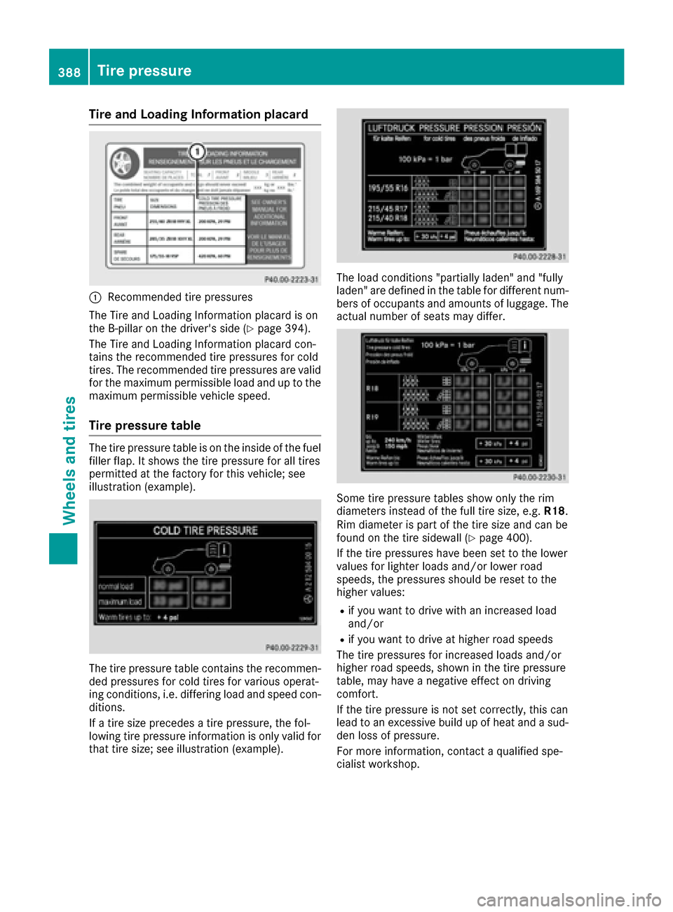
:Recommended tire pressures
The Tire and Loading Information placard is on
the B-pillar on the driver's side (
Ypage 394).
The Tire and Loading Information placard con-
tains the recommended tire pressures for cold
tires. The recommended tire pressures are valid
for the maximum permissible load and up to the
maximum permissible vehicle speed.
Tire pressure table
The tire pressure table is on the inside of the fuel
filler flap. It shows the tire pressure for all tires
permitted at the factory for this vehicle; see
illustration (example).
The tire pressure table contains the recommen-
ded pressures for cold tires for various operat-
ing conditions, i.e. differing load and speed con-
ditions.
If a tire size precedes a tire pressure, the fol-
lowing tire pressure information is only valid for that tire size; see illustration (example).
The load conditions "partially laden" and "fully
laden" are defined in the table for different num-
bers of occupants and amounts of luggage. The
actual number of seats may differ.
Some tire pressure tables show only the rim
diameters instead of the full tire size, e.g. R18.
Rim diameter is part of the tire size and can be
found on the tire sidewall (
Ypage 400).
If the tire pressures have been set to the lower
values for lighter loads and/or lower road
speeds, the pressures should be reset to the
higher values:
Rif you want to drive with an increased load
and/or
Rif you want to drive at higher road speeds
The tire pressures for increased loads and/or
higher road speeds, shown in the tire pressure
table, may have a negative effect on driving
comfort.
If the tire pressure is not set correctly, this can
lead to an excessive build up of heat and a sud-
den loss of pressure.
For more information, contact a qualified spe-
cialist workshop.
388Tire pressure
Wheels and tires
Page 397 of 438
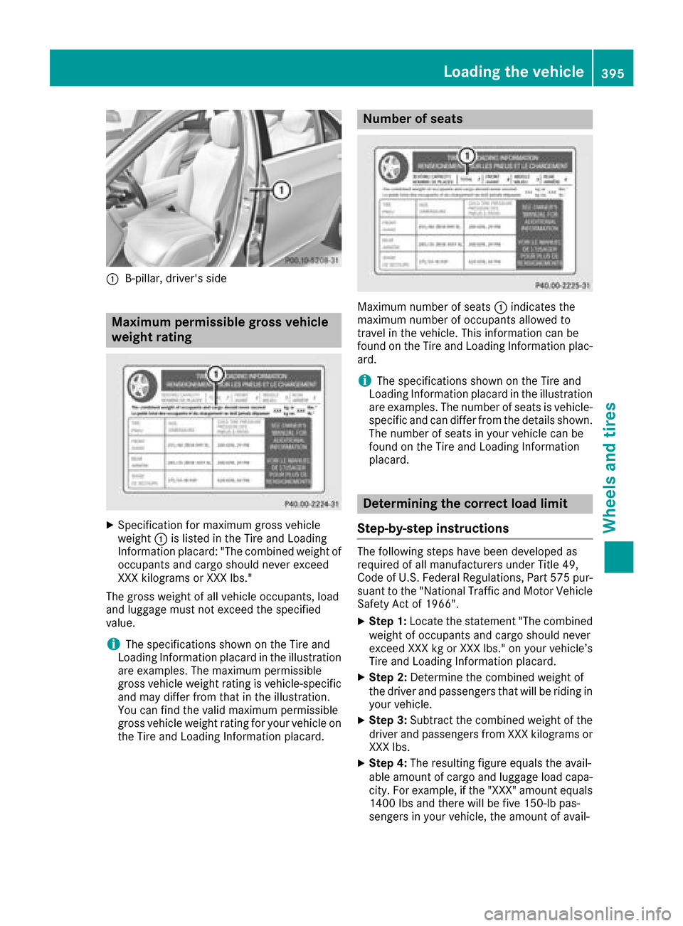
:B-pillar, driver's side
Maximum permissible gross vehicle
weight rating
XSpecification for maximum gross vehicle
weight:is listed in the Tire and Loading
Information placard: "The combined weight of occupants and cargo should never exceed
XXX kilograms or XXX lbs."
The gross weight of all vehicle occupants, load
and luggage must not exceed the specified
value.
iThe specifications shown on the Tire and
Loading Information placard in the illustration are examples. The maximum permissible
gross vehicle weight rating is vehicle-specific
and may differ from that in the illustration.
You can find the valid maximum permissible
gross vehicle weight rating for your vehicle on
the Tire and Loading Information placard.
Number of seats
Maximum number of seats :indicates the
maximum number of occupants allowed to
travel in the vehicle. This information can be
found on the Tire and Loading Information plac-
ard.
iThe specifications shown on the Tire and
Loading Information placard in the illustration
are examples. The number of seats is vehicle-
specific and can differ from the details shown.
The number of seats in your vehicle can be
found on the Tire and Loading Information
placard.
Determining the correct load limit
Step-by-step instructions
The following steps have been developed as
required of all manufacturers under Title 49,
Code of U.S. Federal Regulations, Part 575 pur-
suant to the "National Traffic and Motor Vehicle
Safety Act of 1966".
XStep 1: Locate the statement "The combined
weight of occupants and cargo should never
exceed XXX kg or XXX lbs." on your vehicle’s
Tire and Loading Information placard.
XStep 2: Determine the combined weight of
the driver and passengers that will be riding in your vehicle.
XStep 3: Subtract the combined weight of the
driver and passengers from XXX kilograms or
XXX lbs.
XStep 4: The resulting figure equals the avail-
able amount of cargo and luggage load capa-
city. For example, if the "XXX" amount equals
1400 lbs and there will be five 150-lb pas-
sengers in your vehicle, the amount of avail-
Loading the vehicle395
Wheels and tires
Z
Page 407 of 438
Load bearing index
The load bearing index (also load index) is a code
that contains the maximum load bearing capa-
city of a tire.
Traction
Traction is the result of friction between the tires
and the road surface.
Treadwear indicators
Narrow bars (tread wear bars) that are distrib-
uted over the tire tread. If the tire tread is level
with the bars, the wear limit ofáin (1.6 mm)
has been reached.
Occupant distribution
The distribution of occupants in a vehicle at their
designated seating positions.
Total load limit
Nominal load and luggage load plus 68 kg
(15 0lbs) multiplied by the number of seats in
the vehicle.
Changing a wheel
Flat tire
The "Breakdown assistance" section
(Ypage 367) contains information and notes on
how to deal with a flat tire. Information on driv-
ing with MOExtended tires in the event of a flat
tire can be found under "MOExtended tires (tires
with run-flat characteristics" (
Ypage 368).
Rotating the wheels
GWARNING
Interchanging the front and rear wheels may
severely impair the driving characteristics if
the wheels or tires have different dimensions. The wheel brakes or suspension components
may also be damaged. There is a risk of acci-
dent.
Rotate front and rear wheels only if the wheels and tires are of the same dimensions.
!On vehicles equipped with a tire pressure
monitor, electronic components are located
in the wheel. Tire-mounting tools should not be used near
the valve. This could damage the electronic
components.
Only have tires changed at a qualified spe-
cialist workshop.
Always observe the instructions and safety
notes in the "Mounting a wheel" section
(
Ypage 406).
The wear patterns on the front and rear tires
differ, depending on the operating conditions.
Rotate the wheels before a clear wear pattern
has formed on the tires. Front tires typically
wear more on the shoulders and the rear tires in
the center.
On vehicles that have the same size front and
rear wheels, you can rotate the wheels accord-
ing to the intervals in the tire manufacturer's
warranty book in your vehicle documents. If no
warranty book is available, the tires should be
rotate every 3,000 to 6,000 miles (5,000 to
10,000 km). Earlier may be necessary, depend-
ing on the degree of tire wear. Do not change the
direction of wheel rotation.
Clean the contact surfaces of the wheel and the
brake disc thoroughly every time a wheel is rota-
ted. Check the tire pressure and, if necessary,
restart the tire pressure loss warning system
(
Ypage 394) or the tire pressure monitor
(Ypage 392).
Direction of rotation
Tires with a specified direction of rotation have
additional benefits, e.g. if there is a risk of hydro- planing. These advantages can only be gained if
the tires are installed corresponding to the
direction of rotation.
An arrow on the sidewall of the tire indicates its
correct direction of rotation.
Storing wheels
Store wheels that are not being used in a cool,
dry and preferably dark place. Protect the tires
from oil, grease, gasoline and diesel.
Changing a wheel405
Wheels and tires
Z