2016 MERCEDES-BENZ S-Class SEDAN REAR BRAKE
[x] Cancel search: REAR BRAKEPage 379 of 438

Do not start the vehicle using a rapid charging device. If your vehicle's battery is discharged, the
engine can be jump-started from another vehicle or from a second battery using jumper cables.
Observe the following points:
RThe battery is not accessible in all vehicles. If the other vehicle's battery is not accessible, jump-
start the vehicle using a second battery or a jump-starting device.
RYou may only jump-start the vehicle when the engine and exhaust system are cold.
RAll vehicles except Mercedes-AMG vehicles: do not start the engine if the battery is frozen. Let
the battery thaw first.
ROnly jump-start from batteries with a 12 V voltage rating.
ROnly use jumper cables which have a sufficient cross-section and insulated terminal clamps.
RIf the battery is fully discharged, leave the battery that is being used to jump-start connected for
a few minutes before attempting to start. This charges the battery slightly.
RMake sure that the two vehicles do not touch.
Make sure that:
Rthe jumper cables are not damaged.
Rwhen the jumper cables are connected to the battery, uninsulated sections of the terminal clamp
do not come into contact with other metal sections.
Rthe jumper cables cannot come into contact with parts which can move when the engine is
running, such as the V-belt pulley or the fan.
XSecure the vehicle by applying the electric parking brake.
XShift the transmission to position P.
XMake sure that the ignition is switched off. All indicator lamps in the instrument cluster must be
off. When using the SmartKey, turn the SmartKey to position 0in the ignition lock and remove it
(
Ypage 162).
XSwitch off all electrical consumers, e.g. rear window defroster, lighting, etc.
XOpen the hood.
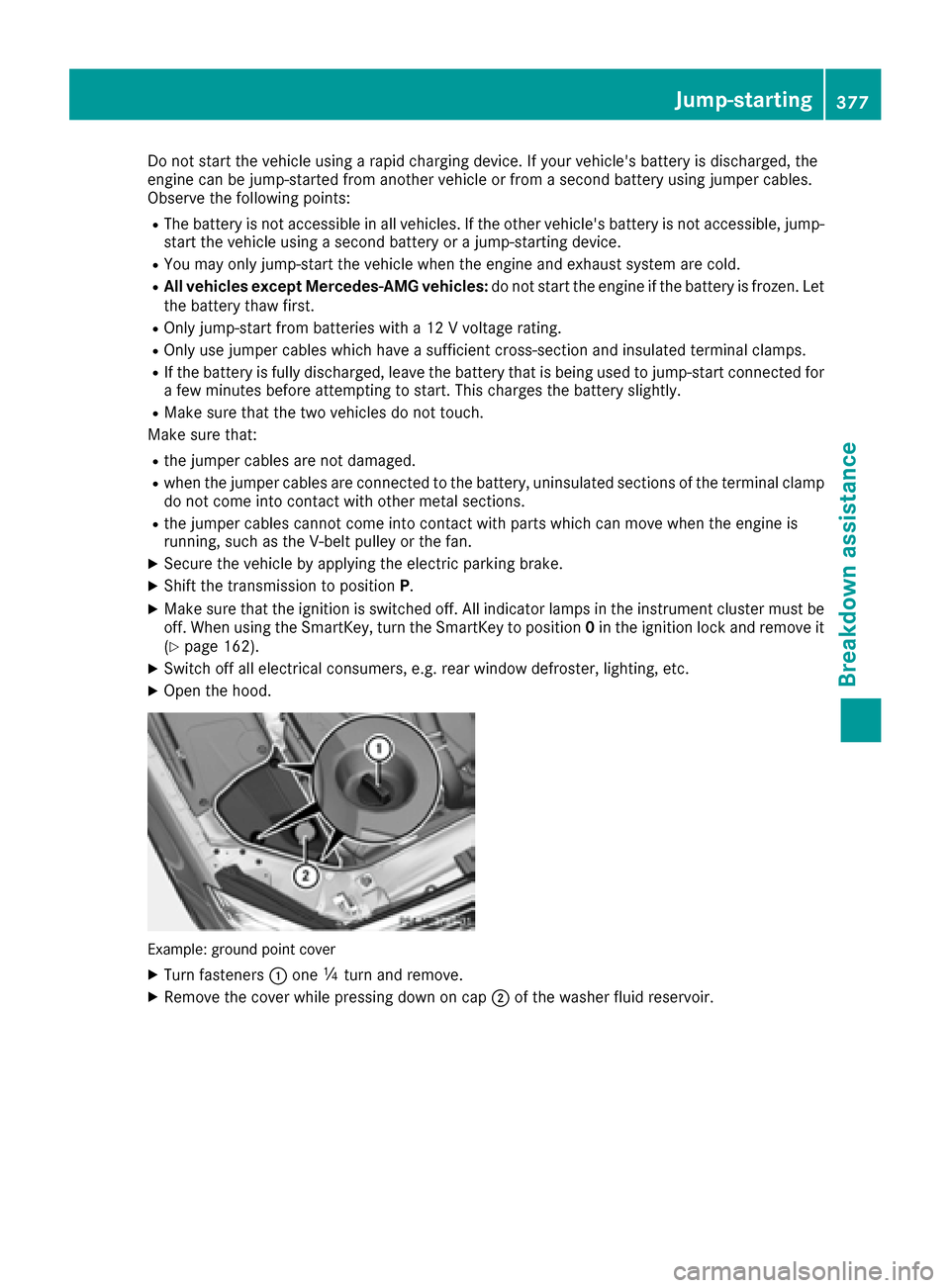
Example: ground point cover
XTurn fasteners :one Õturn and remove.
XRemove the cover while pressing down on cap ;of the washer fluid reservoir.
Jump-starting377
Breakdown assistance
Z
Page 382 of 438

PLUG-IN HYBRID vehicles may not be towed
away but must instead be transported, if:
Rthe multifunction display is not working or
Rtheá Towing Not Permitted SeeOperator'sManualmessage appears in the
multifunction display.
If the vehicle is in a dangerous area, it can be
towed out of that area with both axles on the
ground. In this case, the towing distance must
not be greater than 165 ft (50 m)and must not
exceed a towing speed of 6 mph (10 km/h). For
longer distances, have the vehicle loaded and
transported.
Installing/removing the towing eye
Installing the towing eye
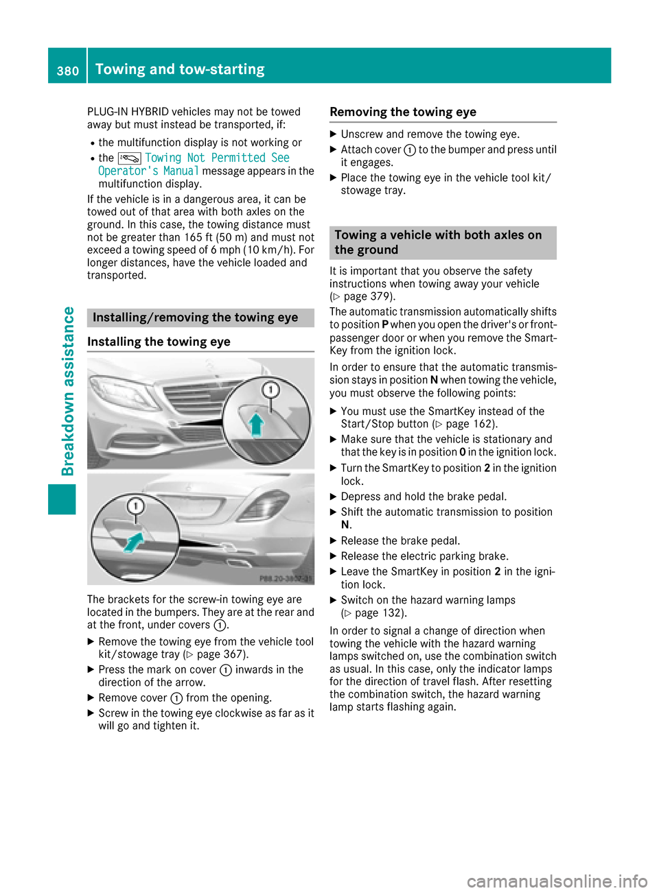
The brackets for the screw-in towing eye are
located in the bumpers. They are at the rear and
at the front, under covers :.
XRemove the towing eye from the vehicle tool
kit/stowage tray (Ypage 367).
XPress the mark on cover:inwards in the
direction of the arrow.
XRemove cover :from the opening.
XScrew in the towing eye clockwise as far as it
will go and tighten it.
Removing the towing eye
XUnscrew and remove the towing eye.
XAttach cover :to the bumper and press until
it engages.
XPlace the towing eye in the vehicle tool kit/
stowage tray.
Towing a vehicle with both axles on
the ground
It is important that you observe the safety
instructions when towing away your vehicle
(
Ypage 379).
The automatic transmission automatically shifts
to position Pwhen you open the driver's or front-
passenger door or when you remove the Smart-
Key from the ignition lock.
In order to ensure that the automatic transmis-
sion stays in position Nwhen towing the vehicle,
you must observe the following points:
XYou must use the SmartKey instead of the
Start/Stop button (Ypage 162).
XMake sure that the vehicle is stationary and
that the key is in position 0in the ignition lock.
XTurn the SmartKey to position 2in the ignition
lock.
XDepress and hold the brake pedal.
XShift the automatic transmission to position
N .
XRelease the brake pedal.
XRelease the electric parking brake.
XLeave the SmartKey in position 2in the igni-
tion lock.
XSwitch on the hazard warning lamps
(Ypage 132).
In order to signal a change of direction when
towing the vehicle with the hazard warning
lamps switched on, use the combination switch
as usual. In this case, only the indicator lamps
for the direction of travel flash. After resetting
the combination switch, the hazard warning
lamp starts f
lashing again.
380Towing and tow-starting
Breakdown assistance
Page 383 of 438

Transporting the vehicle
PLUG-IN HYBRID vehicles
Transportation of the vehicle should only be car-
ried out by professional recovery companies.
4MATIC vehicles/vehicles with auto-
matic transmission
!When the vehicle is loaded for transport, the
front and rear axles must be stationary and on
the same transportation vehicle. Positioning
over the connection point of the transport
vehicle is not permitted. The drive train may
otherwise be damaged.
All vehicles
!You may only secure the vehicle by the
wheels, not by parts of the vehicle such as
axle or steering components. Otherwise, the
vehicle could be damaged.
The towing eye can be used to pull the vehicle
onto a trailer or transporter for transporting pur-
poses.
XTurn the SmartKey to position 2in the ignition
lock.
XShift the automatic transmission to position
N.
As soon as the vehicle has been loaded:
XPrevent the vehicle from rolling away by
applying the electric parking brake.
XShift the automatic transmission to posi-
tion P.
XTurn the SmartKey to position 0in the ignition
lock and remove it.
XSecure the vehicle.
Notes on 4MATIC vehicles
!
Vehicles with 4MATIC must not be towed
with either the front or the rear axle raised, as
doing so will damage the transmission.
Vehicles with 4MATIC may either be towed away with both axles on the ground or be loaded up
and transported.
If the vehicle's transmission, front, or rear axle is
damaged, have the vehicle transported on a
truck or trailer.
In the event of damage to the electrical sys-
tem: if the battery is defective, the automatic
transmission will be locked in position P. To shift
the automatic transmission to position N, you
must provide power to the vehicle's electrical
system in the same way as when jump-starting
(
Ypage 376).
Have the vehicle transported on a transporter or
trailer.
Tow-starting (emergency engine
starting)
!
Vehicles with automatic transmission must
not be tow-started. You could otherwise dam-
age the automatic transmission.
iInformation on "Jump-starting"
(Ypage 376).
Fuses
Important safety notes
GWARNING
If you manipulate or bridge a faulty fuse or if
you replace it with a fuse with a higher amper- age, the electric cables could be overloaded.
This could result in a fire. There is a risk of an
accident and injury.
Always replace faulty fuses with the specified
new fuses having the correct amperage.
Blown fuses must be replaced with fuses of the
same rating, which you can recognize by the
color and value. The fuse ratings are listed in the
fuse allocation chart.
The fuse allocation chart is on the fuse box in the
trunk (
Ypage 381).
Fuses381
Breakdown assistance
Z
Page 396 of 438

Restarting the tire pressure loss warn-
ing system
Restart the tire pressure loss warning system if
you have:
Rchanged the tire pressure
Rchanged the wheels or tires
Rmounted new wheels or tires
XBefore restarting, make sure that the tire
pressures are set properly on all four tires for
the respective operating conditions.
The recommended tire pressure can be foundon the Tire and Loading Information placard
on the B-pillar on the driver's side. Addition-
ally, a tire pressure table is attached to the
fuel filler flap. The tire pressure loss warning
system can only give reliable warnings if you
have set the correct tire pressure. If an incor-
rect tire pressure is set, these incorrect val-
ues will be monitored.
XAlso observe the notes in the section on tire
pressures (Ypage 387).
XMake sure that the SmartKey is in position 2
in the ignition lock (Ypage 162).
XUse ò on the steering wheel to call up the
list of menus.
XPress 9or: on the steering wheel to
select the Servicemenu.
XPress theabutton.
XPress 9or: to select Tire Pres‐sure.
XPress the abutton.
The Run Flat Indicator ActivePress
'OK' to Restartmessage appears in the
multifunction display.
If you wish to confirm the restart:
XPress the abutton.
The Tire Pressure Now OK?message
appears in the multifunction display.
XPress 9or: to select Yes.
XPress the abutton.
The Run Flat Indicator Restartedmes-
sage appears in the multifunction display.
After a teach-in period, the tire pressure loss
warning system will monitor the set tire pres- sures of all four tires. If you wish to cancel the restart:
XPress the
%button.
or
XIf the Tire Pressure Now OK?message
appears, select Cancelby pressing9
or :.
XPress the abutton.
The tire pressure values stored at the last
restart will continue to be monitored.
Loading the vehicle
Instruction labels for tires and loads
GWARNING
Overloaded tires can overheat, causing a
blowout. Overloaded tires can also impair the steering and driving characteristics and lead
to brake failure. There is a risk of accident.
Observe the load rating of the tires. The load
rating must be at least half of the GAWR of
your vehicle. Never overload the tires by
exceeding the maximum load.
Two instruction labels on your vehicle show the maximum possible load.
(1) The Tire and Loading Information placard is on the B-pillar on the driver's side. The Tire
and Loading Information placard shows the
maximum permissible number of occu-
pants and the maximum permissible vehicle
load. It also contains details of the tire sizes
and corresponding pressures for tires
mounted at the factory.
(2) The vehicle identification plate is on the B- pillar on the driver's side. The vehicle iden-
tification plate informs you of the gross
vehicle weight rating. It is made up of the
vehicle weight, all vehicle occupants, the
fuel and the cargo. You can also find infor-
mation about the maximum gross axle
weight rating on the front and rear axle.
The maximum gross axle weight rating is
the maximum weight that can be carried by
one axle (front or rear axle). Never exceed
the maximum load or the maxi mum g
ross
axle weight rating for the front or rear axle.
394Loading the vehicle
Wheels and tires
Page 407 of 438

Load bearing index
The load bearing index (also load index) is a code
that contains the maximum load bearing capa-
city of a tire.
Traction
Traction is the result of friction between the tires
and the road surface.
Treadwear indicators
Narrow bars (tread wear bars) that are distrib-
uted over the tire tread. If the tire tread is level
with the bars, the wear limit ofáin (1.6 mm)
has been reached.
Occupant distribution
The distribution of occupants in a vehicle at their
designated seating positions.
Total load limit
Nominal load and luggage load plus 68 kg
(15 0lbs) multiplied by the number of seats in
the vehicle.
Changing a wheel
Flat tire
The "Breakdown assistance" section
(Ypage 367) contains information and notes on
how to deal with a flat tire. Information on driv-
ing with MOExtended tires in the event of a flat
tire can be found under "MOExtended tires (tires
with run-flat characteristics" (
Ypage 368).
Rotating the wheels
GWARNING
Interchanging the front and rear wheels may
severely impair the driving characteristics if
the wheels or tires have different dimensions. The wheel brakes or suspension components
may also be damaged. There is a risk of acci-
dent.
Rotate front and rear wheels only if the wheels and tires are of the same dimensions.
!On vehicles equipped with a tire pressure
monitor, electronic components are located
in the wheel. Tire-mounting tools should not be used near
the valve. This could damage the electronic
components.
Only have tires changed at a qualified spe-
cialist workshop.
Always observe the instructions and safety
notes in the "Mounting a wheel" section
(
Ypage 406).
The wear patterns on the front and rear tires
differ, depending on the operating conditions.
Rotate the wheels before a clear wear pattern
has formed on the tires. Front tires typically
wear more on the shoulders and the rear tires in
the center.
On vehicles that have the same size front and
rear wheels, you can rotate the wheels accord-
ing to the intervals in the tire manufacturer's
warranty book in your vehicle documents. If no
warranty book is available, the tires should be
rotate every 3,000 to 6,000 miles (5,000 to
10,000 km). Earlier may be necessary, depend-
ing on the degree of tire wear. Do not change the
direction of wheel rotation.
Clean the contact surfaces of the wheel and the
brake disc thoroughly every time a wheel is rota-
ted. Check the tire pressure and, if necessary,
restart the tire pressure loss warning system
(
Ypage 394) or the tire pressure monitor
(Ypage 392).
Direction of rotation
Tires with a specified direction of rotation have
additional benefits, e.g. if there is a risk of hydro- planing. These advantages can only be gained if
the tires are installed corresponding to the
direction of rotation.
An arrow on the sidewall of the tire indicates its
correct direction of rotation.
Storing wheels
Store wheels that are not being used in a cool,
dry and preferably dark place. Protect the tires
from oil, grease, gasoline and diesel.
Changing a wheel405
Wheels and tires
Z
Page 408 of 438

Mounting a wheel
Preparing the vehicle
XStop the vehicle on solid, non-slippery and
level ground.
XApply the electric parking brake manually.
XBring the front wheels into the straight-ahead position.
XShift the transmission to position P.
XMake sure that "normal" level is selected for
AIRMATIC (Ypage 212) or Active Body Con-
trol (ABC) (Ypage 210).
XSwitch off the engine.
XOpen the driver's door.
The on-board electronics now have status 0.
This is the same as the SmartKey having been
removed.
XRemove Start/Stop button from ignition lock (Ypage 162).
or, if the SmartKey is inserted in the ignition
lock:
XRemove the SmartKey from the ignition lock.
XMake sure that the engine cannot be started
via your smartphone (Ypage 164).
XIf included in the vehicle equipment, remove
the tire-change tool kit from the vehicle.
XSafeguard the vehicle against rolling away.
Securing the vehicle to prevent it from
rolling away
If your vehicle is equipped with a wheel chock, it can be found in the tire-change tool kit
(
Ypage 367).
The folding wheel chock is an additional safety
measure to prevent the vehicle from rolling
away, for example when changing a wheel.
XFold both plates upwards :.
XFold out lower plate;.
XGuide the lugs on the lower plate fully into the
openings in base plate =.
XPlace chocks or other suitable items under
the front and rear of the wheel that is diago-
nally opposite the wheel you wish to change.
Raising the vehicle
GWARNING
If you do not position the jack correctly at the
appropriate jacking point of the vehicle, the
jack could tip over with the vehicle raised.
There is a risk of injury.
Only position the jack at the appropriate jack-
ing point of the vehicle. The base of the jack
must be positioned vertically, directly under
the jacking point of the vehicle.
!The jack is designed exclusively for jacking
up the vehicle at the jacking points. Other-
wise, your vehicle could be damaged.
Observe the following when raising the vehi-
cle:
RTo raise the vehicle, only use the vehicle-spe-
cific jack that has been tested and approved
by Mercedes-Benz. If used incorrectly, the
jack could tip over with the vehicle raised.
RThe jack is designed only to raise and hold the
vehicle for a short time while a wheel is being
changed. It must not be used for performing
maintenance work under the vehicle.
RAvoid changing the wheel on uphill and down- hill slopes.
RBefore raising the vehicle, secure it from roll-
ing away by applying the parking brake and
406Changing a wheel
Wheels and tires
Page 410 of 438

The jacking points are located just behind the
front wheel housings and just in front of the rear
wheel housings (arrows).
XTake the ratchet wrench out of the vehicle
tool kit and place it on the hexagon nut of the
jack so that the letters AUFare visible.
Mercedes-AMG vehicles and vehicles with
AMG equipment: to protect the vehicle body,
the vehicle has covers installed next to the jack-
ing points on the outer sills.
XMercedes-AMG vehicles and vehicles
with AMG equipment: fold cover?
upwards.
XPosition jack Bat jacking point A.
XMake sure the foot of the jack is directly
beneath the jacking point.
XTurn ratchet wrench Cuntil jack Bsits
completely on jacking point Aand the base
of the jack lies evenly on the ground.
XTurn ratchet wrench Cuntil the tire is raised
a maximum of 1.2 in (3 cm) from the ground.
Removing a wheel
!Mercedes-AMG vehicles: during removal
and repositioning of the wheel, the wheel rim
can strike the ceramic-brake disc and dam-
age it. Therefore, you should proceed care-
fully and get a second person assist to you.
Alternatively, you can use a second alignment
bolt.
!Do not place wheel bolts in sand or on a dirty
surface. The bolt and wheel hub threads could
otherwise be damaged when you screw them
in.
When mounting/removing wheels, and for as
long as the wheels are removed, avoid applying
any external force on the brake disks. This could
impair the level of comfort when braking.
408Changing a wheel
Wheels and tires