2016 MERCEDES-BENZ S-Class SEDAN reset
[x] Cancel search: resetPage 275 of 438

condition of charge of the high-voltage bat-
tery for the departure time set.
Further information on charging the high-volt-
age battery (PLUG-IN HYBRID vehicles)
(
Ypage 181).
Head-up display submenu
Selecting other displays
:Vehicle speed display
;Vehicle speed and navigation instruction
display
=Vehicle speed display and Traffic Sign Assist
Using the Display Content
function, you can
choose from up to four display options depend-
ing on the vehicle's equipment. The selected
contents appear in the head-up display.
In Mercedes-AMG vehicles, you can also choose
between two AMG displays. If you select an
AMG display, the head-up display shows AMG-
specific contents.
XPress the òbutton on the steering wheel
to open the menu list.
XPress :or9 on the steering wheel to
select the Settingsmenu.
XConfirm by pressing aon the steering
wheel.
XPress :or9 to select the Head-upDisplaysubmenu.
XPressato confirm.
XPress :or9 to select Display Con‐tent.
XPressato confirm.
A graphic selection list appears.
XPress :or9 to select the desired dis-
play.
XPress the abutton to confirm the selec-
tion. For further information about the traffic sign
displays, see Traffic Sign Assist (
Ypage 229).
Further information on navigation displays can
be found in the multimedia system; see the sep-
arate operating instructions.
Setting the position
You can adjust the position of the head-up dis-
play on the windshield. You can compensate for
height differences if the seat positions are
changed, for example.
XSwitch on the head-up display (Ypage 259).
XPress the òbutton on the steering wheel
to open the menu list.
XPress the :or9 button on the steering
wheel to select the Settingsmenu.
XConfirm by pressing aon the steering
wheel.
XPress :or9 to select the Head-upDisplaysubmenu.
XPressato confirm.
XPress :or9 to select the Positionfunction.
XPress theabutton to save the setting.
XPress :or9 to adjust the position to a
level from Level+5(up) toLevel-5(down).
XPress the aor% button to save the
setting.
Using the Memory function, you can save and
call up the set position of the head-up display as
a single memory preset (
Ypage 126).
Setting the brightness
The brightness of the head-up display is auto-
matically adjusted to the surrounding ambient
light. You can also individually adjust the bright-
ness of the head-up display.
XSwitch on the head-up display (Ypage 259).
XPress òon the steering wheel to open the
menu list.
XPress the :or9 button on the steering
wheel to select the Settingsmenu.
XConfirm by pressing aon the steering
wheel.
XUse : or9 to select the Head-upDisplaysubmenu.
XPressato confirm.
XPress :or9 to select the Brightnessfunction.
XPress theabutton to save the setting.
Menus and submenus273
On-board computer and displays
Z
Page 277 of 438

XPressòon the steering wheel to open the
menu list.
XPress :or9 on the steering wheel to
select the Settingsmenu.
XConfirm by pressing aon the steering
wheel.
XPress :or9 to select the Instru‐ment Clustersubmenu.
XPressato confirm your selection.
XUsing :or9, select the AdditionalSpeedometer [km/h]function.
The current selection appears.
XTo activate/deactivate: pressaagain.
Restoring the factory settings
XPress òon the steering wheel to open the
menu list.
XPress :or9 on the steering wheel to
select the Settingsmenu.
XConfirm by pressing aon the steering
wheel.
XPress :or9 to select the FactorySettingssubmenu.
XPressato confirm.
The Reset All Settings?function
appears.
XPress the :or9 button to select Noor
Yes.
XPress the abutton to confirm the selec-
tion.
If you have selected and confirmed Yes
, the
multifunction display shows a confirmation
message.
For safety reasons, the Daytime Running
Lightsfunction in theLightssubmenu is only
reset when the vehicle is stationary.
AMG menu (Mercedes-AMG vehicles)
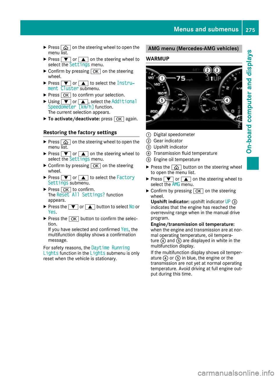
WARMUP
:Digital speedometer
;Gear indicator
=Upshift indicator
?Transmission fluid temperature
AEngine oil temperature
XPress the òbutton on the steering wheel
to open the menu list.
XPress :or9 on the steering wheel to
select the AMGmenu.
XConfirm by pressing aon the steering
wheel.
Upshift indicator: upshift indicatorUP
=
indicates that the engine has reached the
overrevving range when in the manual drive
program.
Engine/transmission oil temperature:
when the engine and transmission are at nor-
mal operating temperature, oil tempera-
ture ?and Aare displayed in white in the
multifunction display.
If the multifunction display shows oil temper-
ature ?orA in blue, the engine or the
transmission are not yet at normal operating
temperature. Avoid driving at full engine out-
put during this time.
Menus and submenus275
On-board computer and displays
Z
Page 360 of 438

iThe ASSYST PLUS service interval display
does not show any information on the engine
oil level. Observe the notes on the engine oil
level (
Ypage 353).
The multifunction display shows a service mes-
sage for several seconds, e.g.:
RService A in XX Days
RService A Due
RService A Overdue by XX Days
Depending on the operating conditions of the
vehicle, the remaining time or distance until the
next service due date is displayed.
The letter A
orB, possibly in connection with a
number or another letter, indicates the type of
service. A
stands for a minor service and Bfor a
major service.
You can obtain further information from an
authorized Mercedes-Benz Center.
The ASSYST PLUS service interval display does
not take into account any periods of time during
which the battery is disconnected.
Maintaining the time-dependent service sched-
ule:
XNote down the service due date displayed in
the multifunction display before disconnect-
ing the battery.
or
XAfter reconnecting the battery, subtract the
battery disconnection periods from the ser-
vice date shown on the display.
Hiding a service message
XPress the aor% button on the steering
wheel.
Displaying service messages
XSwitch the ignition on.
XUse ò on the steering wheel to call up the
list of menus.
XPress 9or: on the steering wheel to
select the Servicemenu and confirm with
a.
XPress 9or: on the steering wheel to
select the ASSYST PLUSsubmenu and con-
firm with a.
The service due date appears in the multi-
function display.
Information about Service
Resetting the ASSYST PLUS service
interval display
!If the ASSYST PLUS service interval display
has been inadvertently reset, this setting can
be corrected at a qualified specialist work-
shop.
Have service work carried out as described in
the Maintenance Booklet. This may otherwise
lead to increased wear and damage to the
major assemblies or the vehicle.
A qualified specialist workshop, e.g. an author-
ized Mercedes-Benz Center, will reset the
ASSYST PLUS service interval display after the
service work has been carried out. You can also
obtain further information on maintenance
work, for example.
Special service requirements
The specified maintenance interval takes only
the normal operation of the vehicle into
account. Under arduous operating conditions or
increased load on the vehicle, maintenance
work must be carried out more frequently, for
example:
Rregular city driving with frequent intermediate
stops
Rif the vehicle is primarily used to travel short
distances
Ruse in mountainous terrain or on poor road
surfaces
Rif the engine is often left idling for long periods
Under these or similar conditions, have, for
example, the air filter, engine oil and oil filter
replaced or changed more frequently. Under
arduous operating conditions, the tires must be
checked more often. Further information can be obtained at a qualified specialist workshop, e.g.
an authorized Mercedes-Benz Center.
Driving abroad
An extensive Mercedes-Benz Service network is
also available in other countries. You can obtain
further information from any authorized
Mercedes-Benz Center.
358ASSYST PLUS
Maintenance and care
Page 382 of 438

PLUG-IN HYBRID vehicles may not be towed
away but must instead be transported, if:
Rthe multifunction display is not working or
Rtheá Towing Not Permitted SeeOperator'sManualmessage appears in the
multifunction display.
If the vehicle is in a dangerous area, it can be
towed out of that area with both axles on the
ground. In this case, the towing distance must
not be greater than 165 ft (50 m)and must not
exceed a towing speed of 6 mph (10 km/h). For
longer distances, have the vehicle loaded and
transported.
Installing/removing the towing eye
Installing the towing eye
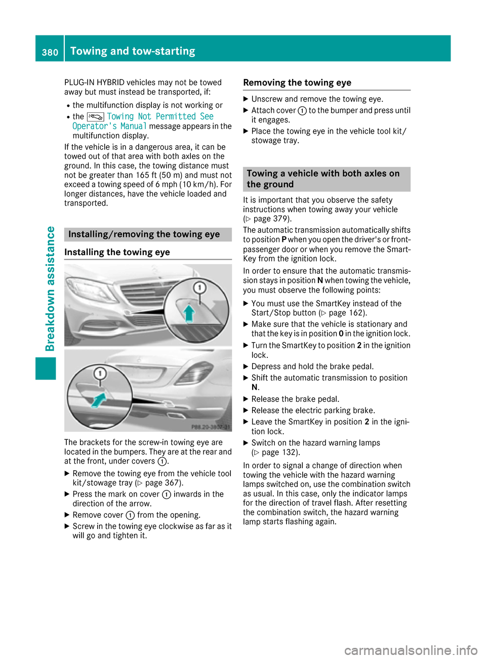
The brackets for the screw-in towing eye are
located in the bumpers. They are at the rear and
at the front, under covers :.
XRemove the towing eye from the vehicle tool
kit/stowage tray (Ypage 367).
XPress the mark on cover:inwards in the
direction of the arrow.
XRemove cover :from the opening.
XScrew in the towing eye clockwise as far as it
will go and tighten it.
Removing the towing eye
XUnscrew and remove the towing eye.
XAttach cover :to the bumper and press until
it engages.
XPlace the towing eye in the vehicle tool kit/
stowage tray.
Towing a vehicle with both axles on
the ground
It is important that you observe the safety
instructions when towing away your vehicle
(
Ypage 379).
The automatic transmission automatically shifts
to position Pwhen you open the driver's or front-
passenger door or when you remove the Smart-
Key from the ignition lock.
In order to ensure that the automatic transmis-
sion stays in position Nwhen towing the vehicle,
you must observe the following points:
XYou must use the SmartKey instead of the
Start/Stop button (Ypage 162).
XMake sure that the vehicle is stationary and
that the key is in position 0in the ignition lock.
XTurn the SmartKey to position 2in the ignition
lock.
XDepress and hold the brake pedal.
XShift the automatic transmission to position
N .
XRelease the brake pedal.
XRelease the electric parking brake.
XLeave the SmartKey in position 2in the igni-
tion lock.
XSwitch on the hazard warning lamps
(Ypage 132).
In order to signal a change of direction when
towing the vehicle with the hazard warning
lamps switched on, use the combination switch
as usual. In this case, only the indicator lamps
for the direction of travel flash. After resetting
the combination switch, the hazard warning
lamp starts f
lashing again.
380Towing and tow-starting
Breakdown assistance
Page 390 of 438

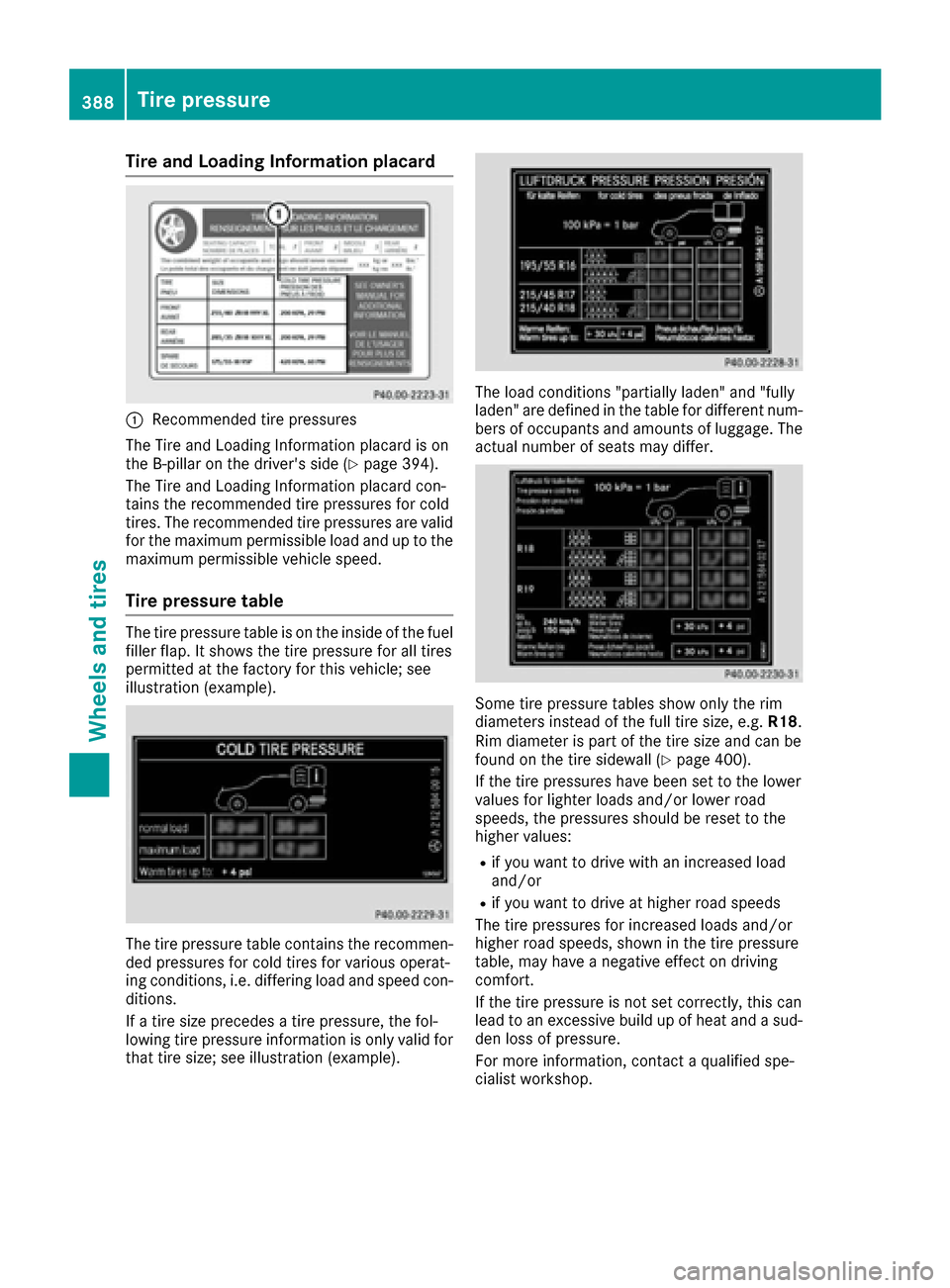
Tire and Loading Information placard
:Recommended tire pressures
The Tire and Loading Information placard is on
the B-pillar on the driver's side (
Ypage 394).
The Tire and Loading Information placard con-
tains the recommended tire pressures for cold
tires. The recommended tire pressures are valid
for the maximum permissible load and up to the
maximum permissible vehicle speed.
Tire pressure table
The tire pressure table is on the inside of the fuel
filler flap. It shows the tire pressure for all tires
permitted at the factory for this vehicle; see
illustration (example).
The tire pressure table contains the recommen-
ded pressures for cold tires for various operat-
ing conditions, i.e. differing load and speed con-
ditions.
If a tire size precedes a tire pressure, the fol-
lowing tire pressure information is only valid for that tire size; see illustration (example).
The load conditions "partially laden" and "fully
laden" are defined in the table for different num-
bers of occupants and amounts of luggage. The
actual number of seats may differ.
Some tire pressure tables show only the rim
diameters instead of the full tire size, e.g. R18.
Rim diameter is part of the tire size and can be
found on the tire sidewall (
Ypage 400).
If the tire pressures have been set to the lower
values for lighter loads and/or lower road
speeds, the pressures should be reset to the
higher values:
Rif you want to drive with an increased load
and/or
Rif you want to drive at higher road speeds
The tire pressures for increased loads and/or
higher road speeds, shown in the tire pressure
table, may have a negative effect on driving
comfort.
If the tire pressure is not set correctly, this can
lead to an excessive build up of heat and a sud-
den loss of pressure.
For more information, contact a qualified spe-
cialist workshop.
388Tire pressure
Wheels and tires