Page 382 of 438

PLUG-IN HYBRID vehicles may not be towed
away but must instead be transported, if:
Rthe multifunction display is not working or
Rtheá Towing Not Permitted SeeOperator'sManualmessage appears in the
multifunction display.
If the vehicle is in a dangerous area, it can be
towed out of that area with both axles on the
ground. In this case, the towing distance must
not be greater than 165 ft (50 m)and must not
exceed a towing speed of 6 mph (10 km/h). For
longer distances, have the vehicle loaded and
transported.
Installing/removing the towing eye
Installing the towing eye
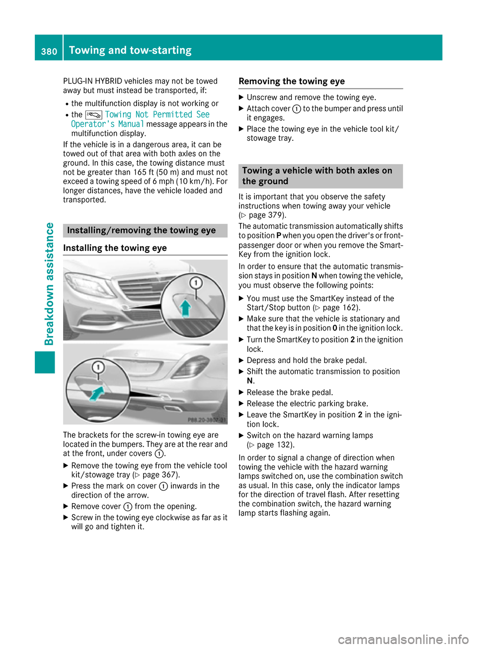
The brackets for the screw-in towing eye are
located in the bumpers. They are at the rear and
at the front, under covers :.
XRemove the towing eye from the vehicle tool
kit/stowage tray (Ypage 367).
XPress the mark on cover:inwards in the
direction of the arrow.
XRemove cover :from the opening.
XScrew in the towing eye clockwise as far as it
will go and tighten it.
Removing the towing eye
XUnscrew and remove the towing eye.
XAttach cover :to the bumper and press until
it engages.
XPlace the towing eye in the vehicle tool kit/
stowage tray.
Towing a vehicle with both axles on
the ground
It is important that you observe the safety
instructions when towing away your vehicle
(
Ypage 379).
The automatic transmission automatically shifts
to position Pwhen you open the driver's or front-
passenger door or when you remove the Smart-
Key from the ignition lock.
In order to ensure that the automatic transmis-
sion stays in position Nwhen towing the vehicle,
you must observe the following points:
XYou must use the SmartKey instead of the
Start/Stop button (Ypage 162).
XMake sure that the vehicle is stationary and
that the key is in position 0in the ignition lock.
XTurn the SmartKey to position 2in the ignition
lock.
XDepress and hold the brake pedal.
XShift the automatic transmission to position
N .
XRelease the brake pedal.
XRelease the electric parking brake.
XLeave the SmartKey in position 2in the igni-
tion lock.
XSwitch on the hazard warning lamps
(Ypage 132).
In order to signal a change of direction when
towing the vehicle with the hazard warning
lamps switched on, use the combination switch
as usual. In this case, only the indicator lamps
for the direction of travel flash. After resetting
the combination switch, the hazard warning
lamp starts f
lashing again.
380Towing and tow-starting
Breakdown assistance
Page 408 of 438

Mounting a wheel
Preparing the vehicle
XStop the vehicle on solid, non-slippery and
level ground.
XApply the electric parking brake manually.
XBring the front wheels into the straight-ahead position.
XShift the transmission to position P.
XMake sure that "normal" level is selected for
AIRMATIC (Ypage 212) or Active Body Con-
trol (ABC) (Ypage 210).
XSwitch off the engine.
XOpen the driver's door.
The on-board electronics now have status 0.
This is the same as the SmartKey having been
removed.
XRemove Start/Stop button from ignition lock (Ypage 162).
or, if the SmartKey is inserted in the ignition
lock:
XRemove the SmartKey from the ignition lock.
XMake sure that the engine cannot be started
via your smartphone (Ypage 164).
XIf included in the vehicle equipment, remove
the tire-change tool kit from the vehicle.
XSafeguard the vehicle against rolling away.
Securing the vehicle to prevent it from
rolling away
If your vehicle is equipped with a wheel chock, it can be found in the tire-change tool kit
(
Ypage 367).
The folding wheel chock is an additional safety
measure to prevent the vehicle from rolling
away, for example when changing a wheel.
XFold both plates upwards :.
XFold out lower plate;.
XGuide the lugs on the lower plate fully into the
openings in base plate =.
XPlace chocks or other suitable items under
the front and rear of the wheel that is diago-
nally opposite the wheel you wish to change.
Raising the vehicle
GWARNING
If you do not position the jack correctly at the
appropriate jacking point of the vehicle, the
jack could tip over with the vehicle raised.
There is a risk of injury.
Only position the jack at the appropriate jack-
ing point of the vehicle. The base of the jack
must be positioned vertically, directly under
the jacking point of the vehicle.
!The jack is designed exclusively for jacking
up the vehicle at the jacking points. Other-
wise, your vehicle could be damaged.
Observe the following when raising the vehi-
cle:
RTo raise the vehicle, only use the vehicle-spe-
cific jack that has been tested and approved
by Mercedes-Benz. If used incorrectly, the
jack could tip over with the vehicle raised.
RThe jack is designed only to raise and hold the
vehicle for a short time while a wheel is being
changed. It must not be used for performing
maintenance work under the vehicle.
RAvoid changing the wheel on uphill and down- hill slopes.
RBefore raising the vehicle, secure it from roll-
ing away by applying the parking brake and
406Changing a wheel
Wheels and tires
Page 429 of 438

iThe data shown on the vehicle identification
plate is used only as an example. This data is
different for every vehicle and can deviate
from the data shown here. You can find the
data applicable to your vehicle on the vehicle
identification plate.
Vehicle identification number (VIN)
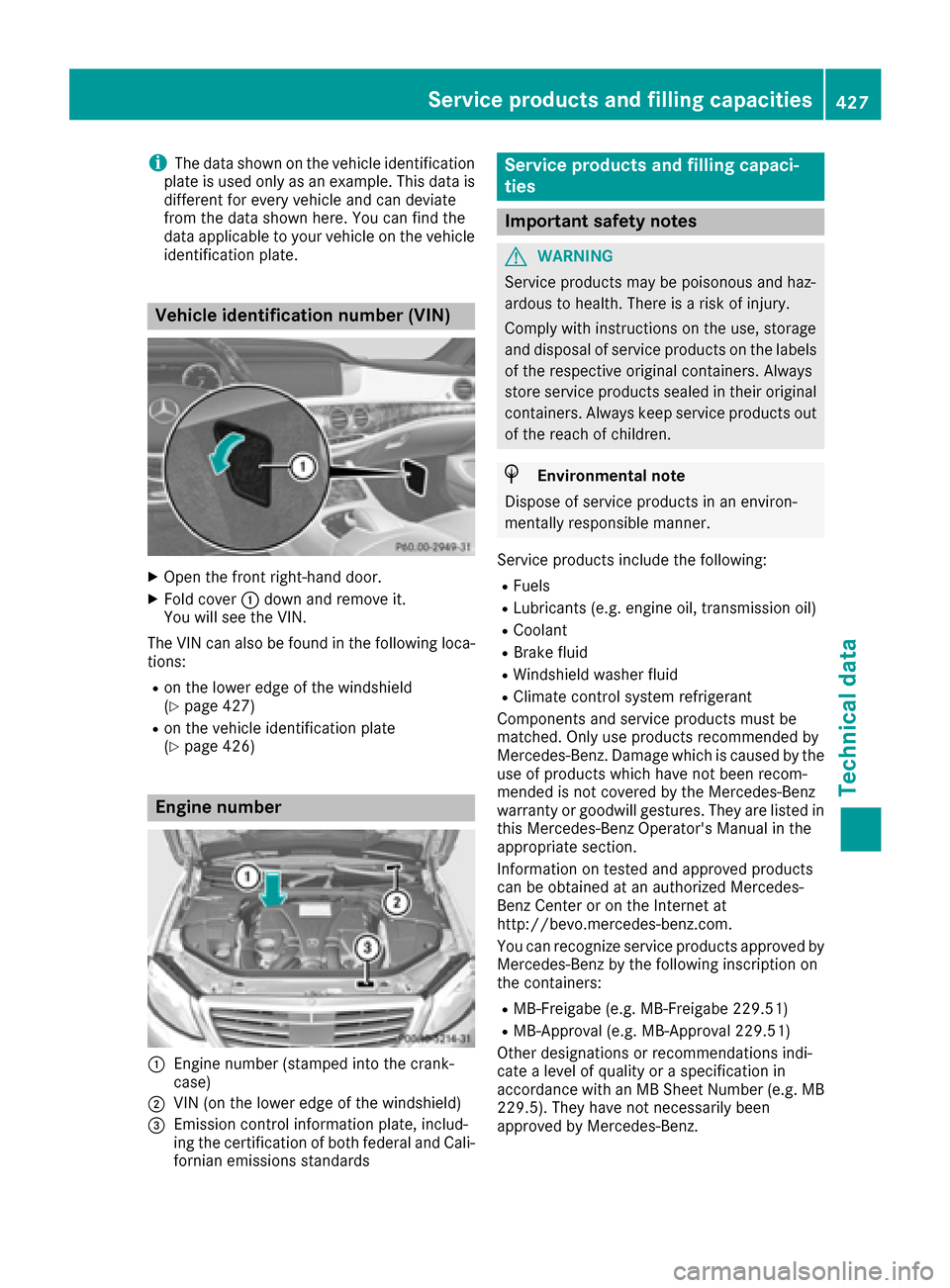
XOpen the front right-hand door.
XFold cover :down and remove it.
You will see the VIN.
The VIN can also be found in the following loca-
tions:
Ron the lower edge of the windshield
(Ypage 427)
Ron the vehicle identification plate
(Ypage 426)
Engine number
:Engine number (stamped into the crank-
case)
;VIN (on the lower edge of the windshield)
=Emission control information plate, includ-
ing the certification of both federal and Cali-
fornian emissions standards
Service products and filling capaci-
ties
Important safety notes
GWARNING
Service products may be poisonous and haz-
ardous to health. There is a risk of injury.
Comply with instructions on the use, storage
and disposal of service products on the labels
of the respective original containers. Always
store service products sealed in their original
containers. Always keep service products out
of the reach of children.
HEnvironmental note
Dispose of service products in an environ-
mentally responsible manner.
Service products include the following:
RFuels
RLubricants (e.g. engine oil, transmission oil)
RCoolant
RBrake fluid
RWindshield washer fluid
RClimate control system refrigerant
Components and service products must be
matched. Only use products recommended by
Mercedes-Benz. Damage which is caused by the
use of products which have not been recom-
mended is not covered by the Mercedes-Benz
warranty or goodwill gestures. They are listed in
this Mercedes-Benz Operator's Manual in the
appropriate section.
Information on tested and approved products
can be obtained at an authorized Mercedes-
Benz Center or on the Internet at
http://bevo.mercedes-benz.com.
You can recognize service products approved by
Mercedes-Benz by the following inscription on
the containers:
RMB-Freigabe (e.g. MB-Freigabe 229.51)
RMB-Approval (e.g. MB-Approval 229.51)
Other designations or recommendations indi-
cate a level of quality or a specification in
accordance with an MB Sheet Number (e.g. MB 229.5). They have not necessarily been
approved by Mercedes-Benz.
Service products and filling capacities427
Technical data
Z