2016 MERCEDES-BENZ S-Class SEDAN button
[x] Cancel search: buttonPage 186 of 438
Setting the maximum charge current
GWARNING
If the charge current draw via a mains socket
is too high during the charging process, the
external electrical system may overheat.
There is a risk of fire.
Before beginning the charging process, check
the maximum permissible charge current
locally. Consult a qualified expert to do so
where necessary.
If necessary, adjust your vehicle's settings.
!An excessive charge current can blow a fuse
or lead to overheating of the external power
supply. Check whether the external power
supply is compatible with the set charge cur-
rent. If necessary, lower the set charge cur-
rent or use another power socket.
Before starting the charging process at a power
socket, check the maximum permissible charge current for the relevant power socket or the
building.
You can set the maximum permissible charge
current:
Ron the controls of the charging cable
Rin the on-board computer menu
(Ypage 272).
The lower value of the two charge current set-
tings – on the charge cable controls and in the
on-board computer – determines the maximum
charge current. If you cannot set the precise
maximum permitted charge current, select the
next lowest available value.
Only set the maximum permitted charge current in the on-board computer menu if:
Rit is not possible to set the charge current on
the charging cable
Rthe precise maximum permitted charge cur-
rent can only be set via the on-board com-
puter
How to set the maximum permissible charge
current on the charging cable, is described as
follows.
XTo adjust the setting: press button?
repeatedly until the desired setting is selec-
ted in display =.
RTwo LEDs are flashing: minimum setting
RAll LEDs are flashing: maximum setting If, after the charging process, the charging cable
is:
Rleft connected to the power socket, the cur-
rently selected values will be used for the next
charging process.
Rremoved from the power socket, the values
will be reset to the minimum setting for the
next charging process. You may then need to
reset the values of the maximum charge cur-
rent.
iIf the vehicle requires more time than usual
when charging, check the maximum charge
current settings using the controls on the
charging cable or in the on-board comput
er's
menu.
Indicator lamp on the vehicle socket
When the indicator lamp on the vehicle socket
lights up, this means the following:
Indicator
lamp
Flashes
orangeThe connection between the
vehicle and the current
source is being established
before charging begins.
Flashes
greenThe high-voltage battery is
being charged.
Flashes redA malfunction has occurred
while charging.
The indicator lamp goes out
after approximately
90 seconds.
Lights up
orangeA charging break for the high-
voltage battery is taking
place.
The indicator lamp goes out
after approximately
90 seconds.
Lights up
greenThe high-voltage battery is
fully charged.
The indicator lamp goes out
after approximately
90 seconds.
iIf the indicator lamp is off, lock or unlock the
vehicle. The indicator lamp then displays the
current status of the charging process again.
184Charging the high-voltage battery (PLUG-IN HYBRID vehicles)
Driving and parking
Page 187 of 438
Connecting the charging cable
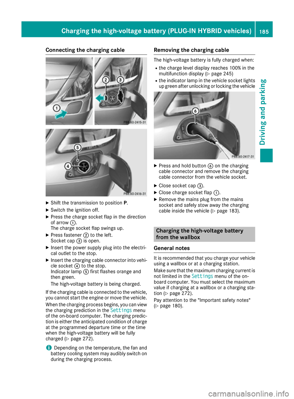
XShift the transmission to positionP.
XSwitch the ignition off.
XPress the charge socket flap in the direction
of arrow:.
The charge socket flap swings up.
XPress fastener ;to the left.
Socket cap =is open.
XInsert the power supply plug into the electri-
cal outlet to the stop.
XInsert the charging cable connector into vehi-
cle socket ?to the stop.
Indicator lamp Afirst flashes orange and
then green.
The high-voltage battery is being charged.
If the charging cable is connected to the vehicle,
you cannot start the engine or move the vehicle.
When the charging process begins, you can view
the charging prediction in the Settings
menu
of the on-board computer. The charging predic-
tion is either the anticipated condition of charge
at the programmed departure time or the time
when the high-voltage battery will be fully
charged (
Ypage 272).
iDepending on the temperature, the fan and
battery cooling system may audibly switch on
during the charging process.
Removing the charging cable
The high-voltage battery is fully charged when:
Rthe charge level display reaches 100% in the
multifunction display (Ypage 245)
Rthe indicator lamp in the vehicle socket lights up green after unlocking or locking the vehicle
XPress and hold button Bon the charging
cable connector and remove the charging
cable connector from the vehicle socket.
XClose socket cap =.
XClose charge socket flap :.
XRemove the mains plug from the mains
socket and safely stow away the charging
cable inside the vehicle (
Ypage 183).
Charging the high-voltage battery
from the wallbox
General notes
It is recommended that you charge your vehicle
using a wallbox or at a charging station.
Make sure that the maximum charging current is
not limited in the Settings
menu of the on-
board computer. You must select the maximum
value if charging at a wallbox or a charging sta-
tion (
Ypage 272).
Pay attention to the "Important safety notes"
(
Ypage 180).
Charging the high-voltage battery (PLUG-IN HYBRID vehicles)185
Driving and parking
Z
Page 188 of 438
Connecting the charging cable
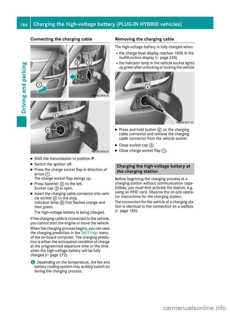
XShift the transmission to positionP.
XSwitch the ignition off.
XPress the charge socket flap in direction of
arrow:.
The charge socket flap swings up.
XPress fastener ;to the left.
Socket cap =is open.
XInsert the charging cable connector into vehi-
cle socket ?to the stop.
Indicator lamp Afirst flashes orange and
then green.
The high-voltage battery is being charged.
If the charging cable is connected to the vehicle,
you cannot start the engine or move the vehicle.
When the charging process begins, you can view
the charging prediction in the Settings
menu
of the on-board computer. The charging predic-
tion is either the anticipated condition of charge
at the programmed departure time or the time
when the high-voltage battery will be fully
charged (
Ypage 272).
iDepending on the temperature, the fan and
battery cooling system may audibly switch on
during the charging process.
Removing the charging cable
The high-voltage battery is fully charged when:
Rthe charge level display reaches 100% in the
multifunction display (Ypage 245)
Rthe indicator lamp in the vehicle socket lights up green after unlocking or locking the vehicle
XPress and hold button Bon the charging
cable connector and remove the charging
cable connector from the vehicle socket.
XClose socket cap =.
XClose charge socket flap :.
Charging the high-voltage battery at
the charging station
Before beginning the charging process at a
charging station without communication capa-
bilities, you must first activate the station, e.g.
using an RFID card. Observe the on-site opera-
tor instructions for the charging station.
The connection for the vehicle at a charging sta-
tion is identical to the connection on a wallbox
(
Ypage 185).
186Charging the high-voltage battery (PLUG-IN HYBRID vehicles)
Driving and parking
Page 190 of 438
ProblemPossible causes/consequences andMSolutions
The indicator lamp on the vehicle socket does not light up.
No connection can be established between the vehicle and the exter-
nal power source.
XConnect the charging cable once again.
If the problem persists:
XHave the mains socket checked for correct function or use another
mains socket.
or
XUse a different charging station.
or
XConsult a qualified specialist workshop.
The charging cable con-
nector cannot be
removed from the vehi-
cle socket.The snap fastener on the charging cable connector is locked.
XPress and hold the button on the charging cable connector. The
snap fastener on the vehicle socket is unlocked.
XRemove the charging cable connector from the vehicle socket.
If the snap fastener on the charging cable connector is locked:
XPress and hold the button on the charging cable connector and try
to release the lock.
Online access to the vehicle
General information
GWARNING
If you operate information systems and com-
munication equipment integrated in the vehi-
cle while driving, you will be distracted from
traffic conditions. You could also lose control
of the vehicle. There is a risk of an accident.
Only operate the equipment when the traffic
situation permits. If you are not sure that this
is possible, park the vehicle paying attention
to traffic conditions and operate the equip-
ment when the vehicle is stationary.
iOperation of integrated information sys-
tems and communications equipment in
the vehicle: you must observe the legal
requirements for the country in which you are currently driving.
Via the "My Mercedes Electric - Vehicle Home-
page", you can call up remote query and remote
configuration functions for your vehicle. This is possible from an Internet-enabled computer, as
well as many modern smartphones.
Please call the Mercedes-Benz Customer Assis-
tance Center (USA) at the hotline number
1-800-FOR-MERCedes (1-800-367-6372)
to
obtain the relevant Internet address.
Access to "My Mercedes Electric - Vehicle
Homepage" is dependent on the contractual
periods of mbrace. Activated access to the
mbrace emergency call system is required for
use.
In order to use the "My Mercedes Electric - Vehi-
cle Homepage ", you must agree to the local
terms of use.
Further information on supported devices, avail-
able languages and contractual periods can be
obtained from any authorized Mercedes-Benz
Center.
In order to call up the "Mercedes Electric - Vehi-
cle Homepage", the vehicle must be connected
to the Internet (
Ypage 189).
Notes on data protection
Bear in mind that the "My Mercedes Electric -
Vehicle Homepage" offers access to your data.
188Charging the high-voltage battery (PLUG-IN HYBRID vehicles)
Driving and parking
Page 192 of 438
Switching off the engine
Important safety notes
GWARNING
The automatic transmission switches to neu-
tral position Nwhen you switch off the engine.
The vehicle may roll away. There is a risk of an
accident.
After switching off the engine, always switch
to parking position P. Prevent the parked vehi-
cle from rolling away by applying the parking
brake.
Using the SmartKey
XApply the electric parking brake.
XShift the transmission to position P.
XTurn the SmartKey to position0in the ignition
lock and remove it.
The immobilizer is activated.
If you switch the engine off with the trans-
mission in position Ror D, the automatic
transmission shifts to Nautomatically.
If you then open the driver's door or the front-
passenger door or remove the SmartKey from the ignition, the automatic transmission shifts
to Pautomatically.
If you want the automatic transmission to
remain in neutral N, e.g. when having the vehicle
cleaned in an automatic car wash with a towing system:
XSwitch on the ignition.
XDepress the brake pedal and keep it
depressed.
XShift to neutral N.
XRelease the brake pedal.
XRelease the electric parking brake.
XSwitch off the ignition and leave the SmartKey
in the ignition lock.
Using the Start/Stop button
XApply the electric parking brake.
XShift the transmission to position P.
XPress the Start/Stop button (Ypage 162)
The engine stops and all the indicator lamps in
the instrument cluster go out. When the driver's door is closed, this corre-
sponds to SmartKey position
1. When the
driver's door is open, this corresponds to
SmartKey position 0: "SmartKey removed".
If you switch the engine off with the transmis-
sion in position Ror D, the automatic transmis-
sion shifts to Nautomatically.
If you then open the driver's or front-passenger door, the automatic transmission shifts to P
automatically.
If you want the automatic transmission to
remain in neutral N, e.g. when having the vehicle
cleaned in an automatic car wash with a towing
system:
XSwitch on the ignition.
XDepress the brake pedal and keep it
depressed.
XRemove the Start/Stop button from the igni-
tion lock.
XInsert the SmartKey into the ignition lock.
XShift to neutral N.
XRelease the brake pedal.
XRelease the electric parking brake.
XSwitch off the ignition and leave the SmartKey
in the ignition lock.
The engine can be switched off in an emergency
while the vehicle is in motion by pressing and
holding the Start/Stop button for three sec-
onds. This function operates independently of
the ECO start/stop automatic engine switch-off
function.
Electric parking brake
General notes
GWARNING
If you leave children unsupervised in the vehi-
cle, they could set it in motion by, for example:
Rrelease the parking brake.
Rshift the automatic transmission out of the
parking position P.
Rstart the engine.
In addition, they may operate vehicle equip-
ment and become trapped. There is a risk of
an accident and injury.
190Parking
Driving and parking
Page 193 of 438
When leaving the vehicle, always take the
SmartKey with you and lock the vehicle. Never
leave children unsupervised in the vehicle.
The function of the electric parking brake is
dependent on the on-board voltage. If the on-
board voltage is low or there is a malfunction in
the system, it may not be possible to apply the
released parking brake.
XIf this is the case, only park the vehicle on
level ground and secure it to prevent it rolling
away.
XShift the automatic transmission to position
P.
It may not be possible to release an applied
parking brake if the on-board voltage is low or
there is a malfunction in the system. Contact a
qualified specialist workshop.
The electric parking brake performs a function
test at regular intervals while the engine is
switched off. The sounds that can be heard while
this is occurring are normal.
Applying or releasing manually
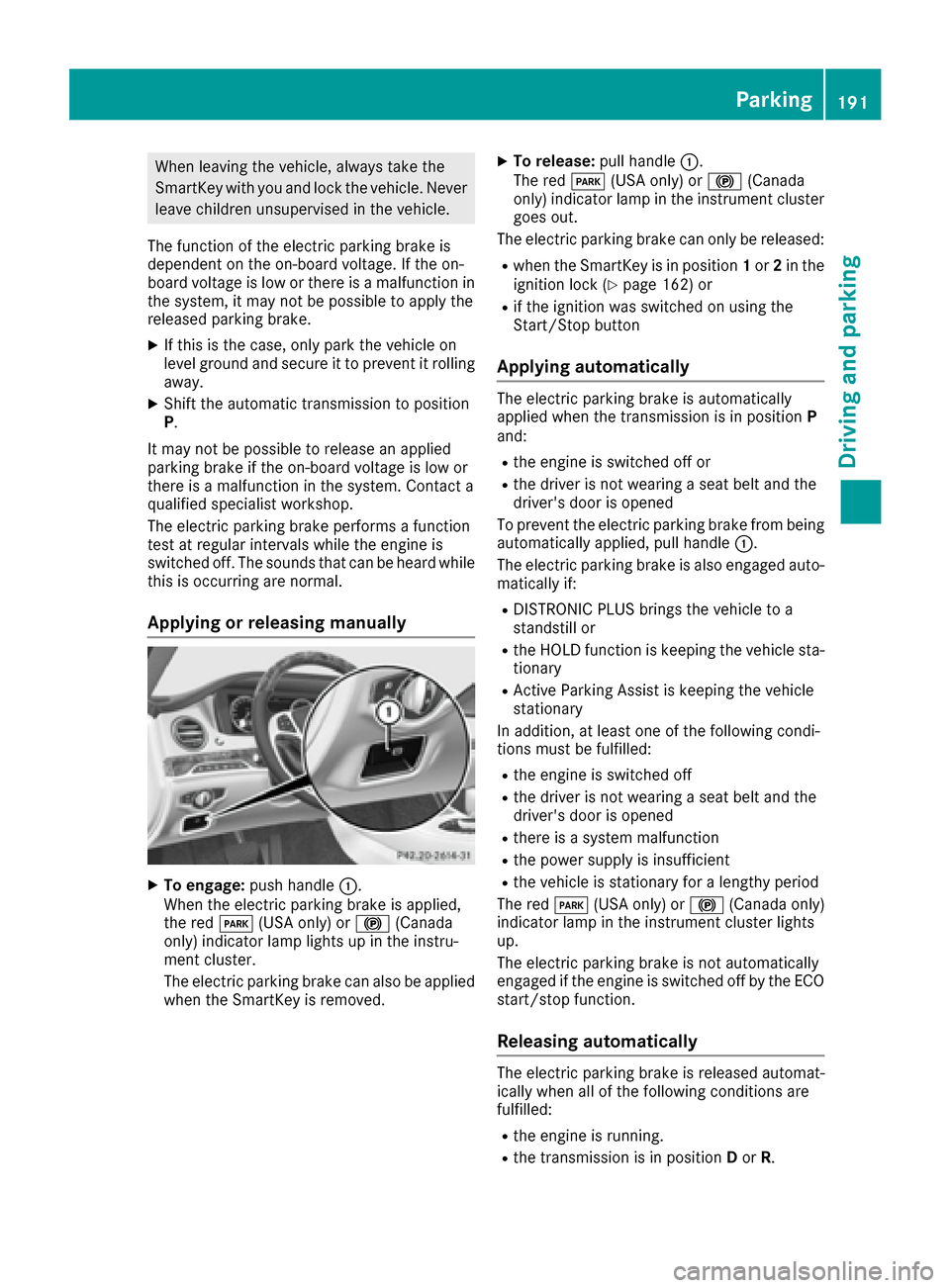
XTo engage: push handle :.
When the electric parking brake is applied,
the red F(USA only) or !(Canada
only) indicator lamp lights up in the instru-
ment cluster.
The electric parking brake can also be applied
when the SmartKey is removed.
XTo release: pull handle:.
The red F(USA only) or !(Canada
only) indicator lamp in the instrument cluster
goes out.
The electric parking brake can only be released:
Rwhen the SmartKey is in position 1or 2in the
ignition lock (Ypage 162) or
Rif the ignition was switched on using the
Start/Stop button
Applying automatically
The electric parking brake is automatically
applied when the transmission is in position P
and:
Rthe engine is switched off or
Rthe driver is not wearing a seat belt and the
driver's door is opened
To prevent the electric parking brake from being
automatically applied, pull handle :.
The electric parking brake is also engaged auto- matically if:
RDISTRONIC PLUS brings the vehicle to a
standstill or
Rthe HOLD function is keeping the vehicle sta-
tionary
RActive Parking Assist is keeping the vehicle
stationary
In addition, at least one of the following condi-
tions must be fulfilled:
Rthe engine is switched off
Rthe driver is not wearing a seat belt and the
driver's door is opened
Rthere is a system malfunction
Rthe power supply is insufficient
Rthe vehicle is stationary for a lengthy period
The red F(USA only) or !(Canada only)
indicator lamp in the instrument cluster lights
up.
The electric parking brake is not automatically
engaged if the engine is switched off by the ECO
start/stop function.
Releasing automatically
The electric parking brake is released automat-
ically when all of the following conditions are
fulfilled:
Rthe engine is running.
Rthe transmission is in position Dor R.
Parking191
Driving and parking
Z
Page 197 of 438
Limited braking performance on salt-
treated roads
If you drive on salted roads, a layer of salt resi-
due may form on the brake discs and brake
pads. This can result in a significantly longer
braking distance.
RIn order to prevent any salt build-up, apply the
brakes occasionally while paying attention to the traffic conditions.
RCarefully depress the brake pedal and the
beginning and end of a journey.
RMaintain a greater distance to the vehicle
ahead.
Servicing the brakes
!The brake fluid level may be too low, if:
Rif the red brake warning lamp lights up in
the instrument cluster and
Ryou hear a warning tone while the engine is
running
Observe additional warning messages in the
multifunction display.
The brake fluid level may be too low due to
brake pad wear or leaking brake lines.
Have the brake system checked immediately.
Consult a qualified specialist workshop to
arrange this.
!Vehicles with 4MATIC: function or per-
formance tests may only be carried out on a 2-
axle dynamometer. If you wish to operate the
vehicle on such a dynamometer, please con-
sult a qualified specialist workshop in
advance. You could otherwise damage the
drive train or the brake system.
!Vehicles with 4MATIC: the ESP®system
operates automatically. The engine and the
ignition must therefore be switched off (the
SmartKey must be in position 0or 1in the
ignition lock or the Start/Stop button must be
in position 0or 1) if the electric parking brake
is tested on a brake dynamometer.
Braking triggered automatically by ESP
®may
cause severe damage to the brake system.
!Vehicles without 4MATIC: the ESP®sys-
tem operates automatically. The engine and
the ignition must therefore be switched off
(the SmartKey must be in position 0or 1in the
ignition lock or the Start/Stop button must be
in position 0or 1) if:
Rthe electric parking brake is tested using a
brake dynamometer.
Rthe vehicle is towed with one axle raised.
Braking triggered automatically by ESP®may
cause severe damage to the brake system.
All checks and maintenance work on the brake
system must be carried out at a qualified spe-
cialist workshop.
Have brake pads installed and brake fluid
replaced at a qualified specialist workshop.
If the brake system has only been subject to
moderate loads, you should test the functional-
ity of your brakes at regular intervals.
Information on BAS (Brake Assist) (
Ypage 69)
and BAS PLUS (Brake Assist PLUS) (Ypage 69).
For safety reasons, Mercedes-Benz recom-
mends only installing the following brake disks
and brake pads/linings:
Rbrake disks that have been approved by
Mercedes-Benz
Rbrake pads/linings that have been approved
by Mercedes-Benz or that are of an equivalent
standard of quality
Other brake disks or brake pads/linings can
compromise the safety of your vehicle.
Always replace all brake disks and brake pads/
linings on an axle at the same time. Always
install new brake pads/linings when replacing
brake disks.
The vehicle is equipped with lightweight brake
disks to which the wheel assembly with rim and
threaded connection is matched.
The use of brake disks other than those
approved by Mercedes-Benz can change the
track width and is subject to approval, if appli-
cable.
Shoc
k-type loads when handling the brake
discs, such as when changing wheels, can lead
to a reduction in comfort when driving with light-
weight brake discs. Avoid shock-type loads on
the lightweight brake disks, particularly on the
brake plate.
Mercedes-Benz recommends that you only use
brake fluid that has been specially approved for
your vehicle by Mercedes-Benz, or which corre-
Driving tips195
Driving and parking
Z
Page 210 of 438
iSteering Assist and Stop&Go Pilot are acti-
vated again automatically after a lane change
is completed.
Steering Assist and Stop&Go Pilot do not pro-
vide any support:
Ron very sharp corners
Rwhen a loss of tire pressure or a defective tire
has been detected and displayed
Pay attention also to the important safety notes
for DISTRONIC PLUS (
Ypage 200).
The steering interventions are carried out with a
limited steering moment. The system requires
the driver to keep his hands on the steering
wheel and to steer himself.
If you do not steer yourself or if you take your
hands off the steering wheel for a prolonged
period of time, the system will first alert you with
a visual warning. A steering wheel symbol
appears in the multifunction display. If you have
still not started to steer and have not taken hold
of the steering wheel after five seconds at the
latest, a warning tone also sounds to remind you
to take control of the vehicle. Steering Assist
and Stop&Go Pilot are switched to passive.
DISTRONIC PLUS remains active.
Activating Steering Assist and Stop&Go
Pilot
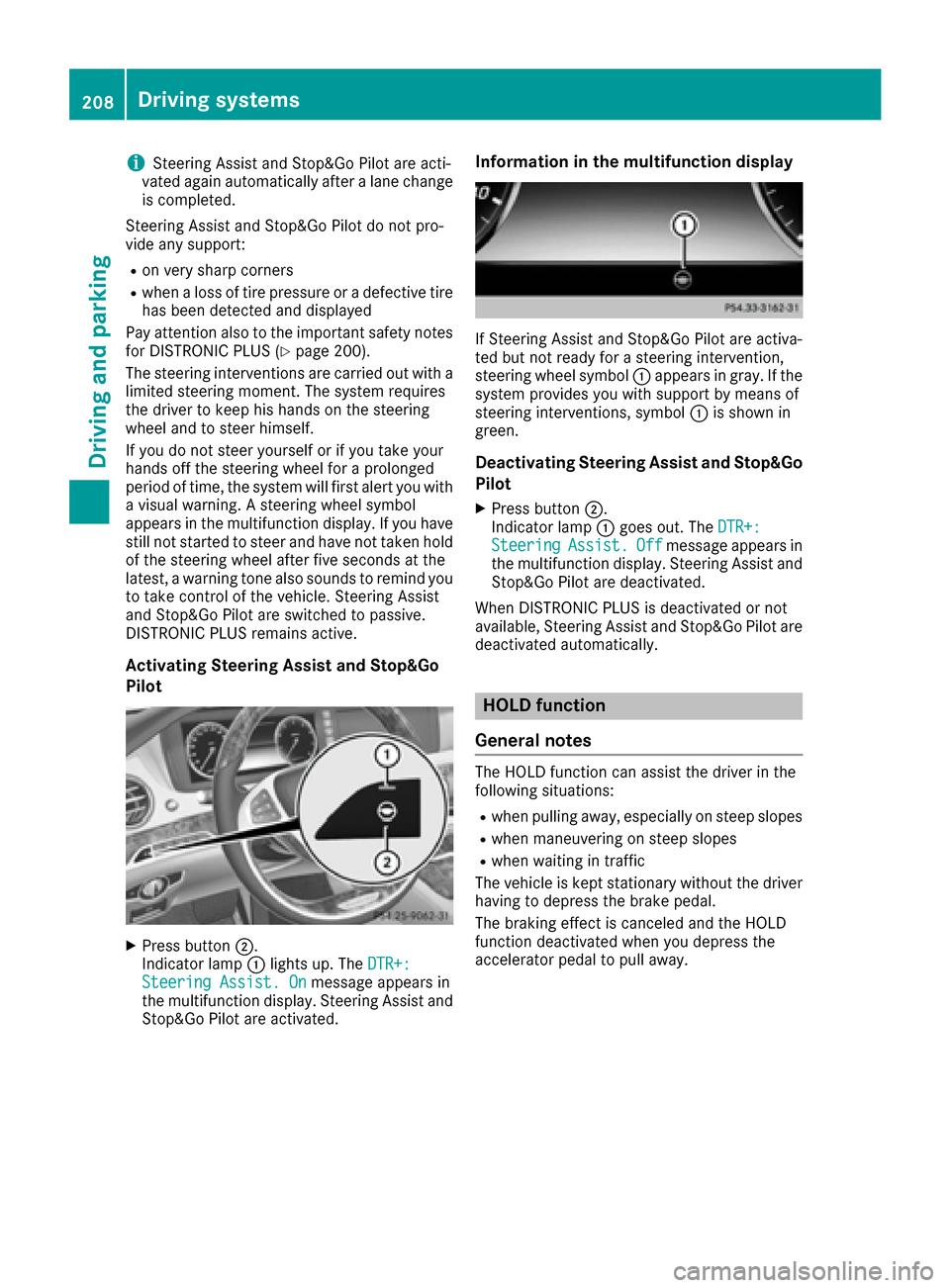
XPress button ;.
Indicator lamp :lights up. The DTR+:
Steering Assist. Onmessage appears in
the multifunction display. Steering Assist and
Stop&Go Pilot are activated.
Information in the multifunction display
If Steering Assist and Stop&Go Pilot are activa-
ted but not ready for a steering intervention,
steering wheel symbol :appears in gray. If the
system provides you with support by means of
steering interventions, symbol :is shown in
green.
Deactivating Steering Assist and Stop&Go
Pilot
XPress button ;.
Indicator lamp :goes out. The DTR+:
SteeringAssist.Offmessage appears in
the multifunction display. Steering Assist and
Stop&Go Pilot are deactivated.
When DISTRONIC PLUS is deactivated or not
available, Steering Assist and Stop&Go Pilot are deactivated automatically.
HOLD function
General notes
The HOLD function can assist the driver in the
following situations:
Rwhen pulling away, especially on steep slopes
Rwhen maneuvering on steep slopes
Rwhen waiting in traffic
The vehicle is kept stationary without the driver having to depress the brake pedal.
The braking effect is canceled and the HOLD
function deactivated when you depress the
accelerator pedal to pull away.
208Driving systems
Driving and parking