2016 MERCEDES-BENZ GLS SUV load capacity
[x] Cancel search: load capacityPage 319 of 397
!
The backrest is heavy. Therefore, exercise
care when folding it down. Make sure that the
head restraints are pushed all the way in so
that the backrests and seat cushions are not
damaged.
Observe the loading guidelines (Y page 312).
The left-hand and right-hand backrests in the
2nd row of seats can be folded forwards sepa-
rately to increase the luggage compartment
capacity.
On vehicles with a third row of seats, you must
fold down the 3rd row of seats beforehand
(Y page 107) to obtain maximum luggage com-
partment enlargement.
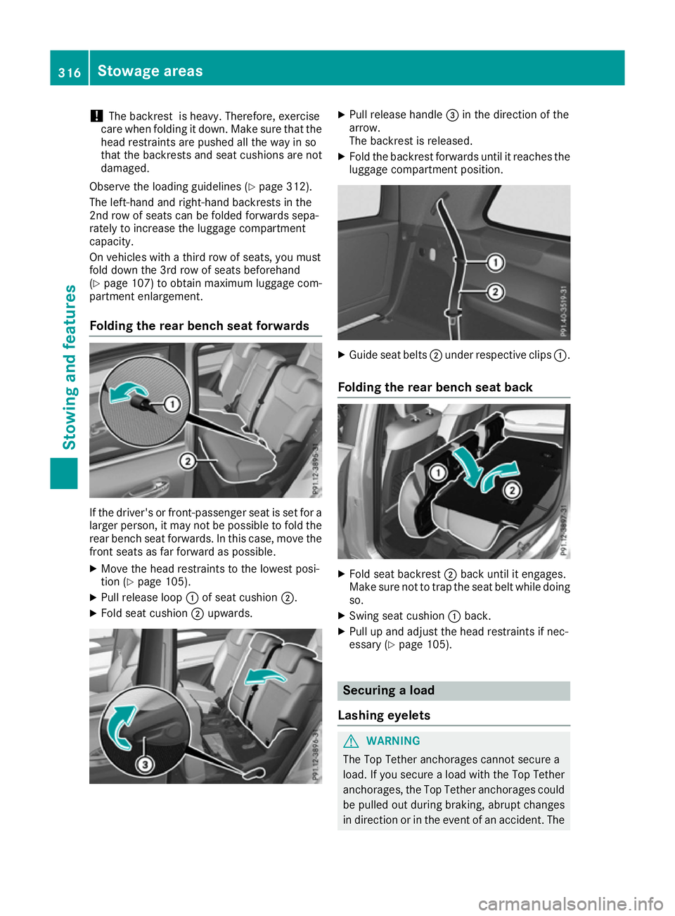
Folding the rear bench seat forwards If the driver's or front-passenger seat is set for a
larger person, it may not be possible to fold the
rear bench seat forwards. In this case, move the front seats as far forward as possible.
X Move the head restraints to the lowest posi-
tion (Y page 105).
X Pull release loop :of seat cushion ;.
X Fold seat cushion ;upwards. X
Pull release handle =in the direction of the
arrow.
The backrest is released.
X Fold the backrest forwards until it reaches the
luggage compartment position. X
Guide seat belts ;under respective clips :.
Folding the rear bench seat back X
Fold seat backrest ;back until it engages.
Make sure not to trap the seat belt while doing so.
X Swing seat cushion :back.
X Pull up and adjust the head restraints if nec-
essary (Y page 105). Securing a load
Lashing eyelets G
WARNING
The Top Tether anchorages cannot secure a
load. If you secure a load with the Top Tether
anchorages, the Top Tether anchorages could be pulled out during braking, abrupt changes
in direction or in the event of an accident. The 316
Stowage areasStowing and features
Page 323 of 397
Depending on the vehicle equipment, ensure
that when the roof carrier is fitted you can:
R raise the sliding sunroof fully
R open the panorama sliding sunroof fully
R open the tailgate fully
You will find information on the maximum roof
load in the "Technical data" section
(Y page 387).
An incorrectly secured roof carrier or roof load
may become detached from the vehicle. You
must therefore ensure that you observe the roof
carrier manufacturer's installation instructions.
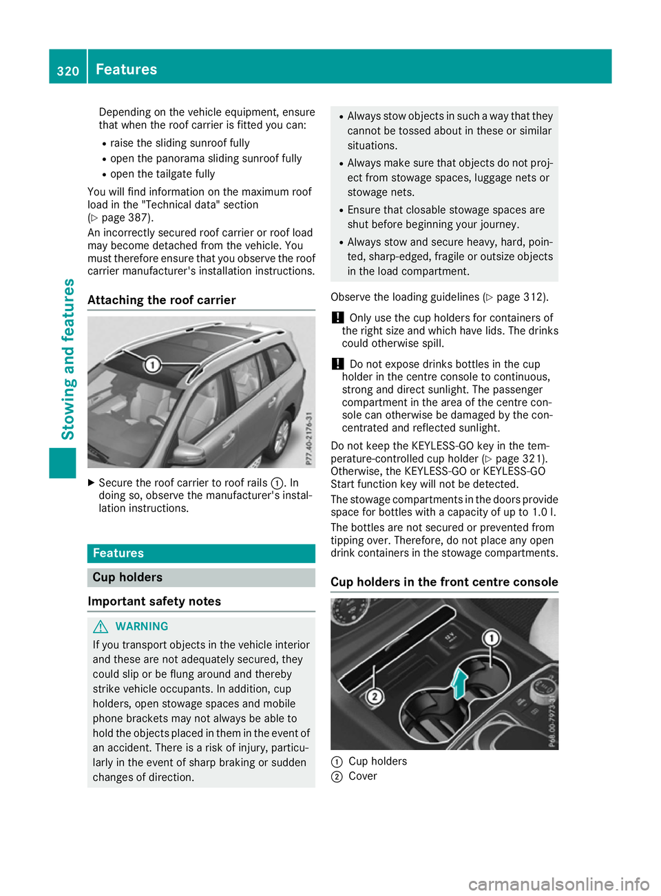
Attaching the roof carrier X
Secure the roof carrier to roof rails :. In
doing so, observe the manufacturer's instal-
lation instructions. Features
Cup holders
Important safety notes G
WARNING
If you transport objects in the vehicle interior and these are not adequately secured, they
could slip or be flung around and thereby
strike vehicle occupants. In addition, cup
holders, open stowage spaces and mobile
phone brackets may not always be able to
hold the objects placed in them in the event of an accident. There is a risk of injury, particu-
larly in the event of sharp braking or sudden
changes of direction. R
Always stow objects in such a way that they
cannot be tossed about in these or similar
situations.
R Always make sure that objects do not proj-
ect from stowage spaces, luggage nets or
stowage nets.
R Ensure that closable stowage spaces are
shut before beginning your journey.
R Always stow and secure heavy, hard, poin-
ted, sharp-edged, fragile or outsize objects
in the load compartment.
Observe the loading guidelines (Y page 312).
! Only use the cup holders for containers of
the right size and which have lids. The drinks
could otherwise spill.
! Do not expose drinks bottles in the cup
holder in the centre console to continuous,
strong and direct sunlight. The passenger
compartment in the area of the centre con-
sole can otherwise be damaged by the con-
centrated and reflected sunlight.
Do not keep the KEYLESS-GO key in the tem-
perature-controlled cup holder (Y page 321).
Otherwise, the KEYLESS-GO or KEYLESS-GO
Start function key will not be detected.
The stowage compartments in the doors provide
space for bottles with a capacity of up to 1.0 l.
The bottles are not secured or prevented from
tipping over. Therefore, do not place any open
drink containers in the stowage compartments.
Cup holders in the front centre console :
Cup holders
; Cover 320
FeaturesStowing and features
Page 349 of 397
the vehicle. For more information on which tools
are required to perform a wheel change on your vehicle, consult a qualified specialist workshop.
Necessary tyre-changing tools may include, for
example:
R jack
R wheel chock
R wheel wrench
R ratchet ring spanner
R centring pin
i The jack weighs approximately 3.4 kg.
The maximum load-bearing capacity of the
jack can be found on the adhesive label on the
jack.
The jack is maintenance-free. If there is a
malfunction, please contact a qualified spe-
cialist workshop.
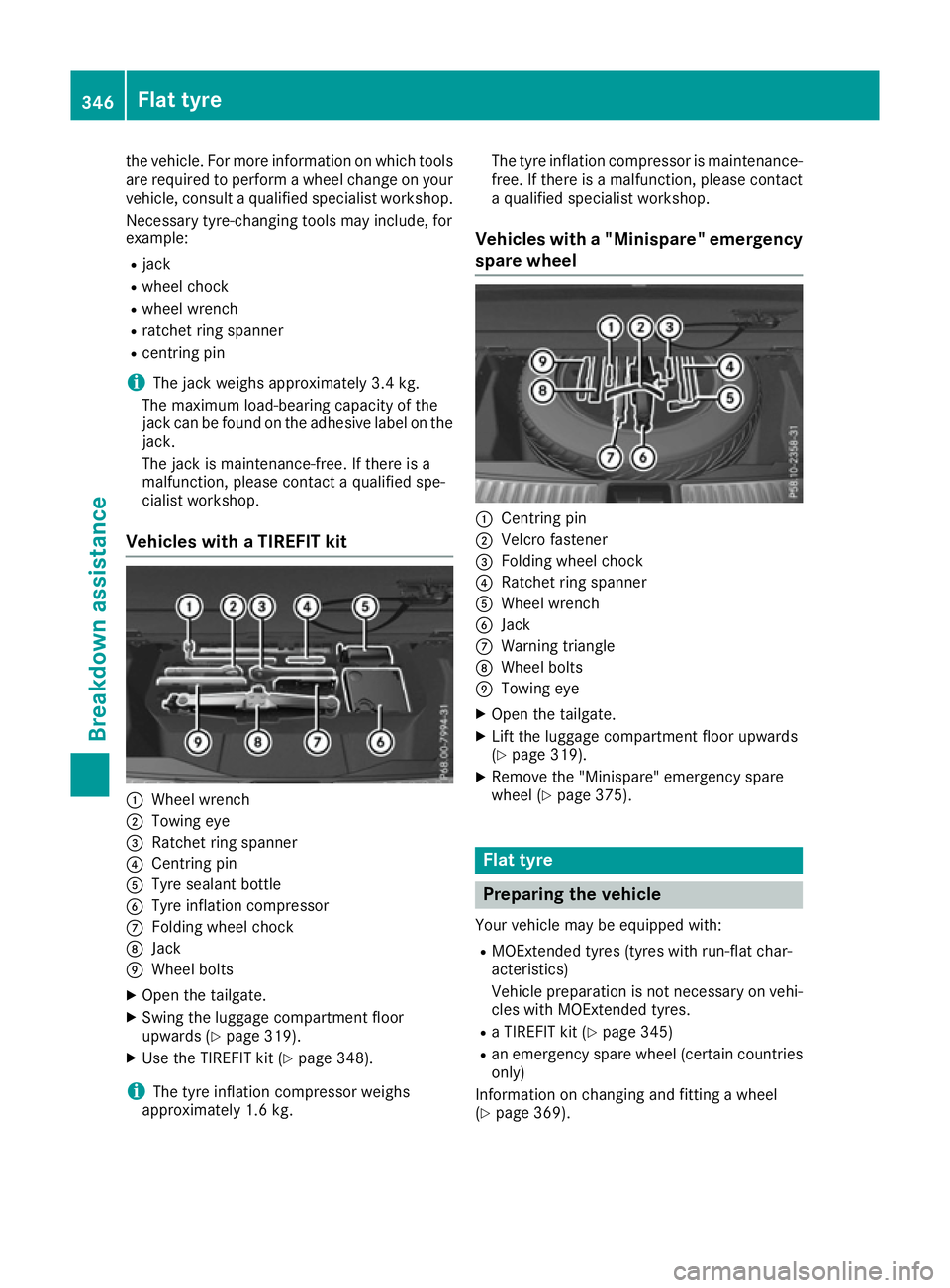
Vehicles with a TIREFIT kit :
Wheel wrench
; Towing eye
= Ratchet ring spanner
? Centring pin
A Tyre sealant bottle
B Tyre inflation compressor
C Folding wheel chock
D Jack
E Wheel bolts
X Open the tailgate.
X Swing the luggage compartment floor
upwards (Y page 319).
X Use the TIREFIT kit (Y page 348).
i The tyre inflation compressor weighs
approximately 1.6 kg. The tyre inflation compressor is maintenance-
free. If there is a malfunction, please contact a qualified specialist workshop.
Vehicles with a "Minispare" emergency
spare wheel :
Centring pin
; Velcro fastener
= Folding wheel chock
? Ratchet ring spanner
A Wheel wrench
B Jack
C Warning triangle
D Wheel bolts
E Towing eye
X Open the tailgate.
X Lift the luggage compartment floor upwards
(Y page 319).
X Remove the "Minispare" emergency spare
wheel (Y page 375). Flat tyre
Preparing the vehicle
Your vehicle may be equipped with: R MOExtended tyres (tyres with run-flat char-
acteristics)
Vehicle preparation is not necessary on vehi- cles with MOExtended tyres.
R a TIREFIT kit (Y page 345)
R an emergency spare wheel (certain countries
only)
Information on changing and fitting a wheel
(Y page 369). 346
Flat tyreBreakdown assistance
Page 350 of 397
X
Stop the vehicle as far away as possible from
traffic on solid, non-slippery and level ground.
X Switch on the hazard warning lamps.
X Safeguard the vehicle against rolling away
(Y page 168).
X If possible, bring the front wheels into the
straight-ahead position.
X Vehicles with the AIRMATIC package:
make sure that the normal vehicle level is
selected (Y page 198).
X Vehicles with the Off-Road Engineering
package:
make sure that the normal level is
selected (Y page 192).
X Switch off the engine.
X Vehicles without KEYLESS-GO: remove the
key from the ignition lock.
X Vehicles with KEYLESS-GO: open the driv-
er's door.
The on-board electronics now have status 0.
This is the same as the key having been
removed.
X Vehicles with KEYLESS-GO: remove the
Start/Stop button from the ignition lock
(Y page 148).
X Make sure that the passengers are not endan-
gered as they do so. Make sure that no one is
near the danger area while a wheel is being
changed. Anyone who is not directly assisting in the wheel change should, for example,
stand behind the barrier.
X Get out of the vehicle. Pay attention to traffic
conditions when doing so.
X Close the driver's door.
X Place the warning triangle at a suitable dis-
tance (Y page 345). Observe legal require-
ments.
X Unload heavy luggage.
i Only operate the tyre inflation compressor
using a 12 V socket, even if the ignition is
turned off (Y page 324).
An emergency cut-off ensures that the on-
board voltage does not drop too low. If the on-
board voltage is too low, the power to the
sockets is automatically cut. This ensures
that there is sufficient power to start the
engine. MOExtended tyres (tyres with run-flat
characteristics)
General notes With MOExtended tyres (tyres with run-flat char-
acteristics), you can continue to drive your vehi- cle even if there is a total loss of pressure in one
or more tyres. The affected tyre must not show
any clearly visible damage.
You can recognise MOExtended tyres by the
MOExtended marking which appears on the tyre wall. You will find this marking next to the tyre
size designation, the load-bearing capacity and
the speed index.
MOExtended tyres may only be used in conjunc-tion with an activated tyre pressure loss warning
system or tyre pressure monitor.
If a pressure loss warning message appears in the multifunction display:
R observe the instructions in the display mes-
sages (Y page 283)
R check the tyre for damage
R if driving on, observe the following notes
The driving distance possible in run-flat mode is
approximately 80 km when the vehicle is parti-
ally laden and approximately 30 km when the
vehicle is fully laden.
In addition to the vehicle load, the driving dis-
tance possible depends upon:
R vehicle speed
R road condition
R outside temperature
The driving distance possible in run-flat mode
may be reduced by extreme driving conditions/
manoeuvres, or it can be increased through a
moderate style of driving.
The driving distance possible in run-flat mode is counted from the moment the tyre pressure loss
warning appears in the multifunction display.
You must not exceed a maximum speed of
80 km/h.
i When replacing one or all tyres, observe the
following specifications for your vehicle's
tyres:
R size
R type and
R the "MOExtended" mark
If a tyre has gone flat and cannot be replaced
with an MOExtended tyre, a standard tyre Flat tyre
347Breakdown assistance
Page 374 of 397
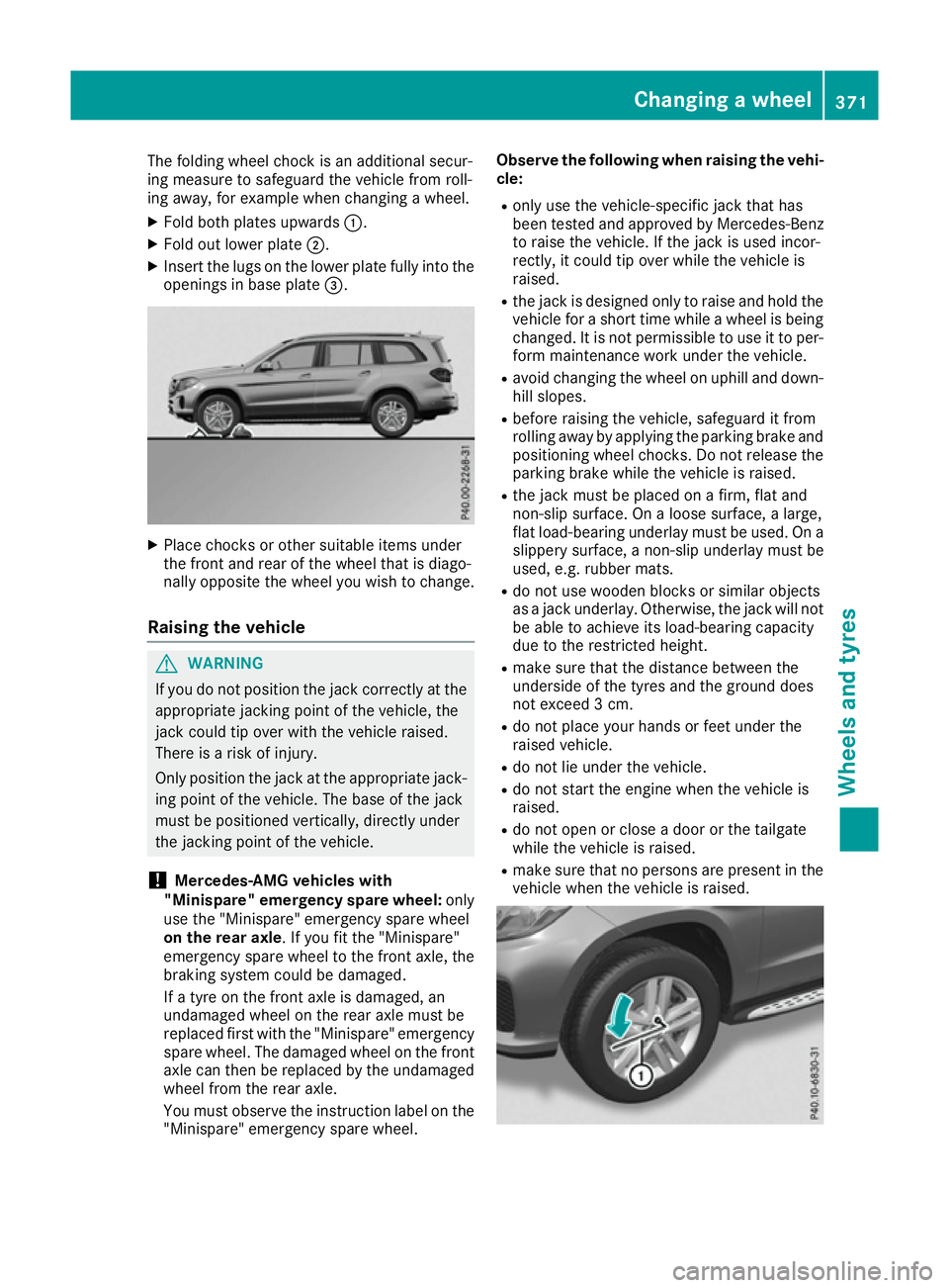
The folding wheel chock is an additional secur-
ing measure to safeguard the vehicle from roll-
ing away, for example when changing a wheel.
X Fold both plates upwards :.
X Fold out lower plate ;.
X Insert the lugs on the lower plate fully into the
openings in base plate =.X
Place chocks or other suitable items under
the front and rear of the wheel that is diago-
nally opposite the wheel you wish to change.
Raising the vehicle G
WARNING
If you do not position the jack correctly at the appropriate jacking point of the vehicle, the
jack could tip over with the vehicle raised.
There is a risk of injury.
Only position the jack at the appropriate jack-
ing point of the vehicle. The base of the jack
must be positioned vertically, directly under
the jacking point of the vehicle.
! Mercedes-AMG vehicles with
"Minispare" emergency spare wheel: only
use the "Minispare" emergency spare wheel
on the rear axle. If you fit the "Minispare"
emergency spare wheel to the front axle, the
braking system could be damaged.
If a tyre on the front axle is damaged, an
undamaged wheel on the rear axle must be
replaced first with the "Minispare" emergency spare wheel. The damaged wheel on the front
axle can then be replaced by the undamaged
wheel from the rear axle.
You must observe the instruction label on the "Minispare" emergency spare wheel. Observe the following when raising the vehi-
cle:
R only use the vehicle-specific jack that has
been tested and approved by Mercedes-Benz
to raise the vehicle. If the jack is used incor-
rectly, it could tip over while the vehicle is
raised.
R the jack is designed only to raise and hold the
vehicle for a short time while a wheel is being
changed. It is not permissible to use it to per- form maintenance work under the vehicle.
R avoid changing the wheel on uphill and down-
hill slopes.
R before raising the vehicle, safeguard it from
rolling away by applying the parking brake and
positioning wheel chocks. Do not release theparking brake while the vehicle is raised.
R the jack must be placed on a firm, flat and
non-slip surface. On a loose surface, a large,
flat load-bearing underlay must be used. On a
slippery surface, a non-slip underlay must be
used, e.g. rubber mats.
R do not use wooden blocks or similar objects
as a jack underlay. Otherwise, the jack will not
be able to achieve its load-bearing capacity
due to the restricted height.
R make sure that the distance between the
underside of the tyres and the ground does
not exceed 3 cm.
R do not place your hands or feet under the
raised vehicle.
R do not lie under the vehicle.
R do not start the engine when the vehicle is
raised.
R do not open or close a door or the tailgate
while the vehicle is raised.
R make sure that no persons are present in the
vehicle when the vehicle is raised. Changing a wheel
371Wheels and tyres Z