2016 MERCEDES-BENZ GLS SUV tailgate
[x] Cancel search: tailgatePage 211 of 397
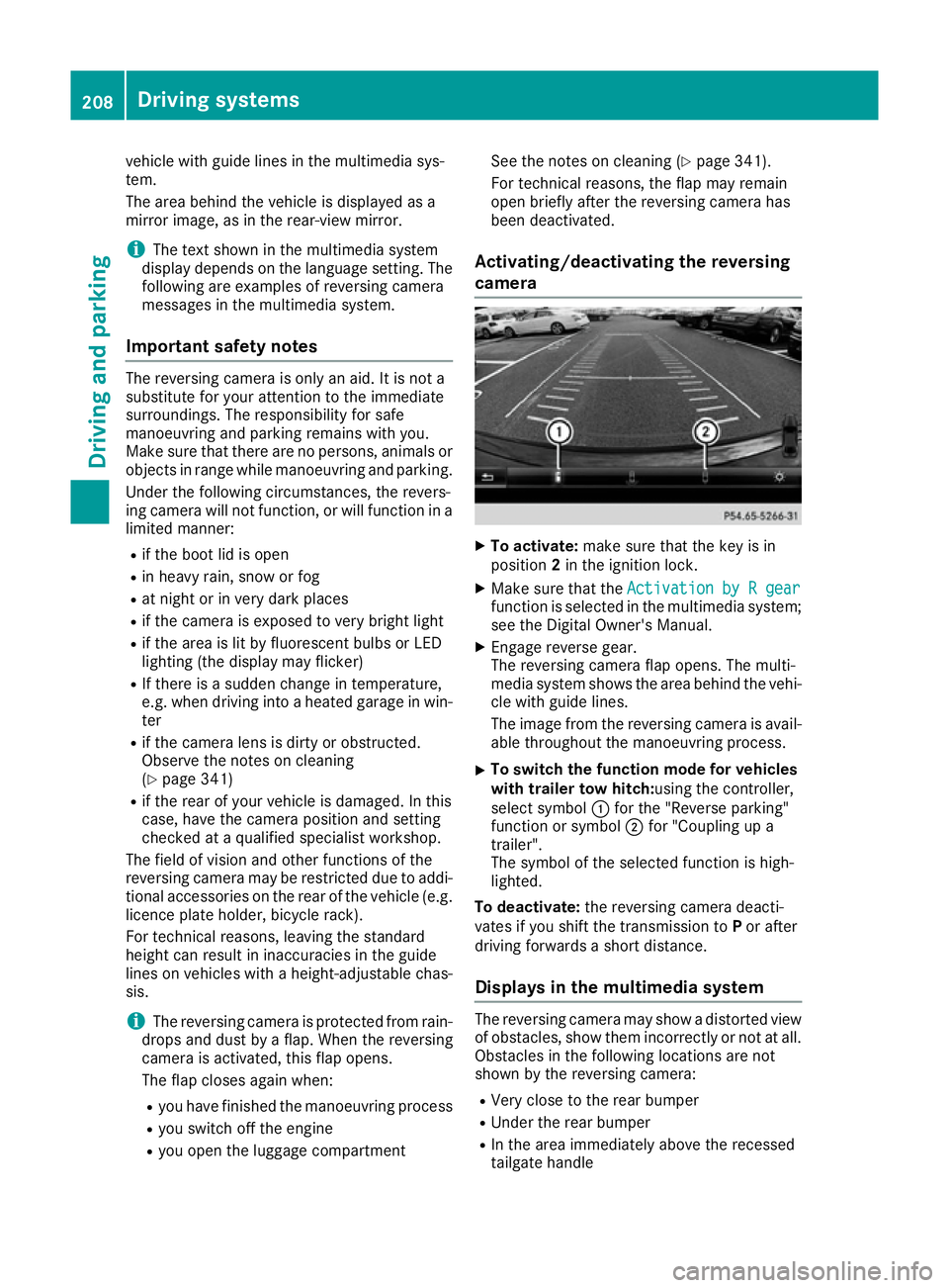
vehicle with guide lines in the multimedia sys-
tem.
The area behind the vehicle is displayed as a
mirror image, as in the rear-view mirror.
i The text shown in the multimedia system
display depends on the language setting. The following are examples of reversing camera
messages in the multimedia system.
Important safety notes The reversing camera is only an aid. It is not a
substitute for your attention to the immediate
surroundings. The responsibility for safe
manoeuvring and parking remains with you.
Make sure that there are no persons, animals or objects in range while manoeuvring and parking.
Under the following circumstances, the revers-
ing camera will not function, or will function in a limited manner:
R if the boot lid is open
R in heavy rain, snow or fog
R at night or in very dark places
R if the camera is exposed to very bright light
R if the area is lit by fluorescent bulbs or LED
lighting (the display may flicker)
R If there is a sudden change in temperature,
e.g. when driving into a heated garage in win- ter
R if the camera lens is dirty or obstructed.
Observe the notes on cleaning
(Y page 341)
R if the rear of your vehicle is damaged. In this
case, have the camera position and setting
checked at a qualified specialist workshop.
The field of vision and other functions of the
reversing camera may be restricted due to addi-
tional accessories on the rear of the vehicle (e.g. licence plate holder, bicycle rack).
For technical reasons, leaving the standard
height can result in inaccuracies in the guide
lines on vehicles with a height-adjustable chas-
sis.
i The reversing camera is protected from rain-
drops and dust by a flap. When the reversing
camera is activated, this flap opens.
The flap closes again when:
R you have finished the manoeuvring process
R you switch off the engine
R you open the luggage compartment See the notes on cleaning (Y
page 341).
For technical reasons, the flap may remain
open briefly after the reversing camera has
been deactivated.
Activating/deactivating the reversing
camera X
To activate: make sure that the key is in
position 2in the ignition lock.
X Make sure that the Activation by R gear Activation by R gear
function is selected in the multimedia system; see the Digital Owner's Manual.
X Engage reverse gear.
The reversing camera flap opens. The multi-
media system shows the area behind the vehi-
cle with guide lines.
The image from the reversing camera is avail-
able throughout the manoeuvring process.
X To switch the function mode for vehicles
with trailer tow hitch: using the controller,
select symbol :for the "Reverse parking"
function or symbol ;for "Coupling up a
trailer".
The symbol of the selected function is high-
lighted.
To deactivate: the reversing camera deacti-
vates if you shift the transmission to Por after
driving forwards a short distance.
Displays in the multimedia system The reversing camera may show a distorted view
of obstacles, show them incorrectly or not at all. Obstacles in the following locations are not
shown by the reversing camera:
R Very close to the rear bumper
R Under the rear bumper
R In the area immediately above the recessed
tailgate handle 208
Driving systemsDriving and parking
Page 216 of 397
The flap closes again when:
R you have finished the manoeuvring process
R you switch off the engine
R you open the luggage compartment
See the notes on cleaning (Y page 341).
For technical reasons, the flap may remain
open briefly after the camera has been deac- tivated.
Important safety notes The 360° camera is only an aid and may show a
distorted view of obstacles, show them incor-
rectly or not at all. The 360° camera is not a
substitute for attentive driving.
The responsibility for safe manoeuvring and
parking remains with you. Make sure that there
are no persons, animals or objects in range
while manoeuvring and parking.
You are responsible for safety at all times and
must always pay attention to your surroundings when parking and manoeuvring. This applies to
the areas behind, in front of and beside the vehi- cle. You could otherwise endanger yourself and
others.
The 360° camera will not function or will func-
tion only to a limited extent:
R If the doors are open
R If the exterior mirrors are folded in
R If the tailgate is open
R In heavy rain, snow or fog
R At night or in very dark places
R If the cameras are exposed to very bright light
R If the area is lit by fluorescent bulbs or LED
lighting (the display may flicker)
R If there is a sudden change in temperature,
e.g. when driving into a heated garage in win- ter
R If the camera lenses are dirty or covered
R If the vehicle components in which the cam-
eras are fitted are damaged. In this event,
have the camera position and setting checked
at a qualified specialist workshop
Do not use the 360° camera under such cir-
cumstances. You could otherwise injure others
or damage objects when parking the vehicle.
Guide lines are always shown at road level. In
trailer mode, the guide lines are shown at the
level of the trailer coupling. The field of vision and other functions of the
camera system may be restricted due to addi-
tional accessories on the rear of the vehicle (e.g.
licence plate holder, bicycle rack).
On vehicles with height-adjustable suspension,
due to the technical conditions, leaving the
standard height can result in the following:
R Inaccuracies in the guide lines
R Inaccuracies in the display of generated
images (top view)
Activation conditions The 360° camera image can be displayed if:
R your vehicle is equipped with a 360° camera
R the key is in position 2in the ignition lock
R the multimedia system is switched on
Activating the 360° camera X
Press the Øbutton in the centre console
for longer than two seconds.
The following appears depending on whether transmission position Dor Ris selected:
R a split screen with top view and the image
from the front camera or
R a split screen with top view and the image
from the reversing camera
or
X Press the Øbutton in the centre console.
The vehicle menu appears.
X Select 360°
360° camera camera and press 7to confirm.
The following appears depending on whether transmission position Dor Ris selected:
R a split screen with top view and the image
from the front camera or
R a split screen with top view and the image
from the reversing camera
Switching on the 360° camera using
reverse gear You can show images from the 360° camera
automatically by engaging reverse gear. Driving systems
213Driving and parking Z
Page 217 of 397
X
Make sure that the key is in position 2in the
ignition lock.
X Make sure that the Activation by R gear
Activation by R gear
function is selected in the multimedia system (see the separate operating instructions).
X To show the 360° camera image: engage
reverse gear.
The multimedia system shows the area
behind the vehicle in split-screen mode. You
see the top view of the vehicle and the image from the reversing camera.
Selecting the split-screens or 180° view Selecting split-screen view
X To switch to the line with the vehicle icons:
slide 5the controller.
X To select one of the vehicle icons: turn 3
the controller.
X To switch to 180° view 180° view:turn 3 the con-
troller to select 180° view
180° view and press7to
confirm.
i The
180°
180° view
viewoption is only available in the
following views:
R Top view with image from the reversing
camera
R Top view with image from the front camera
Displays in the multimedia system Important safety notes
The camera system may show a distorted view
of obstacles or show them incorrectly or not at
all. Obstacles in the following locations are not
shown by the system:
R Under the front and rear bumpers
R Very close to the front and rear bumpers
R In the area immediately above the recessed
tailgate handle
R Very close to the exterior mirrors
R In the transitional areas between the various
cameras in the virtual top view
! Objects not at ground level may appear to
be further away than they actually are, e.g.:
R the bumper of a parked vehicle
R the drawbar of a trailer
R the ball coupling of a trailer tow hitch R
the rear section of an HGV
R a slanted post
Use the guidelines only for orientation.
Approach objects no further than the bottom- most guideline.
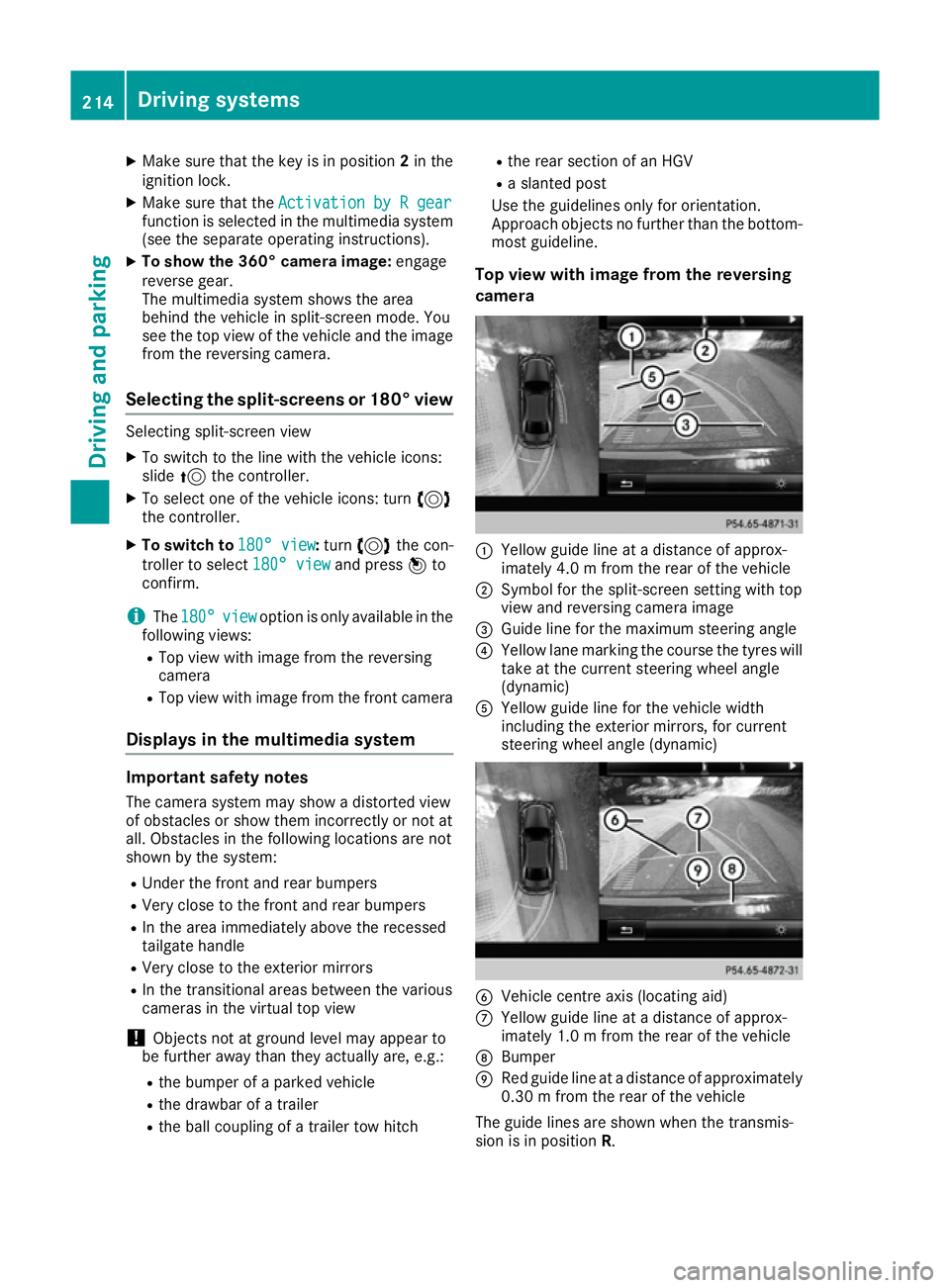
Top view with image from the reversing
camera :
Yellow guide line at a distance of approx-
imately 4.0 m from the rear of the vehicle
; Symbol for the split-screen setting with top
view and reversing camera image
= Guide line for the maximum steering angle
? Yellow lane marking the course the tyres will
take at the current steering wheel angle
(dynamic)
A Yellow guide line for the vehicle width
including the exterior mirrors, for current
steering wheel angle (dynamic) B
Vehicle centre axis (locating aid)
C Yellow guide line at a distance of approx-
imately 1.0 m from the rear of the vehicle
D Bumper
E Red guide line at a distance of approximately
0.30 m from the rear of the vehicle
The guide lines are shown when the transmis-
sion is in position R.214
Driving systemsDriving and parking
Page 236 of 397
E
Level control
F Compass with angle scale
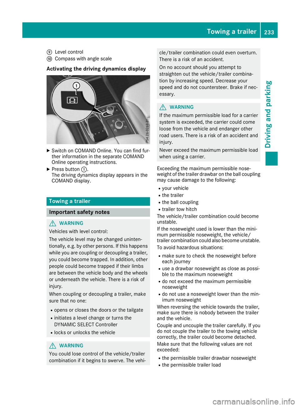
Activating the driving dynamics display X
Switch on COMAND Online. You can find fur-
ther information in the separate COMAND
Online operating instructions.
X Press button :.
The driving dynamics display appears in the
COMAND display. Towing a trailer
Important safety notes
G
WARNING
Vehicles with level control:
The vehicle level may be changed uninten-
tionally, e.g. by other persons. If this happens while you are coupling or decoupling a trailer,
you could become trapped. In addition, other
people could become trapped if their limbs
are between the vehicle body and the wheels or underneath the vehicle. There is a risk of
injury.
When coupling or decoupling a trailer, make
sure that no one:
R opens or closes the doors or the tailgate
R initiates a level change or turns the
DYNAMIC SELECT Controller
R locks or unlocks the vehicle G
WARNING
You could lose control of the vehicle/trailer
combination if it begins to swerve. The vehi- cle/trailer combination could even overturn.
There is a risk of an accident.
On no account should you attempt to
straighten out the vehicle/trailer combina-
tion by increasing speed. Decrease your
speed and do not countersteer. Brake if nec-
essary. G
WARNING
If the maximum permissible load for a carrier system is exceeded, the carrier could come
loose from the vehicle and endanger other
road users. There is a risk of an accident and injury.
Never exceed the maximum permissible load
when using a carrier.
Exceeding the maximum permissible nose-
weight of the trailer drawbar on the ball coupling
may cause damage to the following:
R your vehicle
R the trailer
R the ball coupling
R trailer tow hitch
The vehicle/trailer combination could become
unstable.
If the noseweight used is lower than the mini-
mum permissible noseweight, the vehicle/
trailer combination could also become unstable. To avoid hazardous situations:
R make sure to check the noseweight before
each journey
R use a drawbar noseweight as close as possi-
ble to the maximum noseweight
R do not exceed the maximum permissible
noseweight
R do not use a noseweight lower than the min-
imum noseweight
When reversing the vehicle towards the trailer,
make sure there is nobody between the trailer
and the vehicle.
Couple and uncouple the trailer carefully. If you do not couple the trailer to the towing vehicle
correctly, the trailer could become detached.
Make sure that the following values are not
exceeded:
R the permissible trailer drawbar noseweight
R the permissible trailer load Towing a trailer
233Driving and parking Z
Page 238 of 397
brake system and prevents the brakes from
overheating and wearing too quickly. If you need
additional braking, depress the brake pedal
repeatedly rather than continuously.
Driving tips If the trailer swings from side to side:
X Do not accelerate under any circumstances.
X Do not countersteer.
X Brake, if necessary.
R Maintain a greater distance to the vehicle in
front than when driving without a trailer.
R Avoid braking abruptly. If possible, brake gen-
tly at first to allow the trailer to run on. Then,
increase the braking force rapidly.
R The values given for gradient-climbing capa-
bilities from a standstill refer to sea level.
When driving in mountainous areas, note that
the power output of the engine, and conse-
quently the vehicle's gradient-climbing capa-
bility from a standstill, decrease with increas- ing altitude. Swivelling the ball coupling out/in
Using the switch in the driver's door G
WARNING
If the ball coupling is not engaged, the trailer
may come loose. There is a risk of an accident. Make sure that the ball coupling is securely
engaged and locked in position.
! Do not attempt to speed the up the swing-
out procedure by applying additional pressure
with your foot. The system could otherwise be
mechanically damaged.
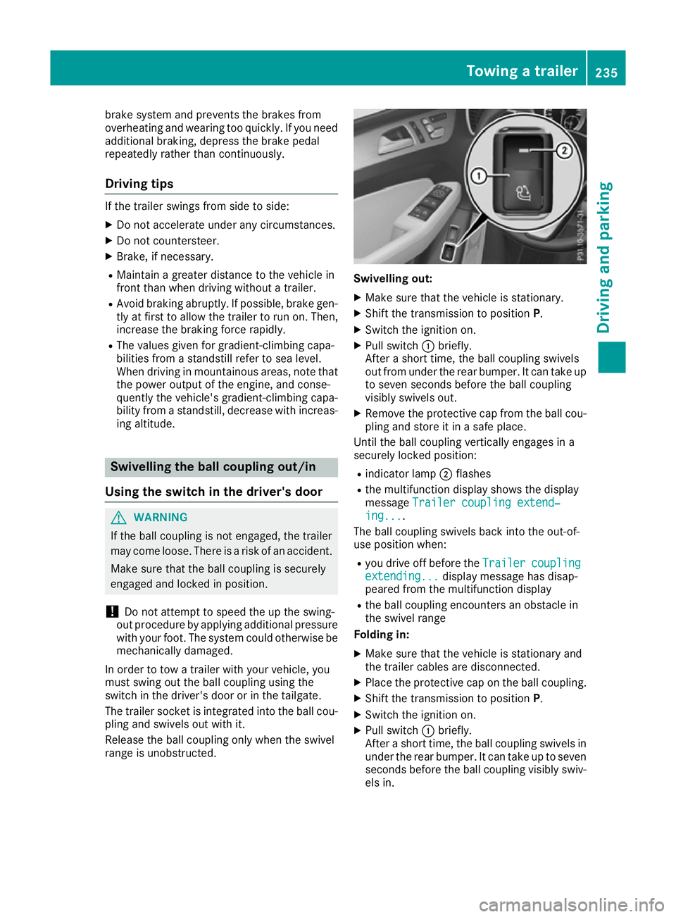
In order to tow a trailer with your vehicle, you
must swing out the ball coupling using the
switch in the driver's door or in the tailgate.
The trailer socket is integrated into the ball cou- pling and swivels out with it.
Release the ball coupling only when the swivel
range is unobstructed. Swivelling out:
X Make sure that the vehicle is stationary.
X Shift the transmission to position P.
X Switch the ignition on.
X Pull switch :briefly.
After a short time, the ball coupling swivels
out from under the rear bumper. It can take up to seven seconds before the ball coupling
visibly swivels out.
X Remove the protective cap from the ball cou-
pling and store it in a safe place.
Until the ball coupling vertically engages in a
securely locked position:
R indicator lamp ;flashes
R the multifunction display shows the display
message Trailer coupling extend‐ Trailer coupling extend‐
ing...
ing... .
The ball coupling swivels back into the out-of-
use position when:
R you drive off before the Trailer
Trailercoupling
coupling
extending...
extending... display message has disap-
peared from the multifunction display
R the ball coupling encounters an obstacle in
the swivel range
Folding in:
X Make sure that the vehicle is stationary and
the trailer cables are disconnected.
X Place the protective cap on the ball coupling.
X Shift the transmission to position P.
X Switch the ignition on.
X Pull switch :briefly.
After a short time, the ball coupling swivels in under the rear bumper. It can take up to seven
seconds before the ball coupling visibly swiv- els in. Towing a trailer
235Driving and parking Z
Page 239 of 397
Until the ball coupling engages in a securely
locked position under the bumper:
R indicator lamp ;flashes
R the multifunction display shows the display
message Trailer coupling extend‐
Trailer coupling extend‐
ing...
ing...
The ball coupling swivels back into the out-of-
use position when:
R you drive off before the Trailer
Trailer coupling
coupling
extending...
extending... display message has disap-
peared from the multifunction display
R the ball coupling encounters an obstacle in
the swivel range
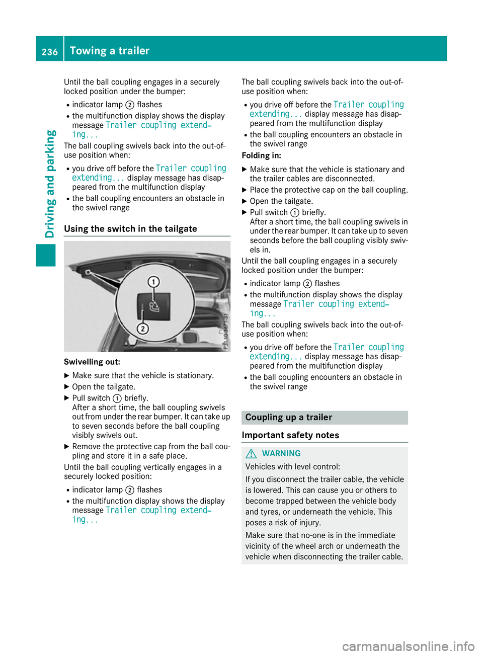
Using the switch in the tailgate Swivelling out:
X Make sure that the vehicle is stationary.
X Open the tailgate.
X Pull switch :briefly.
After a short time, the ball coupling swivels
out from under the rear bumper. It can take up to seven seconds before the ball coupling
visibly swivels out.
X Remove the protective cap from the ball cou-
pling and store it in a safe place.
Until the ball coupling vertically engages in a
securely locked position:
R indicator lamp ;flashes
R the multifunction display shows the display
message Trailer coupling extend‐
Trailer coupling extend‐
ing... ing... The ball coupling swivels back into the out-of-
use position when:
R you drive off before the Trailer
Trailercoupling
coupling
extending...
extending... display message has disap-
peared from the multifunction display
R the ball coupling encounters an obstacle in
the swivel range
Folding in:
X Make sure that the vehicle is stationary and
the trailer cables are disconnected.
X Place the protective cap on the ball coupling.
X Open the tailgate.
X Pull switch :briefly.
After a short time, the ball coupling swivels in under the rear bumper. It can take up to sevenseconds before the ball coupling visibly swiv-
els in.
Until the ball coupling engages in a securely
locked position under the bumper:
R indicator lamp ;flashes
R the multifunction display shows the display
message Trailer coupling extend‐ Trailer coupling extend‐
ing...
ing...
The ball coupling swivels back into the out-of-
use position when:
R you drive off before the Trailer
Trailercoupling
coupling
extending...
extending... display message has disap-
peared from the multifunction display
R the ball coupling encounters an obstacle in
the swivel range Coupling up a trailer
Important safety notes G
WARNING
Vehicles with level control:
If you disconnect the trailer cable, the vehicle is lowered. This can cause you or others to
become trapped between the vehicle body
and tyres, or underneath the vehicle. This
poses a risk of injury.
Make sure that no-one is in the immediate
vicinity of the wheel arch or underneath the
vehicle when disconnecting the trailer cable. 236
Towing a trailerDriving and parking
Page 240 of 397
Vehicles with the AIRMATIC package
!
Before beginning the journey, make sure
that the trailer support wheel is completely
raised. Otherwise, the trailer or the vehicle
could be damaged by the lowered trailer sup- port wheel during the journey.
X Shift the transmission to position P.
X Apply the electric parking brake.
X Start the engine.
X Vehicles with the Off-Road Engineering
package:
set the vehicle level to normal level
(Y page 192).
X Vehicles without the Off-Road Engineer-
ing package: select theComfortdrive pro-
gram using the DYNAMIC SELECT controller
(Y page 197).
X Switch off the engine.
X Close the doors and tailgate.
X Position the trailer horizontally behind the
vehicle.
X Couple up the trailer.
X Establish the electrical connection between
the vehicle and the trailer.
X Check that the trailer lighting system is work-
ing.
X Push the combination switch upwards and
downwards and check whether the corre-
sponding turn signal indicator on the trailer is
flashing.
A connected trailer is only detected when the
electrical connection is established correctly
and when the lighting system is working prop-
erly. The function of other systems also depends on this, for example:
R ESP ®
R Parking Assist PARKTRONIC
R Parking Pilot
R Active Blind Spot Assist
R Active Lane Keeping Assist
i Vehicles with the AIRMATIC package:
if
you couple up a trailer, the vehicle initially
remains at the selected level of the drive pro- gram set. Observe the following when cou-
pling up a trailer:
R If the normal level was not selected previ-
ously, the vehicle automatically adopts the normal level starting from a speed of 30 km/h. Even at higher speeds, it does not
drop below the normal level.
R Vehicle levels below the normal level are
not available.
R The raised level is available up to a speed of
30 km/h.
R This also applies when using accessories
that are plugged into the socket of the
trailer tow hitch (e.g. a bicycle rack).
R Before driving with a trailer, please observe
the information on the trailer support
wheel. Uncoupling a trailer
Important safety notes G
WARNING
If you uncouple a trailer with an engaged over- run brake, you could trap your hand between
the vehicle and the trailer drawbar. This poses a risk of injury.
Do not uncouple a trailer with an engaged
overrun brake. G
WARNING
Vehicles with level control:
If you disconnect the trailer cable, the vehicle is lowered. This can cause you or others to
become trapped between the vehicle body
and tyres, or underneath the vehicle. This
poses a risk of injury.
Make sure that no-one is in the immediate
vicinity of the wheel arch or underneath the
vehicle when disconnecting the trailer cable.
! Do not disconnect a trailer with an engaged
overrun brake. Otherwise, your vehicle could
be damaged by the rebounding of the overrun
brake.
! Remove the adapter cable before folding in
the ball coupling. You could otherwise dam-
age the rear bumper and the adapter cable.
Vehicles with the AIRMATIC package X
Shift the transmission to position P.
X Apply the electric parking brake. Towing a trailer
237Driving and parking Z
Page 241 of 397
X
Start the engine.
X Close the doors and tailgate.
X Secure the trailer against rolling away.
X Remove the trailer cable and decouple the
trailer.
X Switch off the engine. Trailer power supply
! You can connect accessories with a power
rating of up to 180 W to the permanent power
supply and with a power rating of up to 180 W to the power supply that is switched on via the ignition lock.
The trailer battery may not be charged from
the power supply.
When it leaves the factory, your vehicle's trailer
socket is equipped with a permanent power
supply and a power supply that is switched on
via the ignition lock.
The permanent power supply is supplied via
trailer socket pin 9.
The power supply that is switched on via the
ignition lock is supplied via trailer socket pin 10.
The trailer's permanent power supply is
switched off in the event of low vehicle supply
voltage and after six hours at the latest.
You can find more information about fitting the
trailer electrics at a qualified specialist work-
shop.
X To switch the connected power supply on
or off: turn the key to position 2or0respec-
tively (Y page 148). Failure check for LEDs
If LED lamps are fitted in the trailer, a malfunc-
tion message may appear in the multifunction
display even if there is no fault. The reason for
the error message may be that the current has
fallen below the minimum of 50 mA. To ensure reliable indication of the failure, each
LED chain in the trailer lighting must be guaran-
teed a minimum current of 50 mA. Trailer with 7-pin connector
General notes Trailer with 7-pin connector:
you can connect
to the 13-pin socket on the ball coupling using
an adapter or, if necessary, an adapter cable.
Both can be obtained at a qualified specialist
workshop.
Fitting the adapter !
Make sure that there is sufficient cable play
so that the cable cannot become detached
when cornering.
! Remove the adapter cable before folding in
the ball coupling. You could otherwise dam-
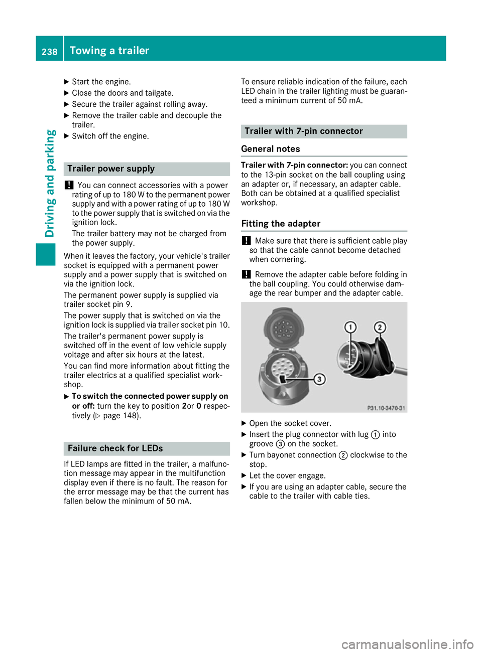
age the rear bumper and the adapter cable. X
Open the socket cover.
X Insert the plug connector with lug :into
groove =on the socket.
X Turn bayonet connection ;clockwise to the
stop.
X Let the cover engage.
X If you are using an adapter cable, secure the
cable to the trailer with cable ties. 238
Towing a trailerDriving and parking