2016 MERCEDES-BENZ GLS SUV clock
[x] Cancel search: clockPage 196 of 397

Always select as low a vehicle level as possi-
ble and adjust your driving style accordingly. G
WARNING
When driving with a lowered or raised chassis frame, the driving and braking characteristics
may be seriously affected. A raised chassis
frame may also exceed the permissible vehi-
cle height. There is a risk of an accident.
Set the driving level before pulling away. G
WARNING
Due to the high centre of gravity, the vehicle
may start to skid and overturn in the event of abrupt steering manoeuvres and/or when the
vehicle's speed is not adapted to the road
conditions. There is a risk of an accident.
Always adapt your speed and driving style to
the vehicle's driving characteristics and to the prevailing road and weather conditions.
! When driving on extremely rough terrain,
select a high vehicle level in good time. Make
sure there is always sufficient ground clear-
ance. You will otherwise damage the vehicle.
R SUVs overturn considerably more often than
other vehicle types.
If this vehicle is not driven in a safe manner, it can lead to an accident, to the vehicle over-
turning as well as serious or even fatal inju-
ries.
R In the event of an accident with the vehicle
overturning, passengers who are not wearing
their seat belt are considerably more likely to die than passengers wearing their seat belt.
You and all vehicle occupants should always
wear your seat belts.
Basic settings The extent to which the vehicle is raised or low-
ered depends on the basic setting selected.
Select:
R the Comfort orSport drive program for driv-
ing on normal roads
R the Offroad drive program for driving on eas-
ily negotiable off-road terrain
R the Offroad Plus drive program for off-road
driving R
Offroad level 1 for driving on easily negotiable
off-road terrain
R Offroad level 2 for driving on normal off-road
terrain
R Offroad level 3 for freeing the vehicle from
especially difficult off-road terrain at low
speeds
The individual vehicle levels differ from the nor- mal level as follows:
R –15 mm in the Sportdrive program
R +/–0 mm in the Comfortdrive program
R + 30 mm in the Offroaddrive program
R + 60 mm in the Offroad Plusdrive program
R + 30 mm in offroad level 1
R + 60 mm in offroad level 2
R + 90 mm in offroad level 3
Setting the vehicle level !
Make sure there is enough ground clear-
ance when the vehicle is being lowered. It
could otherwise hit the ground, damaging the
underbody. Setting the vehicle level using the selector
wheel
X Start the engine.
X Press selector wheel :.
Selector wheel :extends.
X To raise the vehicle: turn selector wheel :
clockwise ;.
The vehicle is raised.
X To lower the vehicle: turn selector wheel :
anti-clockwise ?.
The vehicle is lowered.
During the adjustment, the Lowering
Lowering orVehi‐ Vehi‐
cle
cle rising
rising message appears in the multifunc-
tion display. Driving systems
193Driving and parking Z
Page 197 of 397

If you press the
%ora button on the
multifunction steering wheel, the message will
disappear. Once normal level has been reached,
all indicator lamps =go out.
The vehicle automatically selects normal level if
you:
R drive at speeds above 115 km/h or
R drive at speeds between 100 km/h and
115 km/h for approximately 20 seconds
The vehicle is lowered to low level if you are
travelling at higher speeds.
Normal level Setting the vehicle to normal level
X Start the engine.
X Press selector wheel :.
Selector wheel :extends.
X To lower the vehicle: turn selector wheel :
anti-clockwise ?.
The vehicle is lowered.
If one or more indicator lamps =are on:
X Turn selector wheel :anti-clockwise ?
until all indicator lamps =that are lit start to
flash.
The vehicle is lowered to normal level. As
soon as the next lowest level is reached, the
indicator lamp stops flashing and goes out.
Offroad levels General notes
Only select an offroad level if this is appropriate for road conditions. Otherwise, fuel consump-
tion may increase and handling performance
may be affected. You can select the following:
R Offroad level 1 at speeds up to 100 km/h
R Offroad level 2 at speeds up to 65 km/h
R Offroad level 3 at speeds up to 20 km/h
If you select an offroad level when driving at too
high a speed, the Please reduce speed Please reduce speed mes-
sage appears in the multifunction display.
Offroad level 3 is only suitable for driving on
extremely difficult off-road terrain under partic- ularly rough conditions.
R Adjust your driving style to the altered han-
dling characteristics.
R Do not drive faster than 20 km/h. Indicator lamps
=for the desired offroad level
flash:
R the lower indicator lamp flashes, offroad
level 1 is selected
R the lower and centre indicator lamps flash,
offroad level 2 is selected
R all three indicator lamps flash, offroad level 3
is selected
The vehicle is being adjusted to the offroad level
selected. As soon as an offroad level is reached,
the corresponding indicator lamp stops flashing and lights up constantly.
Raising the vehicle
Setting the vehicle level using the selector
wheel
X To raise the vehicle: turn selector wheel :
clockwise ;.
The vehicle is raised to offroad level 1 by
30 mm compared to the normal level.
During the adjustment, the Vehicle rising Vehicle rising
message, for example, appears in the multifunc-
tion display. 194
Driving systemsDriving and parking
Page 241 of 397
X
Start the engine.
X Close the doors and tailgate.
X Secure the trailer against rolling away.
X Remove the trailer cable and decouple the
trailer.
X Switch off the engine. Trailer power supply
! You can connect accessories with a power
rating of up to 180 W to the permanent power
supply and with a power rating of up to 180 W to the power supply that is switched on via the ignition lock.
The trailer battery may not be charged from
the power supply.
When it leaves the factory, your vehicle's trailer
socket is equipped with a permanent power
supply and a power supply that is switched on
via the ignition lock.
The permanent power supply is supplied via
trailer socket pin 9.
The power supply that is switched on via the
ignition lock is supplied via trailer socket pin 10.
The trailer's permanent power supply is
switched off in the event of low vehicle supply
voltage and after six hours at the latest.
You can find more information about fitting the
trailer electrics at a qualified specialist work-
shop.
X To switch the connected power supply on
or off: turn the key to position 2or0respec-
tively (Y page 148). Failure check for LEDs
If LED lamps are fitted in the trailer, a malfunc-
tion message may appear in the multifunction
display even if there is no fault. The reason for
the error message may be that the current has
fallen below the minimum of 50 mA. To ensure reliable indication of the failure, each
LED chain in the trailer lighting must be guaran-
teed a minimum current of 50 mA. Trailer with 7-pin connector
General notes Trailer with 7-pin connector:
you can connect
to the 13-pin socket on the ball coupling using
an adapter or, if necessary, an adapter cable.
Both can be obtained at a qualified specialist
workshop.
Fitting the adapter !
Make sure that there is sufficient cable play
so that the cable cannot become detached
when cornering.
! Remove the adapter cable before folding in
the ball coupling. You could otherwise dam-
age the rear bumper and the adapter cable. X
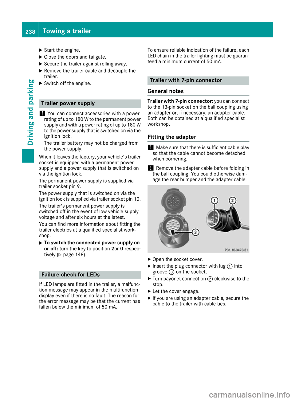
Open the socket cover.
X Insert the plug connector with lug :into
groove =on the socket.
X Turn bayonet connection ;clockwise to the
stop.
X Let the cover engage.
X If you are using an adapter cable, secure the
cable to the trailer with cable ties. 238
Towing a trailerDriving and parking
Page 244 of 397
Important safety notes
G
WARNING
Operating the integrated information systems and communications equipment in the vehicle
while driving will distract you from traffic con-
ditions. You could then lose control of the
vehicle. There is a risk of an accident.
Only operate these devices if road traffic con-
ditions permit. If you are unsure about the
surrounding conditions, pull over to a safe
location and make entries only while the vehi-
cle is stationary.
You must observe the legal requirements for the country in which you are currently driving whenoperating the on-board computer. G
WARNING
If the instrument cluster has failed or mal-
functioned, you may not recognise function
restrictions relevant to safety. The operating
safety of your vehicle may be impaired. There is a risk of an accident.
Drive on carefully. Have the vehicle checked
at a qualified specialist workshop immedi-
ately.
If the operating safety of your vehicle is
impaired, park the vehicle safely as soon as pos-
sible. Contact a qualified specialist workshop.
The on-board computer shows only messages or warnings from certain systems on the multi-
function display. You should therefore make
sure your vehicle is operating safely at all times.
For an overview, see the instrument cluster illus-
tration (Y page 35). Displays and operation
Instrument cluster lighting
The lighting in the instrument cluster, in the dis-
plays and the controls in the vehicle interior can be adjusted using the brightness control knob.
The brightness control knob is located on the
bottom left of the instrument cluster
(Y page 35). X
Turn the brightness control knob clockwise or
anti-clockwise.
If you turn the light switch to Ã,Tor
L, the brightness is dependent upon the
brightness of the ambient light.
i The light sensor in the instrument cluster
automatically controls the brightness of the
multifunction display.
In daylight, the displays in the instrument
cluster are not illuminated. Speedometer with segments
The segments in the speedometer indicate
which speed range is available.
R Cruise control activated (Y page 180):
The segments light up from the stored speed to the maximum speed.
R Variable speed limiter is activated
(Y page 182):
The segments light up from the start of the
scale to the selected speed limitation.
R Distance Pilot DISTRONIC is activated
(Y page 184):
One or two segments in the stored speed
range light up.
R Distance Pilot DISTRONIC detects a vehicle in
front moving more slowly than the stored
speed:
The segments between the speed of the vehi- cle in front and the stored speed light up. Rev counter
! Do not drive in the overrevving range. Doing
so will damage the engine.
The red band in the rev counter indicates the
engine's overrevving range.
The fuel supply is interrupted to protect the
engine when the red band is reached. Outside temperature display
You should pay special attention to road condi-
tions when temperatures are around freezing
point. Displays and operation
241On-board computer and displays Z
Page 338 of 397
The following cause engine failure or damage
to the exhaust system:
R Use of engine oils and oil filters that have
not been expressly approved for the service
system
R Replacement of engine oil and oil filter after
the replacement interval specified by the
service system has expired
R Use of engine oil additives
! Do not add too much oil. Topping up with too
much engine oil can result in damage to the
engine or to the catalytic converter. Have
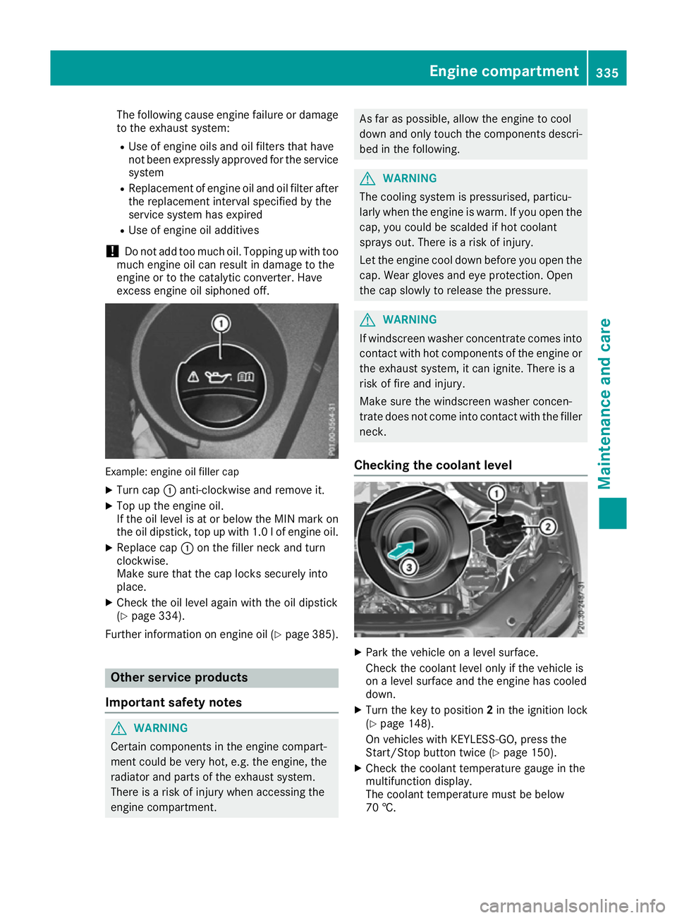
excess engine oil siphoned off. Example: engine oil filler cap
X Turn cap :anti-clockwise and remove it.
X Top up the engine oil.
If the oil level is at or below the MIN mark on
the oil dipstick, top up with 1.0 lof engine oil.
X Replace cap :on the filler neck and turn
clockwise.
Make sure that the cap locks securely into
place.
X Check the oil level again with the oil dipstick
(Y page 334).
Further information on engine oil (Y page 385).Other service products
Important safety notes G
WARNING
Certain components in the engine compart-
ment could be very hot, e.g. the engine, the
radiator and parts of the exhaust system.
There is a risk of injury when accessing the
engine compartment. As far as possible, allow the engine to cool
down and only touch the components descri-
bed in the following. G
WARNING
The cooling system is pressurised, particu-
larly when the engine is warm. If you open the cap, you could be scalded if hot coolant
sprays out. There is a risk of injury.
Let the engine cool down before you open the
cap. Wear gloves and eye protection. Open
the cap slowly to release the pressure. G
WARNING
If windscreen washer concentrate comes into contact with hot components of the engine or
the exhaust system, it can ignite. There is a
risk of fire and injury.
Make sure the windscreen washer concen-
trate does not come into contact with the filler neck.
Checking the coolant level X
Park the vehicle on a level surface.
Check the coolant level only if the vehicle is
on a level surface and the engine has cooled
down.
X Turn the key to position 2in the ignition lock
(Y page 148).
On vehicles with KEYLESS-GO, press the
Start/Stop button twice (Y page 150).
X Check the coolant temperature gauge in the
multifunction display.
The coolant temperature must be below
70 †. Engine compartment
335Maintenance and care Z
Page 339 of 397
X
Turn the key to position 0in the ignition lock
(Y page 148).
X On vehicles with KEYLESS-GO, press the
Start/Stop button (Y page 150).
X Press the Start/Stop button (Y page 150).
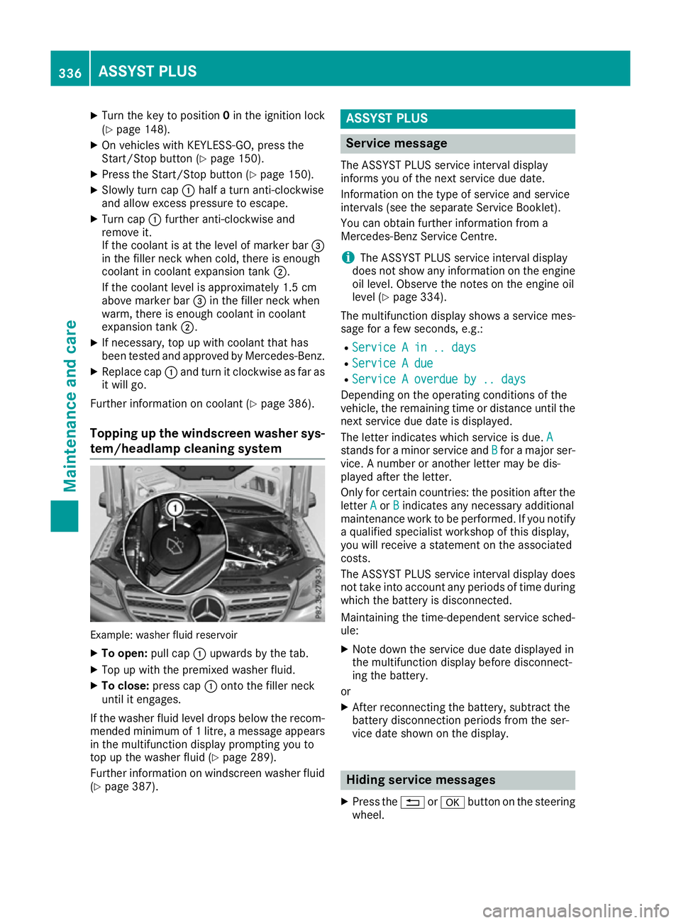
X Slowly turn cap :half a turn anti-clockwise
and allow excess pressure to escape.
X Turn cap :further anti-clockwise and
remove it.
If the coolant is at the level of marker bar =
in the filler neck when cold, there is enough
coolant in coolant expansion tank ;.
If the coolant level is approximately 1.5 cm
above marker bar =in the filler neck when
warm, there is enough coolant in coolant
expansion tank ;.
X If necessary, top up with coolant that has
been tested and approved by Mercedes-Benz.
X Replace cap :and turn it clockwise as far as
it will go.
Further information on coolant (Y page 386).
Topping up the windscreen washer sys- tem/headlamp cleaning system Example: washer fluid reservoir
X To open: pull cap:upwards by the tab.
X Top up with the premixed washer fluid.
X To close: press cap :onto the filler neck
until it engages.
If the washer fluid level drops below the recom- mended minimum of 1 litre, a message appears in the multifunction display prompting you to
top up the washer fluid (Y page 289).
Further information on windscreen washer fluid
(Y page 387). ASSYST PLUS
Service message
The ASSYST PLUS service interval display
informs you of the next service due date.
Information on the type of service and service
intervals (see the separate Service Booklet).
You can obtain further information from a
Mercedes-Benz Service Centre.
i The ASSYST PLUS service interval display
does not show any information on the engine oil level. Observe the notes on the engine oil
level (Y page 334).
The multifunction display shows a service mes-
sage for a few seconds, e.g.:
R Service A in .. days Service A in .. days
R Service A due
Service A due
R Service A overdue by .. days
Service A overdue by .. days
Depending on the operating conditions of the
vehicle, the remaining time or distance until the
next service due date is displayed.
The letter indicates which service is due. A A
stands for a minor service and B
Bfor a major ser-
vice. A number or another letter may be dis-
played after the letter.
Only for certain countries: the position after the letter A
A or B
Bindicates any necessary additional
maintenance work to be performed. If you notify
a qualified specialist workshop of this display,
you will receive a statement on the associated
costs.
The ASSYST PLUS service interval display does
not take into account any periods of time during which the battery is disconnected.
Maintaining the time-dependent service sched-
ule:
X Note down the service due date displayed in
the multifunction display before disconnect-
ing the battery.
or
X After reconnecting the battery, subtract the
battery disconnection periods from the ser-
vice date shown on the display. Hiding service messages
X Press the %ora button on the steering
wheel. 336
ASSYST PLUSMaintenance and care
Page 356 of 397

occupants from suffering acid burns should the
battery be damaged in the event of an accident.
In order for the battery to achieve the maximum possible service life, it must always be suffi-
ciently charged.
Like other batteries, the vehicle battery may
discharge over time if you do not use the vehicle. In such cases, have the battery disconnected ata qualified specialist workshop. You can also
charge the battery with a charger recommended
by Mercedes-Benz. For more information,
please contact a qualified specialist workshop.
Have the battery charge checked more fre-
quently if you use the vehicle mainly for short
trips or if you leave it standing idle for a lengthy period. Consult a qualified specialist workshop
if you wish to leave your vehicle parked up for a
long period of time.
When you park the vehicle, remove the key if you do not require any electrical consumers. The
vehicle will then use very little energy, thus con- serving battery power.
If the power supply has been interrupted, e.g. if the battery was discharged, you will have to:
R set the clock (see the Digital Owner's Manual)
On vehicles with a multimedia system and
navigation system, the clock is set automati-
cally.
R reset the function for folding the exterior mir-
rors in/out automatically, by folding the mir-
rors out once (Y page 117). Charging the 12 V battery
G
WARNING
During charging and jump-starting, explosive
gases can escape from the battery. There is a risk of an explosion.
Particularly avoid fire, naked flames, creating
sparks and smoking. Ensure there is sufficient
ventilation while charging and jump-starting.
Do not lean over a battery. G
WARNING
Battery acid is caustic. There is a risk of injury. Avoid contact with the skin, eyes or clothing.
Do not breathe in any battery gases. Do not lean over the battery. Keep the batteries out
of the reach of children. Immediately rinse off
battery acid thoroughly with plenty of clean
water and seek medical attention at once. G
WARNING
A discharged battery can freeze at tempera-
tures below freezing point. When jump-start-
ing the vehicle or charging the battery, gases can escape from the battery. There is a risk of
an explosion.
Allow the frozen battery to thaw out before
charging it or jump-starting.
! Only use battery chargers with a maximum
charging voltage of 14.8 V.
! Only charge the battery using the jump-start
connection point.
The jump-starting connection point is in the
engine compartment (Y page 354).
X Open the bonnet.
X Connect the battery charger to the positive
terminal and earth point in the same order as
when connecting the donor battery in the
jump-starting procedure (Y page 354).
Keep away from fire and naked flames. Do not
lean over the battery. Never charge the battery
if it is still fitted to the vehicle, unless you are
using a battery charger that has been tested and approved by Mercedes-Benz. A battery charger
unit specially adapted for Mercedes-Benz vehi-
cles and tested and approved by Mercedes-
Benz is available as an accessory. This device
permits charging of the battery while it is instal-
led. Contact a Mercedes-Benz Service Centre
for information and availability. Read the battery charger's operating instructions before charg-
ing the battery.
If the indicator/warning lamps do not light up at
low temperatures, it is very likely that the dis-
charged battery has frozen. In this case you may
neither jump-start the vehicle nor charge the
battery. The service life of a battery that has
been thawed may be reduced. The starting char-
acteristics may be impaired, especially at low
temperatures. Have the thawed battery
checked at a qualified specialist workshop. Battery (vehicle)
353Breakdown assistance Z
Page 360 of 397
tance a distance so that the tow rope does
not sag.
R Do not use steel cables or chains to tow
your vehicle. You could otherwise damage
the vehicle.
! Do not use the trailer tow hitch for recovery
or towing. Do not use the towing eye for
recovery. This could damage the vehicle. If in doubt, have the vehicle recovered using a
crane.
! When towing, pull away slowly and
smoothly. Pull the towed vehicle as straight as possible and not at an acute angle. If the trac-
tive power is too high, the vehicles could be
damaged.
When towing, it is preferable to use a rigid tow- ing bar as opposed to a tow rope. A rigid towing
bar helps to keep the tractive power low.
! To tow vehicles with KEYLESS-GO, use the
key instead of the Start/Stop button. The
automatic transmission may otherwise
switch to position Pwhen you open the driv-
er's or front-passenger door which could
damage the transmission.
! Vehicles with differential locks: make sure
the differential locks are in automatic mode.
When towing, the differential locks must not
be switched on. The transmission may other- wise be damaged.
! You may tow the vehicle for a maximum of
50km. A towing speed of 50 km/h must not
be exceeded.
For towing distances over 50 km, the entire
vehicle must be lifted up and transported.
Observe the legal requirements for the relevant countries when towing.
It is better to have the vehicle transported than
to have it towed.
If the vehicle has suffered transmission damage, have it transported on a transporter or trailer.
The automatic transmission must be in position
N when the vehicle is being towed.
The battery must be connected and charged.
Otherwise, you:
R cannot turn the key to position 2in the igni-
tion lock
R cannot release the electric parking brake
R cannot shift the automatic transmission to
position N Deactivate the automatic locking feature before
towing the vehicle (Y page 253). You could oth-
erwise be locked out when pushing or towing
the vehicle.
Deactivate tow-away protection before the vehi-
cle is towed away (Y page 79). Fitting/removing the towing eye
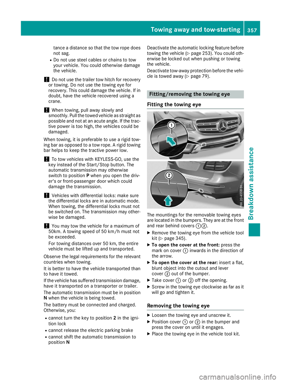
Fitting the towing eye The mountings for the removable towing eyes
are located in the bumpers. They are at the front and rear behind covers :;.
X Remove the towing eye from the vehicle tool
kit (Y page 345).
X To open the cover at the front: press the
mark on cover :inwards in the direction of
the arrow.
X To open the cover at the rear: insert a flat,
blunt object into the cutout and lever
cover ;out of the bumper.
X Take cover :or; off the opening.
X Screw in the towing eye clockwise as far as it
will go and tighten it.
Removing the towing eye X
Loosen the towing eye and unscrew it.
X Position cover :or; in the bumper and
press the cover on until it engages.
X Place the towing eye in the vehicle tool kit. Towing away and tow-starting
357Breakdown assistance Z