2016 MERCEDES-BENZ GLE-Class Important safety notes
[x] Cancel search: Important safety notesPage 336 of 450
Only use the cargo tie down rings when secur-
ing a load.
Observe the following notes on securing loads:
RSecure the load using the cargo tie-down
rings.
RDistribute the load on the cargo tie-down
rings evenly.
RDo not use elastic straps or nets to secure a
load, as these are only intended as an anti-slip
protection for light loads.
RDo not route tie-downs across sharp edges or
corners.
RPad sharp edges for protection.
Cargo compartment
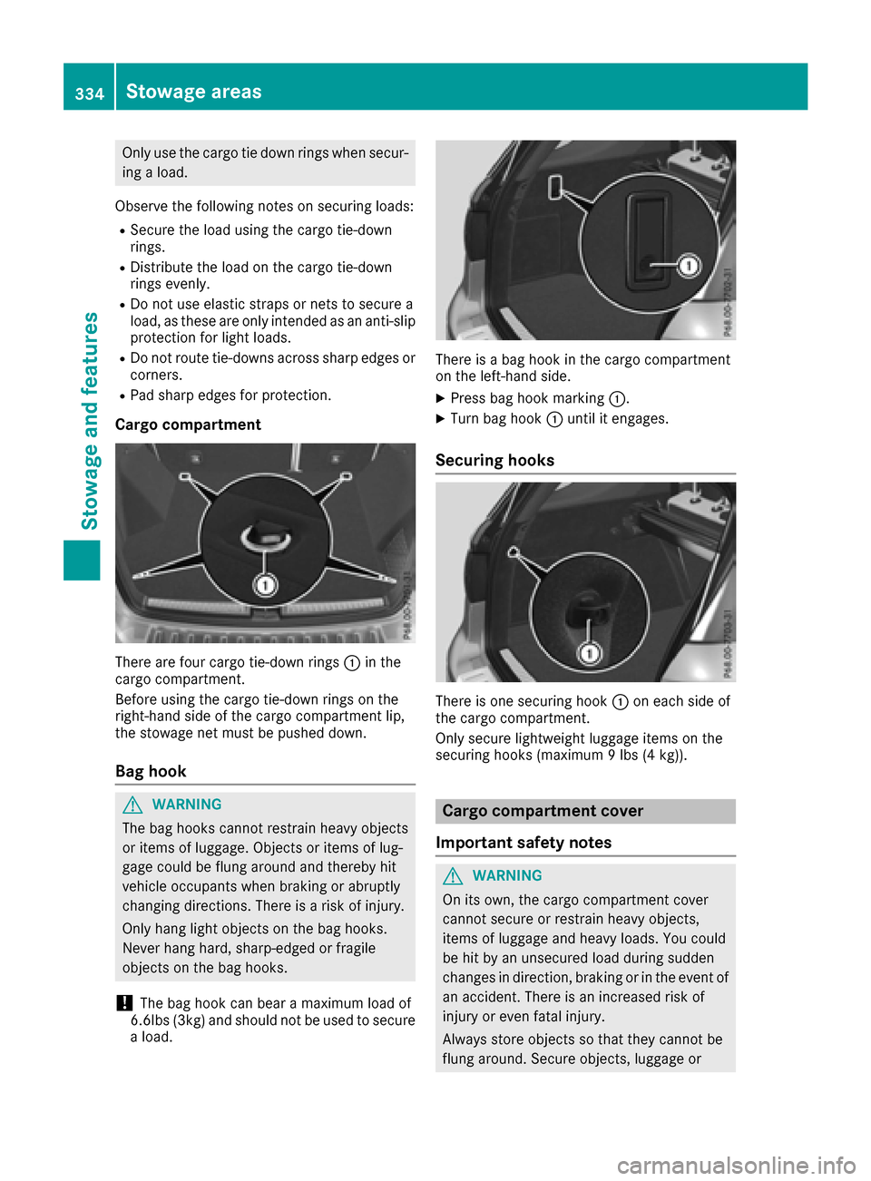
There are four cargo tie-down rings :in the
cargo compartment.
Before using the cargo tie-down rings on the
right-hand side of the cargo compartment lip,
the stowage net must be pushed down.
Bag hook
GWARNING
The bag hooks cannot restrain heavy objects
or items of luggage. Objects or items of lug-
gage could be flung around and thereby hit
vehicle occupants when braking or abruptly
changing directions. There is a risk of injury.
Only hang light objects on the bag hooks.
Never hang hard, sharp-edged or fragile
objects on the bag hooks.
!The bag hook can bear a maximum load of
6.6lbs (3kg) and should not be used to secure
a load.
There is a bag hook in the cargo compartment
on the left-hand side.
XPress bag hook marking :.
XTurn bag hook:until it engages.
Securing hooks
There is one securing hook :on each side of
the cargo compartment.
Only secure lightweight luggage items on the
securing hooks (maximum 9 lbs (4 kg)).
Cargo compartment cover
Important safety notes
GWARNING
On its own, the cargo compartment cover
cannot secure or restrain heavy objects,
items of luggage and heavy loads. You could
be hit by an unsecured load during sudden
changes in direction, braking or in the event of
an accident. There is an increased risk of
injury or even fatal injury.
Always store objects so that they cannot be
flung around. Secure objects, luggage or
334Stowage areas
Stowage and features
Page 338 of 450
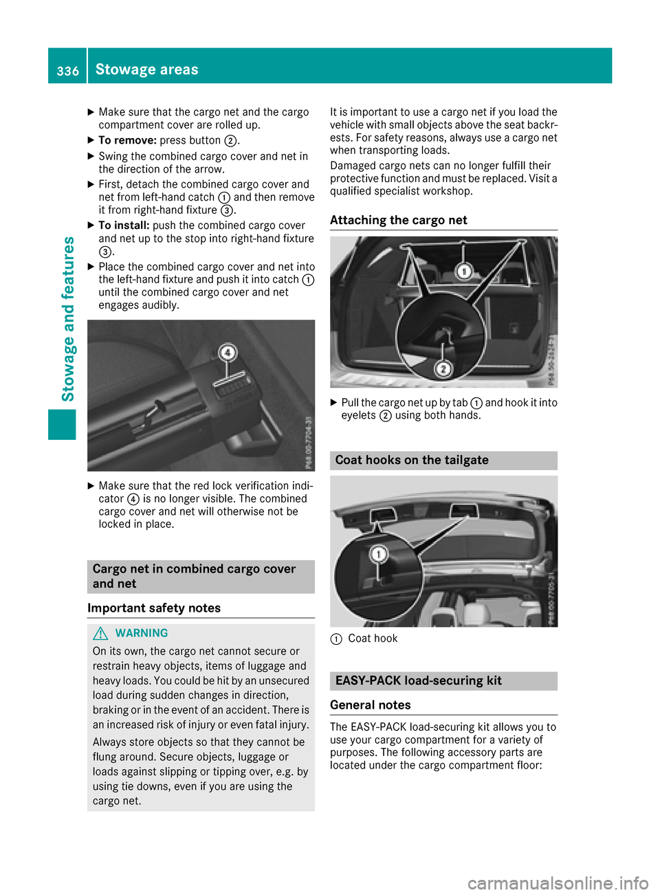
XMake sure that the cargo net and the cargo
compartment cover are rolled up.
XTo remove:press button ;.
XSwing the combined cargo cover and net in
the direction of the arrow.
XFirst, detach the combined cargo cover and
net from left-hand catch :and then remove
it from right-hand fixture =.
XTo install:push the combined cargo cover
and net up to the stop into right-hand fixture
=.
XPlace the combined cargo cover and net into
the left-hand fixture and push it into catch :
until the combined cargo cover and net
engages audibly.
XMake sure that the red lock verification indi-
cator ?is no longer visible. The combined
cargo cover and net will otherwise not be
locked in place.
Cargo net in combined cargo cover
and net
Important safety notes
GWARNING
On its own, the cargo net cannot secure or
restrain heavy objects, items of luggage and
heavy loads. You could be hit by an unsecured
load during sudden changes in direction,
braking or in the event of an accident. There is
an increased risk of injury or even fatal injury.
Always store objects so that they cannot be
flung around. Secure objects, luggage or
loads against slipping or tipping over, e.g. by
using tie downs, even if you are using the
cargo net. It is important to use a cargo net if you load the
vehicle with small objects above the seat backr-
ests. For safety reasons, always use a cargo net
when transporting loads.
Damaged cargo nets can no longer fulfill their
protective function and must be replaced. Visit a
qualified specialist workshop.
Attaching the cargo net
XPull the cargo net up by tab
:and hook it into
eyelets ;using both hands.
Coat hooks on the tailgate
:Coat hook
EASY-PACK load-securing kit
General notes
The EASY-PACK load-securing kit allows you to
use your cargo compartment for a variety of
purposes. The following accessory parts are
located under the cargo compartment floor:
336Stowage areas
Stowage and features
Page 339 of 450
Ra telescopic rod
Rtwo mounting elements
Rtwo retaining feet
Important safety notes
GWARNING
If you drive when the cargo compartment floor is open, objects could be flung around, thus
striking vehicle occupants. There is a risk of
injury, particularly in the event of sudden
braking or a sudden change in direction.
Always close the cargo compartment floor
before a journey.
Installation
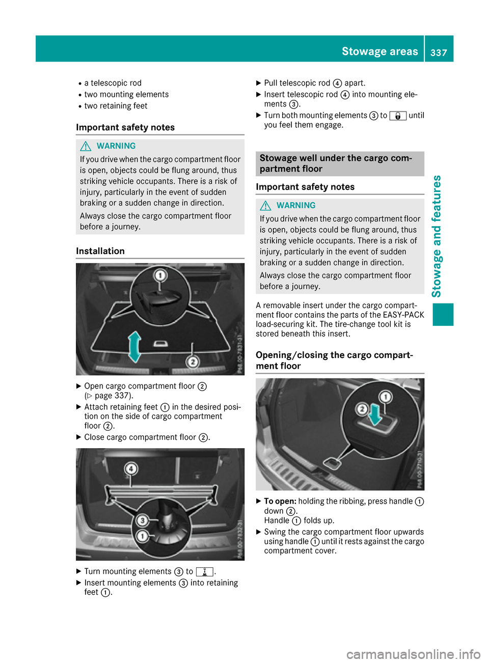
XOpen cargo compartment floor ;
(Ypage 337).
XAttach retaining feet :in the desired posi-
tion on the side of cargo compartment
floor ;.
XClose cargo compartment floor ;.
XTurn mounting elements=to=.
XInsert mounting elements =into retaining
feet :.
XPull telescopic rod ?apart.
XInsert telescopic rod ?into mounting ele-
ments =.
XTurn both mounting elements =to& until
you feel them engage.
Stowage well under the cargo com-
partment floor
Important safety notes
GWARNING
If you drive when the cargo compartment floor is open, objects could be flung around, thus
striking vehicle occupants. There is a risk of
injury, particularly in the event of sudden
braking or a sudden change in direction.
Always close the cargo compartment floor
before a journey.
A removable insert under the cargo compart-
ment floor contains the parts of the EASY-PACK
load-securing kit. The tire-change tool kit is
stored beneath this insert.
Opening/closing the cargo compart-
ment floor
XTo open: holding the ribbing, press handle :
down ;.
Handle :folds up.
XSwing the cargo compartment floor upwards
using handle :until it rests against the cargo
compartment cover.
Stowage areas337
Stowage and features
Z
Page 340 of 450
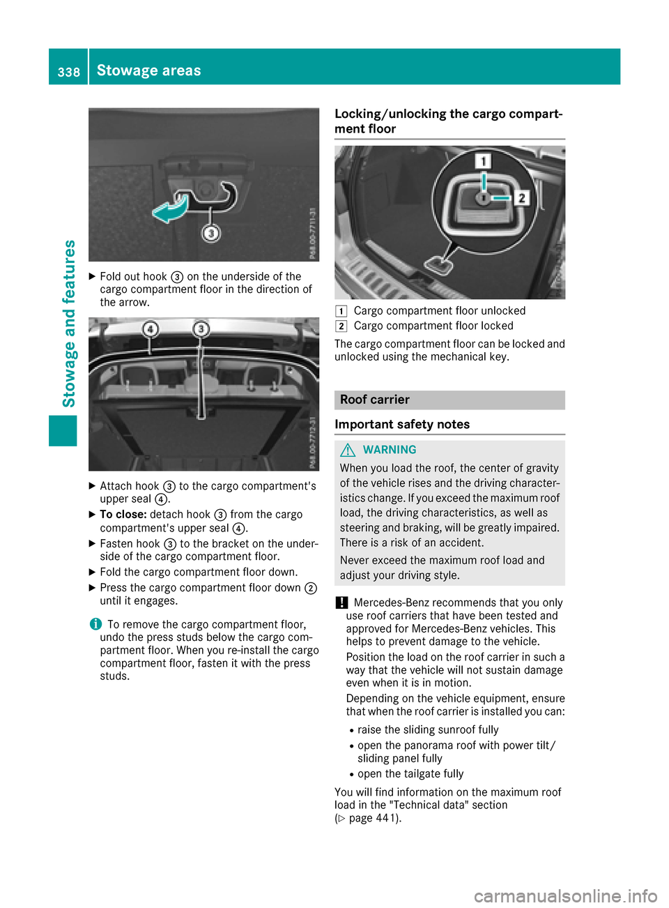
XFold out hook=on the underside of the
cargo compartment floor in the direction of
the arrow.
XAttach hook =to the cargo compartment's
upper seal ?.
XTo close:detach hook =from the cargo
compartment's upper seal ?.
XFasten hook=to the bracket on the under-
side of the cargo compartment floor.
XFold the cargo compartment floor down.
XPress the cargo compartment floor down ;
until it engages.
iTo remove the cargo compartment floor,
undo the press studs below the cargo com-
partment floor. When you re-install the cargo
compartment floor, fasten it with the press
studs.
Locking/unlocking the cargo compart-
ment floor
1Cargo compartment floor unlocked
2Cargo compartment floor locked
The cargo compartment floor can be locked and
unlocked using the mechanical key.
Roof carrier
Important safety notes
GWARNING
When you load the roof, the center of gravity
of the vehicle rises and the driving character-
istics change. If you exceed the maximum roof
load, the driving characteristics, as well as
steering and braking, will be greatly impaired.
There is a risk of an accident.
Never exceed the maximum roof load and
adjust your driving style.
!Mercedes-Benz recommends that you only
use roof carriers that have been tested and
approved for Mercedes-Benz vehicles. This
helps to prevent damage to the vehicle.
Position the load on the roof carrier in such a
way that the vehicle will not sustain damage
even when it is in motion.
Depending on the vehicle equipment, ensure
that when the roof carrier is installed you can:
Rraise the sliding sunroof fully
Ropen the panorama roof with power tilt/
sliding panel fully
Ropen the tailgate fully
You will find information on the maximum roof
load in the "Technical data" section
(
Ypage 441).
338Stowage areas
Stowage and features
Page 341 of 450
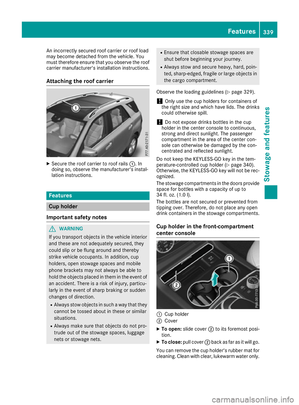
An incorrectly secured roof carrier or roof load
may become detached from the vehicle. You
must therefore ensure that you observe the roof
carrier manufacturer's installation instructions.
Attaching the roof carrier
XSecure the roof carrier to roof rails:. In
doing so, observe the manufacturer's instal-
lation instructions.
Features
Cup holder
Important safety notes
GWARNING
If you transport objects in the vehicle interior
and these are not adequately secured, they
could slip or be flung around and thereby
strike vehicle occupants. In addition, cup
holders, open stowage spaces and mobile
phone brackets may not always be able to
hold the objects placed in them in the event of
an accident. There is a risk of injury, particu-
larly in the event of sharp braking or sudden
changes of direction.
RAlways stow objects in such a way that they cannot be tossed about in these or similar
situations.
RAlways make sure that objects do not pro-
trude out of the stowage spaces, luggage
nets or stowage nets.
REnsure that closable stowage spaces are
shut before beginning your journey.
RAlways stow and secure heavy, hard, poin-
ted, sharp-edged, fragile or large objects in
the cargo compartment.
Observe the loading guidelines (
Ypage 329).
!Only use the cup holders for containers of
the right size and which have lids. The drinks
could otherwise spill.
!Do not expose drinks bottles in the cup
holder in the center console to continuous,
strong and direct sunlight. The passenger
compartment in the area of the center con-
sole can otherwise be damaged by the con-
centrated and reflected sunlight.
Do not keep the KEYLESS-GO key in the tem-
perature-controlled cup holder (
Ypage 340).
Otherwise, the KEYLESS-GO key will not be rec-
ognized.
The stowage compartments in the doors provide space for bottles with a capacity of up to
34 fl. oz. (1.0 l).
The bottles are not secured or prevented from
tipping over. Therefore, do not place any open
drink containers in the stowage compartments.
Cup holder in the front-compartment
center console
:Cup holder
;Cover
XTo open: slide cover ;to its foremost posi-
tion.
XTo close: pull cover ;back as far as it will go.
You can remove the cup holder's rubber mat for
cleaning. Clean with clear, lukewarm water only.
Features339
Stowag ean d features
Z
Page 345 of 450
12 V sockets
General notes
XTurn the SmartKey to position 1in the ignition
lock (Ypage 145).
With the exception of the socket in the front
center console, all sockets can be used for
accessories with a maximum current draw of
240 W (20 A). The socket in the front center
console can be used for accessories with a max- imum current draw of 180 W(15 A). Accessories
include such items as chargers for mobile
phones.
If you use the sockets for long periods when the
engine is switched off, the battery may dis-
charge.
iAn emergency cut-out ensures that the on-
board voltage does not drop too low. If the on- board voltage is too low, the power to the
sockets is automatically cut. This ensures
that there is sufficient power to start the
engine.
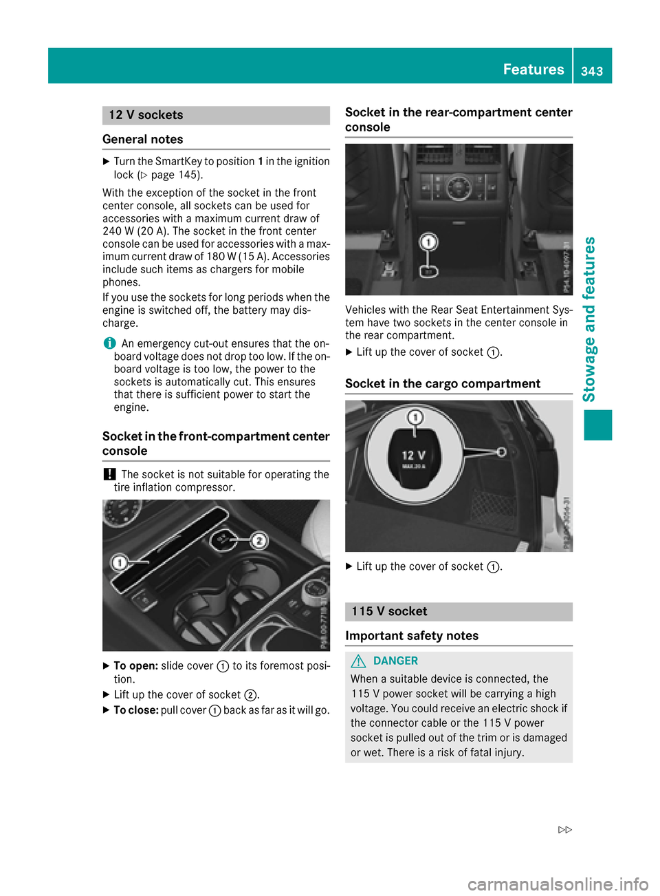
Socket in the front-compartment center
console
!The socket is not suitable for operating the
tire inflation compressor.
XTo open: slide cover :to its foremost posi-
tion.
XLift up the cover of socket ;.
XTo close:pull cover :back as far as it will go.
Socket in the rear-compartment center
console
Vehicles with the Rear Seat Entertainment Sys-
tem have two sockets in the center console in
the rear compartment.
XLift up the cover of socket :.
Socket in the cargo compartment
XLift up the cover of socket:.
115 V socket
Important safety notes
GDANGER
When a suitable device is connected, the
115 V power socket will be carrying a high
voltage. You could receive an electric shock if the connector cable or the 115 V power
socket is pulled out of the trim or is damaged
or wet. There is a risk of fatal injury.
Features343
Stowage and features
Z
Page 348 of 450

The system offers various services, e.g.:
RAutomatic and manual emergency call
RRoadside Assistance call
RMB Info call
You can find information and a description of all
available features under "Owners Online" at
http://www.mbusa.com.
System self-test
After you have switched on the ignition, the sys- tem carries out a self-diagnosis.
A malfunction in the system has been detected
if one of the following occurs:
RThe indicator lamp in the SOS button does not
come on during the system self-test.
RThe indicator lamp in the FRoadside
Assistance button does not light up during
self-diagnosis of the system.
RThe indicator lamp in the ïMB Info call
button does not light up during self-diagnosis
of the system.
RThe indicator lamp in one or more of the fol-
lowing buttons continues to light up red after
the system self-diagnosis:
-SOS button
-F Roadside Assistance call button
-ïMB Info call button
RTheInoperativeor the Service NotActivatedmessage appears in the multi-
function display after the system self-diagno-
sis.
If a malfunction is indicated as outlined above,
the system may not operate as expected. In the event of an emergency, help will have to be
summoned by other means.
Have the system checked at the nearest author-
ized Mercedes-Benz Center or contact the fol-
lowing service hotlines:
Mercedes-Benz Customer Assistance Center at 1-800-FOR-MERCedes (1-800-367-6372) or
1-866-990-9007
Emergency call
Important safety notes
GWARNING
It can be dangerous to remain in the vehicle,
even if you have pressed the SOS button in an emergency if:
Ryou see smoke inside or outside of the vehi-
cle, e.g. if there is a fire after an accident
Rthe vehicle is on a dangerous section of
road
Rthe vehicle is not visible or cannot easily beseen by other road users, particularly when
dark or in poor visibility conditions
There is a risk of an accident and injury.
Leave the vehicle immediately in this or simi-
lar situations as soon as it is safe to do so.
Move to a safe location along with other vehi-
cle occupants. In such situations, secure the
vehicle in accordance with national regula-
tions, e. g. with a warning triangle.
General notes
Observe the notes on system activation
(Ypage 345).
An emergency call is dialed automatically if an
air bag or Emergency Tensioning Device is trig-
gered. You cannot end an automatically trig-
gered emergency call yourself.
An emergency call can also be initiated man-
ually.
As soon as the emergency call has been initi-
ated, the indicator lamp in the SOS button
flashes. The Connecting Call
message
appears in the multifunction display.
The audio output is muted.
Once the connection has been made, the Call
Connectedmessage appears in the multifunc-
tion display.
All important information on the emergency is
transmitted, for example:
Rcurrent location of the vehicle (as determined by the GPS system)
Rvehicle identification number
Rinformation on the severity of the accident
Shortly after the emergency call has been initi-
ated, a voice connection is automatically estab-
346Features
Stowage and features
Page 354 of 450
include text message, e-mail or an automated
call.
The data you receive contains the following
information:
Rthe location where the speed limit was excee-
ded
Rthe time at which the speed limit was excee-
ded
Rthe selected speed limit which was exceeded
Geo fencing
Geo fencing allows you to select areas which the
vehicle should not enter or leave. You will be
informed if the vehicle crosses the boundaries
of the selected areas. You can select the way in
which you receive this information beforehand.
Possible options include text message, e-mail or an automated call.
The area can be determined as either a circle or
a polygon with a maximum of ten corners. You
can specify up to ten areas simultaneously. Dif-
ferent settings are possible for each area.
These settings can be called up under "Owners
Online" at http://www.mbusa.com.
Alternatively, you can trigger an MB Info call and
inform the customer service representative that you wish to activate geo fencing.
Currently inactive areas can be activated by text
message.
Triggering the vehicle alarm
With this function, you can trigger the vehicle's
panic alarm via text message. An alarm sounds
and the exterior lighting flashes. Depending on
the setting, the panic alarm lasts five or ten sec-
onds. Afterwards, the alarm switches off.
Garage door opener
General notes
The HomeLink®garage door opener integrated
in the rear-view mirror allows you to operate up
to three different door and gate systems.
Use the integrated garage door opener only on
garage doors that:
Rhave safety stop and reverse features and
Rmeet current U.S. federal safety standards Once programed, the integrated garage door
opener in the rear-view mirror will assume the
function of the garage door system's remote
control. Please also read the operating instruc-
tions for the garage door system.
When programming a garage door opener, park
the vehicle outside the garage. Do not run the
engine while programming.
Certain garage door drives are incompatible
with the integrated garage door opener. If you
have difficulty programing the integrated garage
door opener, contact an authorized Mercedes-
Benz Center.
Alternatively, you can call the following tele-
phone assistance services:
RUSA: Mercedes-Benz Customer Assistance
Center at 1-800-FOR-MERCedes
RCanada: Customer Service at
1-800-387-0100
RHomeLink®hotline 1-800-355-3515 (free of
charge)
More information on HomeLink
®and/or com-
patible products is also available online at
http://www.homelink.com.
Notes on the declaration of conformity
(
Ypage 29).
USA: FCC ID: CB2HMIHL4
Canada: IC: 279B-HMIHL4
Important safety notes
GWARNING
When you operate or program the garage door
with the integrated garage door opener, per-
sons in the range of movement of the garage
door can become trapped or struck by the
garage door. There is a risk of injury.
When using the integrated garage door
opener, always make sure that nobody is
within the range of movement of the garage
door.
GWARNING
Combustion engines emit poisonous exhaust
gases such as carbon monoxide. Inhaling
these exhaust gases leads to poisoning. There
is a risk of fatal injury. Therefore never leave
the engine running in enclosed spaces with-
out sufficient ventilation.
352Features
Stowage and features