2016 MERCEDES-BENZ GLE-Class Important safety notes
[x] Cancel search: Important safety notesPage 238 of 450

the distance to the vehicle in front, for vehicle
speed, for braking in good time and for staying in
your lane.
!Never tow the vehicle with one axle raised.
This may damage the transfer case. Damage
of this sort is not covered by the Mercedes-
Benz Limited Warranty. All wheels must
remain either on the ground or be fully raised.
Observe the instructions for towing the vehi-
cle with all wheels in full contact with the
ground.
!A function or performance test should only
be carried out on a two-axle dynamometer.
Before you operate the vehicle on such a
dynamometer, please consult a qualified
workshop. You could otherwise damage the
drive train or the brake system.
iIn wintry driving conditions, the maximum
effect of 4MATIC can only be achieved if you
use winter tires (M+S tires), with snow chains
if necessary.
Further information about "Driving off-road"
(
Ypage 186).
DSR (Downhill Speed Regulation)
General notes
DSR is an aid to assist you when driving down-
hill. It keeps the speed of travel at the speed
selected on the on-board computer. The steeper
the downhill gradient, the greater the DSR brak-
ing effect on the vehicle. When driving on flat
stretches of road or on an uphill gradient, the
DSR braking effect is minimal or nonexistent.
DSR controls the vehicle’s speed when it is acti- vated and the transmission is in position D,R or
N. You can drive at a higher or a lower speed
than that set on the on-board computer at any
time by accelerating or braking.
Important safety notes
GWARNING
If the speed driven and the set speed deviate and you activate DSR on a slippery road sur-
face, the wheels may lose traction. There is an
increased danger of skidding and accidents.
Before switching DSR on, please take into
consideration the road surface and the differ- ence between driving speed and the set
speed. If you fail to adapt your driving style, DSR can
neither reduce the risk of accident nor override
the laws of physics. DSR cannot take account of
road, weather and traffic conditions. DSR is only
an aid. You are responsible for the distance to
the vehicle in front, for vehicle speed, for brak-
ing in good time and for staying in your lane.
You are always responsible for keeping control
of the vehicle and for assessing whether the
downhill gradient can be managed. DSR may not always be able to keep to the set speed, depend-
ing on road surface and tire conditions. Select a
set speed suitable for the prevailing conditions
and when necessary, apply the brakes manually.
Activating DSR
XPress button :.
Indicator lamp ;lights up.
The à DSR symbol appears in the multi-
function display.
You can only activate DSR when driving at
speeds below 25 mph (40 km/h).
If the current vehicle speed is too high, the Ã
DSR symbol appears in the multifunction display
with the Max. speed 25 mph
message (Can-
ada: 40 km/h).
If you have activated DSR and you change the
drive program, DSR is deactivated. If you switch
between the offroad and offroad plus drive pro-
grams, DSR remains activated.
Deactivating DSR
XPress button :.
Indicator lamp ;goes out.
The à DSR symbol appears in the multi-
function display with the Off
message.
On vehicles with the Offroad Engineering pack-
age, if you select a different drive program, DSR is also deactivated. If you switch between the
Offroad programs, DSR remains activated.
236Driving system s
Driving an d parking
Page 241 of 450

You can select the Offroad Plus drive program at
speeds below 25 mph (40 km/h).
The Offroad Plus drive program automatically
switches to the Offroad drive program if you
drive faster than 30 mph (45 km/h). TheDrive
more slowlymessage appears in the multi-
function display.
Further information about "Driving off-road"
(
Ypage 186).
LOW RANGE offroad gear (vehicles with
the Offroad Engineering package)
Important safety notes
GWARNING
If you select the LOW RANGE off-road gear on
a slippery road surface, the wheels could lose traction:
Rif you remove your foot from the accelera-
tor pedal when driving
Rif off road ABS intervenes when braking
If the wheels lose traction. the vehicle can no
longer be steered. There is an increased dan-
ger of skidding and accidents.
Never select the LOW RANGE off-road gear
when driving on slippery road surfaces.
GWARNING
If you do not wait for the transfer case gear
change process to complete, the transfer
case could remain in the neutral position. The power transmission to the driven wheels is
then interrupted. There is a danger of the
vehicle rolling away unintentionally. There is a
risk of an accident.
Wait until the transfer case shift process is
completed.
Do not turn off the engine while changing gear
and do not shift the automatic transmission to
another position.
General notes
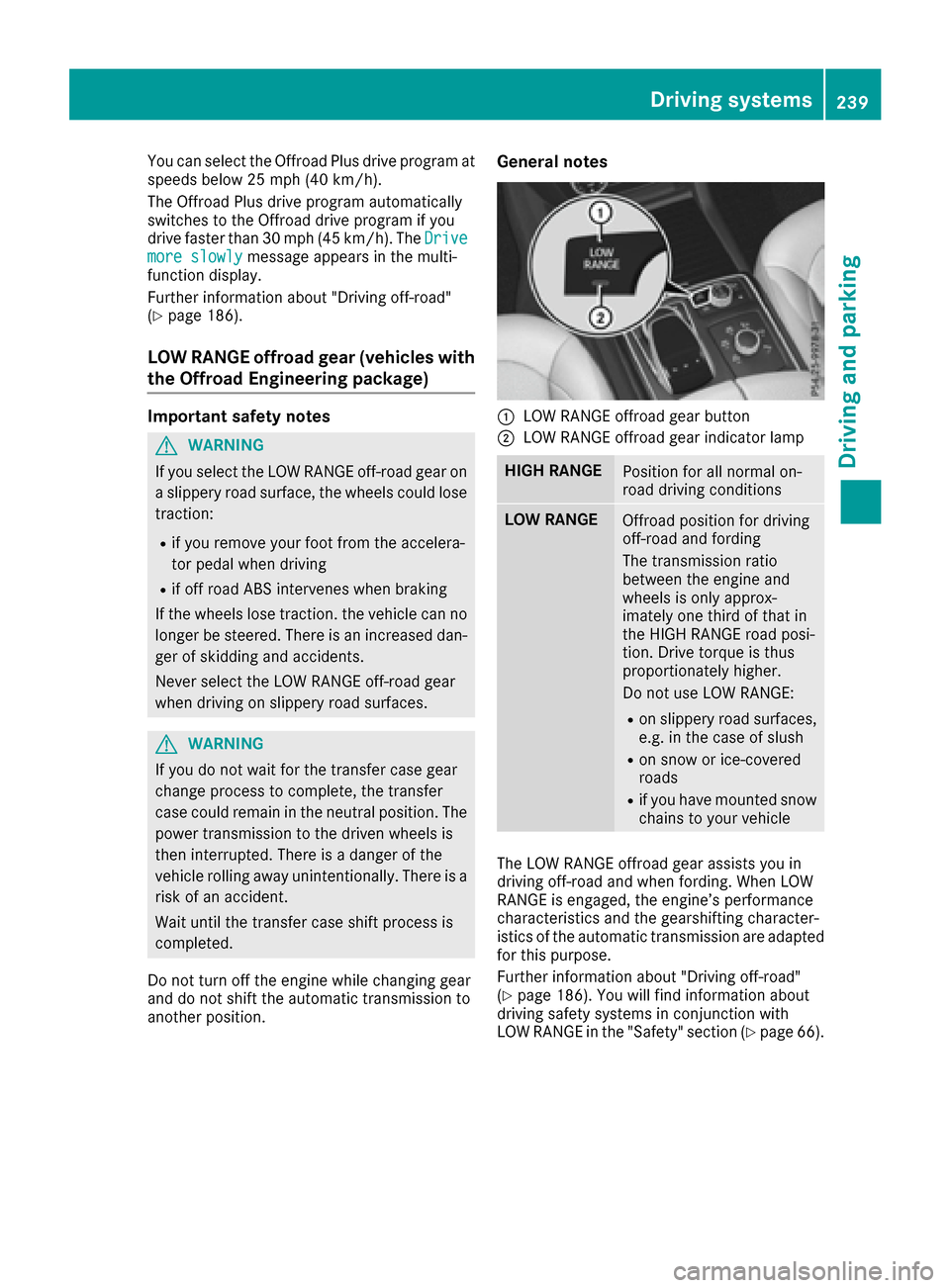
:LOW RANGE offroad gear button
;LOW RANGE offroad gear indicator lamp
HIGH RANGEPosition for all normal on-
road driving conditions
LOW RANGEOffroad position for driving
off-road and fording
The transmission ratio
between the engine and
wheels is only approx-
imately one third of that in
the HIGH RANGE road posi-
tion. Drive torque is thus
proportionately higher.
Do not use LOW RANGE:
Ron slippery road surfaces,
e.g. in the case of slush
Ron snow or ice-covered
roads
Rif you have mounted snow
chains to your vehicle
The LOW RANGE offroad gear assists you in
driving off-road and when fording. When LOW
RANGE is engaged, the engine’s performance
characteristics and the gearshifting character-
istics of the automatic transmission are adapted
for this purpose.
Further information about "Driving off-road"
(
Ypage 186). You will find information about
driving safety systems in conjunction with
LOW RANGE in the "Safety" section (
Ypage 66).
Driving systems239
Driving and parking
Z
Page 244 of 450

ELevel control
FCompass with angle scale
Activating the driving dynamics display
XSwitch on COMAND. You can find further
information in the separate COMAND operat-
ing instructions.
XPress button:.
The driving dynamics display appears in the
COMAND display.
PLUG-IN HYBRID operation
Points to remember
General notes
Hybrid technology combines a fuel efficient
internal combustion engine with a powerful
electric motor. In HYBRIDmode, the hybrid
drive system automatically selects the most effi-
cient operating mode for every driving situation. Drive the vehicle in the usual manner.
To save fuel in HYBRIDmode, the hybrid drive
system switches off the combustion engine as
often as possible during the journey when power
output requirements are low. When power out-
put requirements are low, the electric motor
powers the vehicle. The engine is switched on,
even while the vehicle is in motion, when a
higher power output is required. The engine is
usually switched off when the vehicle is station-
ary. Consequently, there is usually no engine
idling as with combustion engine vehicles.
For pulling away and accelerating, the electric
motor supports the internal combustion engine
using the power stored in the high-voltage bat-
tery. In addition, the power is used for electric
driving, operation of the electric refrigerant
compressor and to supply the 12 V on-board electrical system. In this way the hybrid drive
system helps to reduce your vehicle's fuel con-
sumption.
Observe the driving tips on plug-in hybrid oper-
ation (
Ypage 252).
Recuperative Brake System
If you release the accelerator pedal when the
vehicle is in motion, overrun recuperation is ini-
tiated. The electric motor is operated as a gen-
erator when in overrun mode and when you
brake. Hybrid technology converts the kinetic
energy of the vehicle into electricity and stores
it in the high-voltage battery.
Observe the important safety notes for the
Recuperative Brake System (
Ypage 44).
Important safety notes
If the engine is switched off by the ECO start/
stop function, you open the driver's door and
unfasten your seat belt:
Ra message appears in the multifunction dis-
play and
Ra warning tone sounds
Further information (
Ypage 299).
All of the vehicle's systems remain active, if:
Rthe vehicle is stationary
Rthe combustion engine is switched off and
Rthe READY indicator in the instrument cluster
lights up
If you remove your foot from the brake pedal
while in transmission position D or R, the vehicle
may pull away automatically.
Observe the notes on the READY display of the
ECO start/stop function (
Ypage 253).
Vehicles with an electric motor generate much
less driving noise than vehicles with internal
combustion engines. As a result, your vehicle
may not be heard by other road users in certain
situations. This is the case, for example, when
you are parking and your vehicle is not seen by
other road users.
This requires you to adopt a particularly antici-
patory driving style, as it is necessary to allow
for the possibility that other road users may
behave erratically.
Depending on the vehicle's equipment and
country-specific regulations, the vehicle can be
equipped with Acoustic Vehicle Indication.
242PLUG-IN HYBRID operation
Driving and parking
Page 258 of 450

Hybrid drive system
ProblemPossible causes/consequences andMSolutions
The hybrid drive system
has been switched off
automatically.You have been in an accident.
The hybrid drive system remains switched off if:
Rthe internal combustion engine cannot be restarted after a few
seconds.
Rthe red6restraint system warning lamp in the instrument clus-
ter is lit.
XConsult a qualified specialist workshop.
The hybrid drive system
has been switched off
automatically. The multi-
function display also
shows a display mes-
sage.An electrical short circuit has occurred in the hybrid drive system or an
electrical connection has been disconnected.
XObserve the additional display messages in the multifunction dis-
play (Ypage 280).
XConsult a qualified specialist workshop.
Towing a trailer
Important safety notes
GWARNING
Installing an unsuitable ball coupling may
result in overloading of the trailer tow hitch
and the rear axle. This applies especially if the ball coupling in question is longer or angled
differently. This could seriously impair the
driving characteristics and the trailer can
come loose. There is a risk of an accident.
You should only ever install a ball coupling
that has the permissible dimensions and that
is designed to meet your trailer-towing
requirements. Do not modify the ball coupling
or the trailer tow hitch.
You will find the values approved by the manu-
facturer on the vehicle identification plates and
those for the towing vehicle under "Technical
data" (
Ypage 445).
GWARNING
If the ball coupling is not installed correctly or not secured with the bolt provided and the
corresponding spring cotter, the trailer may
come loose. There is a risk of an accident.
Always install and secure the ball coupling as
described. Before every journey, ensure that
the ball coupling is secured with the bolt and
the corresponding spring cotter.
GWARNING
When the vehicle/trailer combination begins
to lurch, you could lose control of it. The vehi- cle/trailer combination could even rollover.
There is a risk of an accident.
On no account should you attempt to
straighten up the vehicle/trailer combination
by increasing the speed. Reduce vehicle
speed and do not countersteer. Apply the
brake as necessary.
Please observe the manufacturer's operating
instructions for the trailer coupling if a detach-
able trailer coupling is used.
Couple and uncouple the trailer carefully. If you
do not couple the trailer to the towing vehicle
correctly, the trailer could become detached.
Make sure that the following values are not
exceeded:
Rthe permissible trailer drawbar noseweight
Rthe permissible trailer load
Rthe permissible rear axle load of the towing
vehicle
Rthe maximum permissible gross vehicle
weight of both the towing vehicle and the
trailer
256Towing a trailer
Driving and parking
Page 265 of 450

Useful information
i
This Operator's Manual describes all models
and all standard and optional equipment of
your vehicle available at the time of publica-
tion of the Operator's Manual. Country-spe-
cific differences are possible. Please note
that your vehicle may not be equipped with all
features described. This also applies to
safety-related systems and functions.
iRead the information on qualified specialist
workshops (Ypage 29).
Important safety notes
GWARNING
If you operate information systems and com-
munication equipment integrated in the vehi-
cle while driving, you will be distracted from
traffic conditions. You could also lose control
of the vehicle. There is a risk of an accident.
Only operate the equipment when the traffic
situation permits. If you are not sure that this
is possible, park the vehicle paying attention
to traffic conditions and operate the equip-
ment when the vehicle is stationary.
You must observe the legal requirements for the
country in which you are currently driving when
operating the on-board computer.
PLUG-IN HYBRID vehicles only:
GWARNING
If the instrument cluster has failed or mal-
functioned, you may not recognize function
restrictions in systems relevant to safety. The
operating safety of your vehicle may be
impaired. There is a risk of an accident.
Pull over as soon as it is safe to do so and
consult a qualified specialist workshop.
All vehicles, except PLUG-IN HYBRID vehi-
cles:
The on-board computer only shows messages or
warnings from certain systems in the multifunc-
tion display. You should therefore make sure
your vehicle is operating safely at all times. For an overview, see the instrument panel illus-
tration (
Ypage 34).
Displays and operation
Instrument cluster lighting
The lighting in the instrument cluster, in the dis-
plays and the controls in the vehicle interior can
be adjusted using the brightness control knob.
The brightness control knob is located on the
bottom left of the instrument cluster
(
Ypage 34).
XTurn the brightness control knob clockwise or
counter-clockwise.
If you turn the light switch to
Ã,Tor
L, the brightness is dependent upon the
brightness of the ambient light.
iThe light sensor in the instrument cluster
automatically controls the brightness of the
multifunction display.
In daylight, the displays in the instrument
cluster are not illuminated.
Speedometer with segments
The speedometer is divided into segments only
on vehicles with DISTRONIC PLUS.
The segments in the speedometer indicate
which speed range is available.
RDISTRONIC PLUS activated (Ypage 193):
One or two segments in the set speed range
light up.
RDISTRONIC PLUS detects a vehicle in front
that is driving at a slower speed than the
stored speed:
The segments between the speed of the vehi- cle in front and the stored speed light up.
Tachometer
!
Do not drive in the overrevving range, as this
could damage the engine.
The red band in the tachometer indicates the
engine's overrevving range.
The fuel supply is interrupted to protect the
engine when the red band is reached.
Displays and operation263
On-board computer and displays
Z
Page 324 of 450

Warning/
indicator
lampNSignal type
Possible causes/consequences and M
Solutions
÷NThe yellow ESP®warning lamp flashes while the vehicle is in motion.
ESP®or traction control has intervened because there is a risk of skidding or at
least one wheel has started to spin.
Cruise control or DISTRONIC PLUS is deactivated.
XWhen pulling away, only depress the accelerator pedal as far as necessary.
XEase off the accelerator pedal while the vehicle is in motion.
XAdapt your driving style to suit the road and weather conditions.
XDo not deactivate ESP®.
In rare cases (
Ypage 72), it may be best to deactivate ESP®.
Observe the important safety notes on ESP®(Ypage 72).
åN The yellow ESP®OFF warning lamp is lit while the engine is running.
PLUG-IN HYBRID vehicles:
The yellow ESP
®OFF warning lamp is lit in the READY driving status.
ESP®is deactivated.
GWARNING
If ESP
®is switched off, ESP®is unable to stabilize the vehicle.
Further driving systems or driving safety systems are thus restricted, e.g. Active
Blind Spot Assist. The system does not perform course-correcting brake applica-
tions.
There is an increased risk of skidding and an accident.
XReactivate ESP®.
In rare cases (
Ypage 72), it may be best to deactivate ESP®.
Observe the important safety notes on ESP®(Ypage 72).
XAdapt your driving style to suit the road and weather conditions.
If ESP
®cannot be activated:
XDrive on carefully.
XContact a qualified specialist workshop and have ESP®checked.
322Warning and indicator lamps in the instrument cluster
On-board computer and displays
Page 332 of 450

Stowage spaces
Important safety notes
GWARNING
If objects in the passenger compartment are
stowed incorrectly, they can slide or be
thrown around and hit vehicle occupants.
There is a risk of injury, particularly in the
event of sudden braking or a sudden change
in direction.
RAlways stow objects so that they cannot be
thrown around in such situations.
RAlways make sure that objects do not pro-
trude from stowage spaces, parcel nets or
stowage nets.
RClose the lockable stowage spaces while
driving.
RStow and secure objects that are heavy,
hard, pointy, sharp-edged, fragile or too
large in the cargo compartment.
Observe the loading guidelines (
Ypage 329).
Glove box
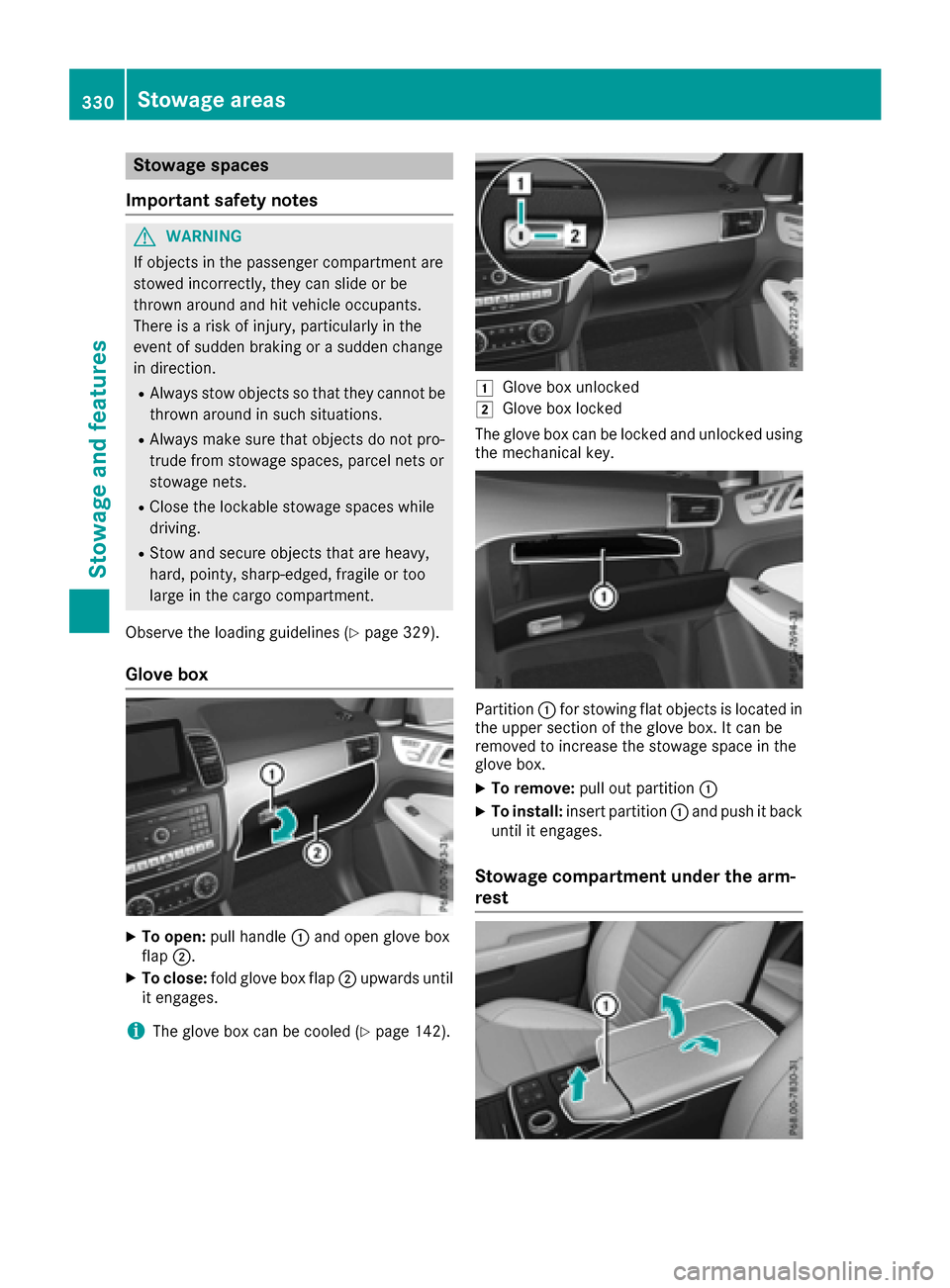
XTo open: pull handle :and open glove box
flap ;.
XTo close: fold glove box flap ;upwards until
it engages.
iThe glove box can be cooled (Ypage 142).
1Glove box unlocked
2Glove box locked
The glove box can be locked and unlocked using the mechanical key.
Partition :for stowing flat objects is located in
the upper section of the glove box. It can be
removed to increase the stowage space in the
glove box.
XTo remove: pull out partition :
XTo install:insert partition :and push it back
until it engages.
Stowage compartment under the arm-
rest
330Stowage areas
Stowage and features
Page 334 of 450

gory. The front-passenger front air bag could
deploy without cause, or may fail to deploy inthe event of an accident. This poses an
increased risk of injury or even fatal injury.
Always observe the permissible gross weight
of 4.4 lb (2 kg). Stow and secure heavy
objects in the cargo compartment.
Stowage nets are located in the front-passenger
footwell and on the back of the driver's and the
front-passenger seat.
Observe the loading guidelines (
Ypage 329)
and the safety notes regarding stowage spaces
(
Ypage 330).
Through-loading facility in the rear
If objects or loads are not secured when being
transported in the through-loading facility, they
could slip or be thrown around and thereby hit
vehicle occupants.
Observe the loading guidelines (
Ypage 329)
and the safety notes regarding stowage spaces
(
Ypage 330).
The through-loading facility is opened from the
cargo compartment.
XFold down the rear seat armrest.
XPull the center head restraint on the rear
bench seat into the uppermost position
(
Ypage 102).
XSlide release catch :to the left and swing
flap ;to the left until it is lying on the rear
side of the rear bench seat.
XPush cover =forward until it is lying on the
rear seat armrest.
Cargo compartment enlargement
Important safety notes
GWARNING
If the rear bench seat/rear seat and seat
backrest are not engaged they could fold for-
wards, e.g. when braking suddenly or in the
event of an accident.
RThe vehicle occupant would thereby be
pushed into the seat belt by the rear bench
seat/rear seat or by the seat backrest. The
seat belt can no longer offer the intended
level of protection and could even cause
injuries.
RObjects or loads in the trunk/cargo com-
partment cannot be restrained by the seat
backrest.
There is an increased risk of injury.
Before every trip, make sure that the seat
backrests and the rear bench seat/rear seat
are engaged.
Make sure that the seat backrest and the seat
cushion are correctly engaged in position. To do
so, pull firmly on the seat backrest.
!Fold the seat cushion upwards before fold-
ing the rear bench seat forward. Otherwise,
the backrests may be damaged.
When the backrest is folded forwards, the
front seats should not be moved to their rear-
most position. Otherwise, the front seats and
the rear bench seat could be damaged.
332Stowage areas
Stowage and features