2016 MERCEDES-BENZ GLE-Class ignition
[x] Cancel search: ignitionPage 317 of 450

Display messagesPossible causes/consequences andMSolutions
Â
Key Not Detected(reddisplay message )
The SmartKey is no tin th evehicle.
A warning tone also sounds.
If th eengin eis switched off ,you can no longer loc kth evehicl ecen-
trally or start th eengine.
XPull ove rand stop th evehicl esafely as soo nas possible, payin g
attention to roa dand traffic conditions.
XSecur eth evehicl eagainst rollin gaway (Ypage 178).
XLocate th eSmartKey.
Becaus ethere is interferenc efrom astron gsource of radi owaves, th e
ke yis no tdetecte dwhils tth eengin eis running.
A warning tone also sounds.
XPull ove rand stop th evehicl esafely as soo nas possible, payin g
attention to roa dand traffic conditions.
XSecur eth evehicl eagainst rollin gaway (Ypage 178).
XInsertth eSmartKey int oth eignition loc kand bring int oke ymode.
Â
Remove 'Start 'But ‐ton and Insert Key
RThe SmartKey detection function has atemporar ymalfunction or is
faulty.
RThe SmartKey is continually undetected.
A warning tone also sounds.
XInser tth eSmartKey int oth eignition loc kand tur nit to th edesire d
position .
XVisitaqualified specialist workshop .
Warning and indicat orlamps in the instrume nt cluster
General notes
Some systems carry out aself-diagnosis when th eignition is switched on .Therefore ,som eindicator
and warning lamp smay ligh tup or flas htemporarily. This behavio ris non-critical .These indicator
and warning lamp sonly indicat e amalfunction if they ligh tup or flas hafter starting th eengin eor
whils tdriving.
Warning and indicator lamps in the instrument cluster315
On-board computer and displays
Z
Page 327 of 450

Engine
Warning/
indicator
lampNSignal type
Possible causes/consequences and M
Solutions
;NThe yellow Check Engine warning lamp lights up while the engine is running.
There may be a malfunction, for example:
Rin the engine management
Rin the fuel injection system
Rin the exhaust system
Rin the ignition system (for vehicles with gasoline engines)
Rin the fuel system
The emission limit values may be exceeded and the engine may be in emergency
mode.
XVisit a qualified specialist workshop immediately.
Vehicles with a diesel engine: the fuel tank has been run dry (
Ypage 166).
XStart the engine three to four times after refueling.
If the yellow Check Engine warning lamp goes out, emergency running mode is
canceled. The vehicle need not be checked.
In some states, you must immediately visit a qualified specialist workshop as soon
as the yellow Check Engine warning lamp lights up. This is due to the legal require-
ments in effect in these states. If in doubt, check whether such legal regulations
apply in the state in which you are currently driving.
8N The yellow reserve fuel warning lamp lights up while the engine is running.
The fuel level has dropped into the reserve range.
XRefuel at the nearest gas station.
8N The yellow reserve fuel warning lamp flashes while the vehicle is in motion.
In addition, the ;Check Engine warning lamp may light up.
The fuel filler cap is not closed correctly or the fuel system is leaking.
XCheck that the fuel filler cap is correctly closed.
XIf the fuel filler cap is not correctly closed: close the fuel filler cap.
XIf the fuel filler cap is closed:visit a qualified specialist workshop.
?NThe red coolant warning lamp lights up while the engine is running and the
coolant temperature gauge is at the start of the scale.
The temperature sensor for the coolant temperature gage is defective.
The coolant temperature is no longer being monitored. There is a risk of engine
damage if the coolant temperature is too high.
XPull over and stop the vehicle safely and switch off the engine, paying attention
to road and traffic conditions. Do not continue driving under any circumstances.
XSecure the vehicle against rolling away (Ypage 178).
XConsult a qualified specialist workshop.
Warning and indicator lamps in the instrument cluster325
On-board computer and displays
Z
Page 342 of 450

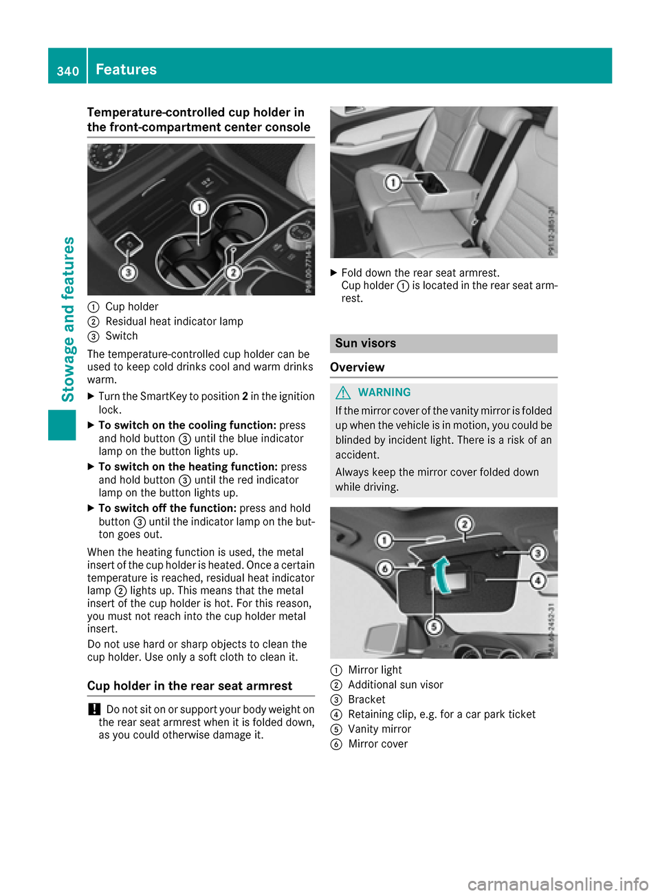
Temperature-controlled cup holder in
the front-compartment center console
:Cup holder
;Residual heat indicator lamp
=Switch
The temperature-controlled cup holder can be
used to keep cold drinks cool and warm drinks
warm.
XTurn the SmartKey to position 2in the ignition
lock.
XTo switch on the cooling function: press
and hold button =until the blue indicator
lamp on the button lights up.
XTo switch on the heating function: press
and hold button =until the red indicator
lamp on the button lights up.
XTo switch off the function: press and hold
button =until the indicator lamp on the but-
ton goes out.
When the heating function is used, the metal
insert of the cup holder is heated. Once a certain
temperature is reached, residual heat indicator
lamp ;lights up. This means that the metal
insert of the cup holder is hot. For this reason,
you must not reach into the cup holder metal
insert.
Do not use hard or sharp objects to clean the
cup holder. Use only a soft cloth to clean it.
Cup holder in the rear seat armrest
!Do not sit on or support your body weight on
the rear seat armrest when it is folded down,
as you could otherwise damage it.
XFold down the rear seat armrest.
Cup holder :is located in the rear seat arm-
rest.
Sun visors
Overview
GWARNING
If the mirror cover of the vanity mirror is folded
up when the vehicle is in motion, you could be
blinded by incident light. There is a risk of an
accident.
Always keep the mirror cover folded down
while driving.
:Mirror light
;Additional sun visor
=Bracket
?Retaining clip, e.g. for a car park ticket
AVanity mirror
BMirror cover
340Features
Stowag ean d features
Page 344 of 450

XTo open:slide cover :to its foremost posi-
tion.
XFold cover =of the insert upwards.
XTo remove the insert: push insert=to the
left ?.
Insert =slides out slightly to the right.
XLift insert =up; and out.
XTo re-install the insert: place insert=into
the holder and press it down on the right until
it engages.
XTo close: pull cover :back as far as it will go.
Rear-compartment ashtray
!Close the ashtray when it is not in use and
before you fold the rear seats forward. You
can otherwise damage the ashtray.
Vehicles without a Rear Seat Entertainment Sys-
tem have an ashtray in the center console in the
rear compartment.
XTo open: briefly press cover ;at the top.
The ashtray opens.
XTo remove the insert: push into recess=
from the right.
Ashtray insert :slides out slightly to the
right.
XLift insert :up and out.
XTo re-install the insert: place insert:into
the holder and press down on the right until it
engages.
Cigarette lighter
GWARNING
You can burn yourself if you touch the hot
heating element or the socket of the cigarette lighter.
In addition, flammable materials can ignite if:
Rthe hot cigarette lighter falls
Ra child holds the hot cigarette lighter to
objects, for example
There is a risk of fire and injury.
Always hold the cigarette lighter by the knob.
Always make sure that the cigarette lighter is
out of reach of children. Never leave children
unsupervised in the vehicle.
!The cigarette lighter in the center console in
the front compartment is not intended for
operating the tire inflation compressor.
Your attention must always be focused on the
traffic conditions. Only use the cigarette lighter
when road and traffic conditions permit.
XTurn the SmartKey to position 2in the ignition
lock (Ypage 145).
XTo open: slide cover :to its foremost posi-
tion.
XPress in cigarette lighter ;.
Cigarette lighter ;will pop out automatically
when the heating element is red-hot.
XTo close: pull cover :back as far as it will go.
342Features
Stowag ean d features
Page 345 of 450

12 V sockets
General notes
XTurn the SmartKey to position 1in the ignition
lock (Ypage 145).
With the exception of the socket in the front
center console, all sockets can be used for
accessories with a maximum current draw of
240 W (20 A). The socket in the front center
console can be used for accessories with a max- imum current draw of 180 W(15 A). Accessories
include such items as chargers for mobile
phones.
If you use the sockets for long periods when the
engine is switched off, the battery may dis-
charge.
iAn emergency cut-out ensures that the on-
board voltage does not drop too low. If the on- board voltage is too low, the power to the
sockets is automatically cut. This ensures
that there is sufficient power to start the
engine.
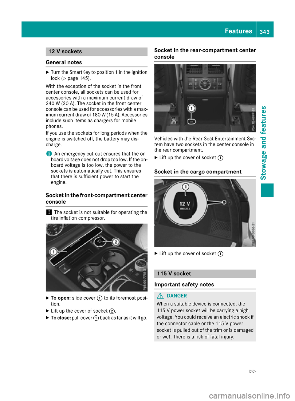
Socket in the front-compartment center
console
!The socket is not suitable for operating the
tire inflation compressor.
XTo open: slide cover :to its foremost posi-
tion.
XLift up the cover of socket ;.
XTo close:pull cover :back as far as it will go.
Socket in the rear-compartment center
console
Vehicles with the Rear Seat Entertainment Sys-
tem have two sockets in the center console in
the rear compartment.
XLift up the cover of socket :.
Socket in the cargo compartment
XLift up the cover of socket:.
115 V socket
Important safety notes
GDANGER
When a suitable device is connected, the
115 V power socket will be carrying a high
voltage. You could receive an electric shock if the connector cable or the 115 V power
socket is pulled out of the trim or is damaged
or wet. There is a risk of fatal injury.
Features343
Stowage and features
Z
Page 346 of 450

RUse only connector cables that are dry and
free of damage.
RWhen the ignition is off, make sure that the
115 V power socket is dry.
RHave the 115 V power socket checked or
replaced immediately at a qualified speci-
alized workshop if it is damaged or has been
pulled out of the trim.
RNever plug the connector cable into a 115 V
power socket that is damaged or has been
pulled out of the trim.
GDANGER
If you reach into the power socket or plug
inappropriate devices into the power socket,
you could receive an electric shock. There is a
risk of fatal injury.
Only connect appropriate devices to the
power socket.
!Note that work and repairs on the 115 V
power socket should only be carried out by
qualified specialist personnel.
General notes
The 115 Vpower socket provides an alternating
voltage of 115 V so that small electronic devices
can be connected. These devices, such as
games consoles, chargers and laptops, must not consume more than a maximum of 150 watts
altogether.
Requirements for operation of these devices:
Rthe electronic device that you connect has a
suitable connector and conforms to stand-
ards specific to the country you are in.
Rthe plug of the electronic device is plugged
correctly into 115 V power socket.
Rthe maximum wattage of the device to be
connected must not exceed 150 watts.
Rthe on-board power supply is within a permis-
sible voltage range.
Rthe 12 V sockets in the rear compartment and
the cargo compartment are operational.
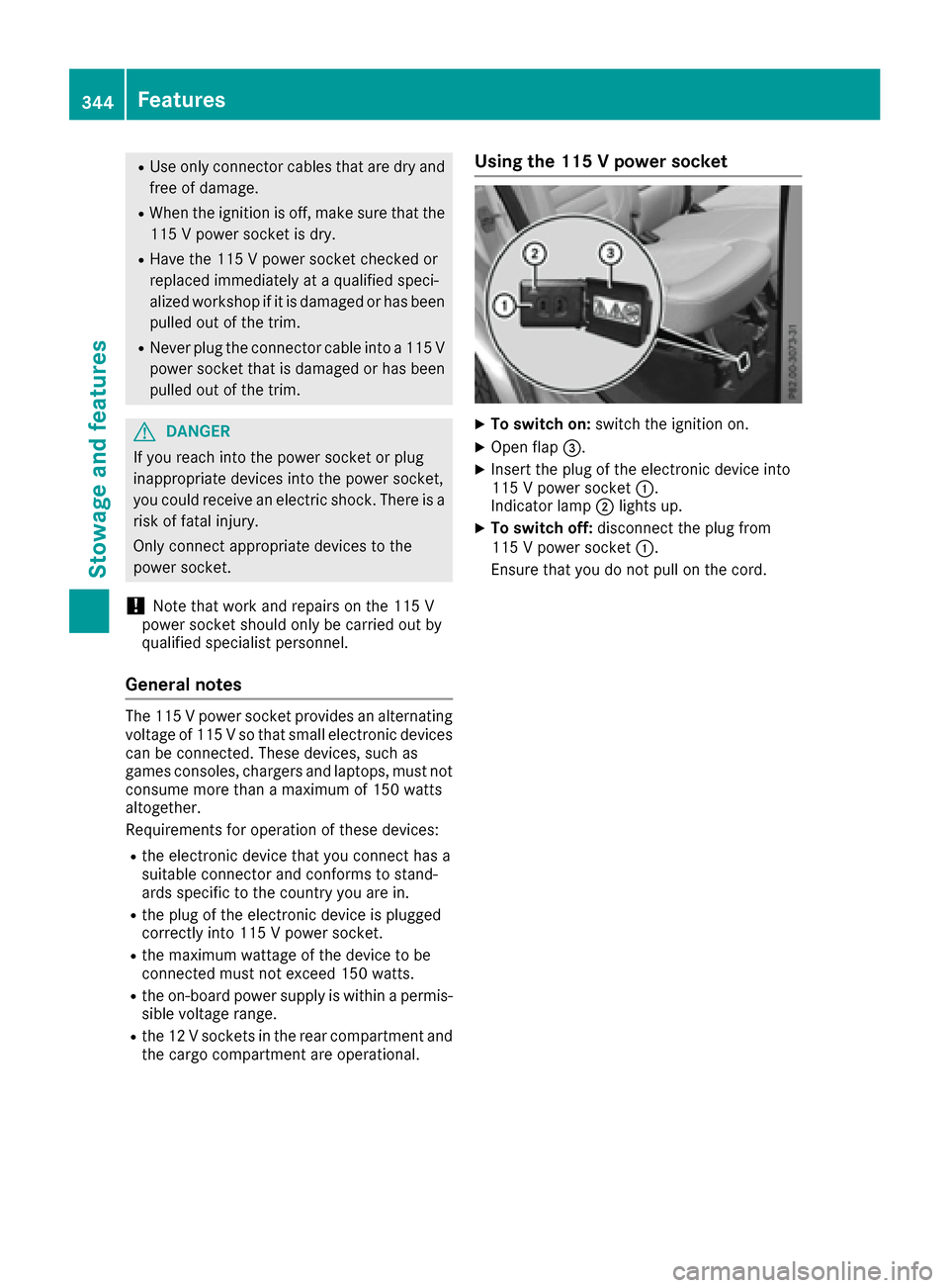
Using the 115 V power socket
XTo switch on: switch the ignition on.
XOpen flap=.
XInsert the plug of the electronic device into
115 V power socket :.
Indicator lamp ;lights up.
XTo switch off: disconnect the plug from
115 V power socket :.
Ensure that you do not pull on the cord.
344Features
Stowage and features
Page 348 of 450

The system offers various services, e.g.:
RAutomatic and manual emergency call
RRoadside Assistance call
RMB Info call
You can find information and a description of all
available features under "Owners Online" at
http://www.mbusa.com.
System self-test
After you have switched on the ignition, the sys- tem carries out a self-diagnosis.
A malfunction in the system has been detected
if one of the following occurs:
RThe indicator lamp in the SOS button does not
come on during the system self-test.
RThe indicator lamp in the FRoadside
Assistance button does not light up during
self-diagnosis of the system.
RThe indicator lamp in the ïMB Info call
button does not light up during self-diagnosis
of the system.
RThe indicator lamp in one or more of the fol-
lowing buttons continues to light up red after
the system self-diagnosis:
-SOS button
-F Roadside Assistance call button
-ïMB Info call button
RTheInoperativeor the Service NotActivatedmessage appears in the multi-
function display after the system self-diagno-
sis.
If a malfunction is indicated as outlined above,
the system may not operate as expected. In the event of an emergency, help will have to be
summoned by other means.
Have the system checked at the nearest author-
ized Mercedes-Benz Center or contact the fol-
lowing service hotlines:
Mercedes-Benz Customer Assistance Center at 1-800-FOR-MERCedes (1-800-367-6372) or
1-866-990-9007
Emergency call
Important safety notes
GWARNING
It can be dangerous to remain in the vehicle,
even if you have pressed the SOS button in an emergency if:
Ryou see smoke inside or outside of the vehi-
cle, e.g. if there is a fire after an accident
Rthe vehicle is on a dangerous section of
road
Rthe vehicle is not visible or cannot easily beseen by other road users, particularly when
dark or in poor visibility conditions
There is a risk of an accident and injury.
Leave the vehicle immediately in this or simi-
lar situations as soon as it is safe to do so.
Move to a safe location along with other vehi-
cle occupants. In such situations, secure the
vehicle in accordance with national regula-
tions, e. g. with a warning triangle.
General notes
Observe the notes on system activation
(Ypage 345).
An emergency call is dialed automatically if an
air bag or Emergency Tensioning Device is trig-
gered. You cannot end an automatically trig-
gered emergency call yourself.
An emergency call can also be initiated man-
ually.
As soon as the emergency call has been initi-
ated, the indicator lamp in the SOS button
flashes. The Connecting Call
message
appears in the multifunction display.
The audio output is muted.
Once the connection has been made, the Call
Connectedmessage appears in the multifunc-
tion display.
All important information on the emergency is
transmitted, for example:
Rcurrent location of the vehicle (as determined by the GPS system)
Rvehicle identification number
Rinformation on the severity of the accident
Shortly after the emergency call has been initi-
ated, a voice connection is automatically estab-
346Features
Stowage and features
Page 351 of 450

The mobile phone is no longer connected to the
multimedia system.
However, if you want to use your mobile phone,
do so only when the vehicle is stationary and in
a safe location.
Downloading destinations in COMAND
Downloading destinations
Downloading destinations gives you access to a
database with over 15 million points of interest
(POIs). These can be downloaded on the navi-
gation system in your vehicle. If you know the
destination, the address can be downloaded.
Alternatively, you can obtain the location of
Points of Interest (POIs)/important destinations
in the vicinity.
Furthermore, you can download routes with up
to four way points.
You are prompted to confirm route guidance to
the address entered.
XSelect Yesby turning 3or sliding 1
the controller and confirm with 7.
The system calculates the route and subse-
quently starts the route guidance with the
address entered.
If you select No
the address can be stored in
the address book.
The destination download function is available
if:
Rthe vehicle is equipped with a navigation sys-
tem.
Rthe relevant mobile phone network is availa-
ble and data transfer is possible.
Route Assistance
This service is part of the mbrace PLUS Package
and cannot be purchased separately.
You can use the route assistance function even
if the vehicle is not equipped with a navigation
system.
Within the framework of this service, you receive
a professional and reliable form of navigation
support without having to leave your vehicle.
The customer service representative finds a
suitable route depending on your vehicle's cur-
rent position and the desired destination. You
will then be guided live through the current route
section.
Search & Send
General notes
To use "Search & Send", your vehicle must be
equipped with mbrace and a navigation system.
Additionally, an mbrace service subscription
must be completed.
"Search & Send" is a destination entry service. A
destination address which is found on Google
Maps
®can be transferred via mbrace directly to
your vehicle's navigation system.
Specifying and sending the destination
address
XGo to the website http://maps.google.com
and enter a destination address into the entry
field.
XTo send the destination address to the e-
mail address of your mbrace account:
click on the corresponding button on the web-
site.
Example:
If you select 'Send to vehicle' and then
'Mercedes-Benz', the destination address will
be sent to your vehicle.
XWhen the "Send" dialog window appears:
Enter the e-mail address you specified when
setting up your mbrace account into the cor-
responding field.
XClick "Send".
Information on specific commands such as
"Address entry" or "Send" can be found on the
website.
Calling up a transmitted destination
address
XTurn the SmartKey to position 2in the ignition
lock (Ypage 145).
The transmitted destination address is loaded
into the vehicle's navigation system.
A display message appears, asking whether
navigation should be started.
XSelect Yesby turning 3or sliding 1
the controller and confirm with 7.
The system calculates the route and subse-
quently starts the route guidance with the
address entered.
If you select No
the address can be stored in
the address book.
Features349
Stowage and features
Z