2016 MERCEDES-BENZ GL tow
[x] Cancel search: towPage 23 of 462
Maximum loaded vehicle weight
(definition) .................................... .4 25
Maximum permissible tire pres-
sure (definition) ............................ .4 26
Maximum tire load ......................... 423
Maximum tire load (definition) ....... 426
MOExtended tires .......................... 406
Optional equipment weight (defi-
nition) ............................................ 426
PSI (pounds per square inch) (def-
inition) .......................................... .4 26
Replacing ....................................... 427
Service life ..................................... 406
Sidewall (definition) ....................... 426
Speed rating (definition) ................ 425
Storing .......................................... .4 27
Structure and characteristics
(definition) ..................................... 424
Temperature .................................. 420
TIN (Tire Identification Number)
(definition) ..................................... 426
Tire bead (definition) ..................... .4 26
Tire pressure (definition) ................ 426
Tire pressures (recommended) ...... 425
Tire size (data) ............................... 432
Tire size designation, load-bearing
capacity, speed rating .................... 421
Tire tread ....................................... 405
Tire tread (definition) ..................... 426
Total load limit (definition) ............. 427
Traction ......................................... 420
Traction (definition) ....................... 426
Tread wear ..................................... 420
TWR (permissible trailer drawbar
noseweight) (definition) ................. 426
Uniform Tire Quality Grading
Standards ...................................... 419
Uniform Tire Quality Grading
Standards (definition) .................... 425
Wear indicator (definition) ............. 427
Wheel and tire combination ........... 434
Wheel rim (definition) .................... 425
see Flat tire
Tool
see Vehicle tool kit
Top Tether ............................................ 64
Tow -s
tarting
Emergency engine starting ............ 400 Important safety notes .................. 397
Towing a trailer
Active Parking Assist ..................... 231
Axle load, permissible .................... 458
Cleaning the trailer tow hitch ......... 381
Coupling up a trailer ...................... 266
Decoupling a trailer ....................... 268
Driving tips .................................... 264
ESP ®
(Electronic Stability Pro-
gram) ............................................... 75
Important safety notes .................. 263
Installing the ball coupling ............. 265
Lights display message .................. 303
Mounting dimensions .................... 457
Power supply ................................. 269
Pulling away with a trailer .............. 168
Removing the ball coupling ............ 269
Trailer drive program ..................... 256
Trailer loads ................................... 458
Towing away
Important safety guidelines ........... 397
Installing the towing eye ................ 398
Removing the towing eye ............... 399
With both axles on the ground ....... 399
Trailer coupling
see Towing a trailer
Trailer loads and drawbar nose-
weights ............................................... 269
Trailer towing
Active Blind Spot Assist ................. 251
Active Lane Keeping Assist ............ 254
Blind Spot Assist ............................ 246
PARKTRONIC ................................. 226
Permissible trailer loads and
drawbar noseweights ..................... 269
Transfer case ..................................... 182
Transmission
see Automatic transmission
Transmission position display ......... 174
Transmission position display
(DIRECT SELECT lever) ...................... 174
Transporting the vehicle .................. 399
Traveling uphill
Brow of hill ..................................... 202
Driving downhill ............................. 202
Maximum gradient-climbing capa-
bili ty ............................................... 202 Index 21
Page 24 of 462

Trim pieces (cleaning instruc-
tions) .................................................. 382
Trip computer (on-board com-
puter) .................................................. 276
Trip odometer
Calling up ....................................... 275
Resetting (on-board computer) ...... 277
Trunk
see Tailgate
Turn signals
Display message ............................ 304
Switching on/off ........................... 132
Two-way radio
Frequencies ................................... 444
Installation ..................................... 444
Transmission output (maximum) .... 444
TWR (Tongue Weight Rating) (defi-
nition) ................................................. 426
Type identification plate
see Vehicle identification plate
UUnlocking
Emergency unlocking ....................... 92
From inside the vehicle (central
unlocking button) ............................. 91
Upshift indicator (on-board com-
puter, Mercedes-AMG vehicles) ....... 287
V
Vanity mirror (in the sun visor) ........ 351
Vehicle
Correct use ...................................... 29
Data acquisition ............................... 30
Display message ............................ 320
Equipment ....................................... 25
Individual settings .......................... 283
Limited Warranty ............................. 30
Loading .......................................... 416
Locking (in an emergency) ............... 92
Locking (SmartKey) .......................... 82
Lowering ........................................ 431
Maintenance .................................... 26
Parking for a long period ................ 192
Pulling away ................................... 168
Raising ........................................... 429 Reporting problems ........................ .2 9
Securing from rolling away ............ 428
Towing away .................................. 397
Transporting .................................. 399
Unlocking (in an emergency) ........... 92
Unlocking (SmartKey) ...................... 82
Vehicle data ................................... 454
Vehicle battery
see Battery (vehicle)
Vehicle data ....................................... 454
Vehicle data (off-road driving)
Approach/departure angle ............ 456
Fording depth ................................ 455
Maximum gradient climbing abil-
ity .................................................. 456
Vehicle dimensions ........................... 454
Vehicle emergency locking ................ 92
Vehicle identification number
see VIN
Vehicle identification plate .............. 446
Vehicle level
AMG adaptive sport suspension
system ........................................... 222
Vehicle level (display message) ....... 310
Vehicle tool kit .................................. 386
Video
Operating the DVD ......................... 279
VIN ...................................................... 446
W
Warning and indicator lamps
ABS ................................................ 327
Brakes ........................................... 326
Check Engine ................................. 334
Coolant .......................................... 335
Distance warning ........................... 337
DISTRONIC PLUS ........................... 337
ESP ®
.............................................. 330
ESP ®
OFF ....................................... 331
Fuel tank ........................................ 334
Overview .......................................... 36
PASSENGER AIR BAG OFF ............... 45
Reserve fuel ................................... 334
Restraint system ............................ 333
Seat belt ........................................ 325
Tire pressure monitor .................... 338
Warranty .............................................. 2522
Index
Page 30 of 462
worked components. In particular, systems
relevant to safety could also be affected. As a
result, these may no longer function as inten-
ded and/or jeopardize the operating safety of
the vehicle. There is an increased risk of an
accident and injury.
Never tamper with the wiring as well as elec-
tronic components or their software. You
should have all work to electrical and elec-
tronic equipment carried out at a qualified
specialist workshop.
! There is a risk of damage to the vehicle if: R
the vehicle becomes stuck, e.g. on a high
curb or an unpaved road R
you drive too fast over an obstacle, e.g. a
curb or a hole in the road R
a heavy object strikes the undercarriage
or parts of the chassis
In situations like this, the body, the under-
carriage, chassis parts, wheels or tires
could be damaged without the damage
being visible. Components damaged in this
way can unexpectedly fail or, in the case of
an accident, no longer withstand the strain
they are designed to.
If the underbody paneling is damaged,
combustible materials such as leaves,
grass or twigs can gather between the
underbody and the underbody paneling. If
these materials come in contact with hot
parts of the exhaust system, they can catch
fire.
In such situations, have the vehicle
checked and repaired immediately at a
qualified specialist workshop. If on con-
tinuing your journey you notice that driving
safety is impaired, pull over and stop the
vehicle immediate ly,
paying attention to
road and traffic conditions. In such cases,
consult a qualified specialist workshop. Declarations of conformity
Vehicle components which receive
and/or transmit radio waves USA: "The wireless devices of this vehicle
comply with Part 15 of the FCC Rules. Oper-
ation is subject to the following two condi-
tions: 1) These devices may not cause harm-
ful interference, and 2) These devices must
accept any interference received, including
interference that may cause undesired oper-
ation. Changes or modifications not expressly
approved by the party responsible for com-
pliance could void the user’s authority to
operate the equipment."
Canada: "The wireless devices of this vehicle
comply with Industry Canada license-exempt
RSS standard(s). Operation is subject to the
following two conditions: (1) These devices
may not cause interference, and (2) These
devices must accept any interference, includ-
ing interference that may cause undesired
operation of the device."
Diagnostics connection
The diagnostics connection is only intended
for the connection of diagnostic equipment at
a qualified specialist workshop.
G WARNING
If you connect equipment to the diagnostics
connection in the vehicle, it may affect the
operation of the vehicle systems. As a result,
the operating safety of the vehicle could be
affected. There is a risk of an accident.
Do not connect any equipment to a diagnos-
tics connection in the vehicle.
G WARNING
Objects in the driver's footwell can restrict the
pedal travel or obstruct a depressed pedal.
The operating and road safety of the vehicle is
jeopardized. There is a risk of an accident.
Make sure that all objects in the vehicle are
stowed correctly, and that they cannot enter28
Introduction
Page 51 of 462
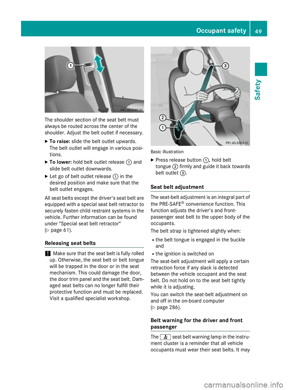
The shoulder section of the seat belt must
always be routed across the center of the
shoulder. Adjust the belt outlet if necessary. X
To raise: slide the belt outlet upwards.
The belt outlet will engage in various posi-
tions. X
To lower: hold belt outlet release �C and
slide belt outlet downwards. X
Let go of belt outlet release �C in the
desired position and make sure that the
belt outlet engages.
All seat belts except the driver's seat belt are
equipped with a special seat belt retractor to
securely fasten child restraint systems in the
vehicle. Further information can be found
under "Special seat belt retractor"
( Y
page 61).
Releasing seat belts
! Make sure that the seat belt is fully rolled
up. Otherwise, the seat belt or belt tongue
will be trapped in the door or in the seat
mechanism. This could damage the door,
the door trim panel and the seat belt. Dam-
aged seat belts can no longer fulfill their
protective function and must be replaced.
Visit a qualified specialist workshop. Basic illustration X
Press release button �C , hold belt
tongue �D firmly and guide it back towards
belt outlet �
Page 60 of 462
Deployment of Emergency Tensioning
Device s an d air bags
Important safet y notes
G WARNING
The air bag parts are hot after an air bag has
bee n deployed . There is a ris k of injury.
Do no t touch th e air bag parts . Hav e a
deployed air bag replaced at a qualified spe -
cialis t workshop as soo n as possible.
G WARNING
A deployed air bag no longer offers any pro -
tection and canno t provid e th e intended pro -
tection in an accident. There is an increase d
ris k of injury.
Hav e th e vehicle towed to a qualified special-
ist workshop in order to hav e a deployed air
bag replaced.
It is important fo r your safet y and that of your
passenger to hav e deployed air bags replaced
and to hav e any malfunctionin g air bags
repaired. Thi s will hel p to mak e sur e th e air
bags continue to perform their protective
function fo r th e vehicle occupant s in th e
event of a crash .
G WARNING
Pyrotechnic Emergency Tensioning Devices
that hav e bee n deployed are no longer opera-
tional and are unable to perform their inten-
ded protective function . Thi s poses an
increase d ris k of injury or eve n fatal injury.
Therefore, hav e pyrotechni c Emergency Ten -
sioning Devices whic h hav e bee n triggere d
immediately replaced at a qualified specialis t
workshop .
An electric moto r is used by PRE-SAF E ®
to
trigger th e tightenin g of th e seat belt in haz -
ardous situations. Thi s procedur e is reversi-
ble.
If Emergency Tensioning Devices are trig-
gered or air bags are deployed , you will hear a
bang, and a small amount of powder may also be released. The �u restrain t system warn -
in g lamp lights up.
Only in rar e cases will th e ban g affec t your
hearing. The powder that is release d gener-
ally doe s no t constitute a health hazard , but it
may caus e short-term breathin g difficulties in
people wit h asthm a or other respirator y prob-
lems. To avoid this, you may wish to get out of
th e vehicle or ope n th e windows as soo n as it
is saf e to do so.
Ai r bags and pyrotechni c Emergency Tension-
in g Devices (ETDs) contain perchlorat e mate-
rial , whic h may require special handlin g a nd
re gard fo r th e environment. National guide-
lines mus t be observed durin g disposal. In
California, see www.dtsc.ca.gov/
HazardousWaste/Perchlorate/
index.cfm .
Method of operation Durin g th e first stage of a collision , th e
restrain t system contro l uni t evaluates impor -
tant physical dat a relatin g to vehicle deceler -
ation or acceleration , suc h as:R
duration R
direction R
intensit y
Based on th e evaluation of this data, th e
restrain t system contro l uni t triggers th e
Emergency Tensioning Devices durin g a fron -
ta l or rea r collision .
An Emergency Tensioning Devic e can only be
triggered, if: R
th e ignition is switched on R
th e component s of th e restrain t system are
operational; see "Restrain t system warnin g
lamp " ( Y
page 45) R
th e belt tongue is engage d in th e buckl e on
th e respective front-passenger seat
The Emergency Tensioning Devices in th e
rea r compartmen t are triggere d independ -
entl y of th e loc k status of th e seat belts.
If th e restrain t system contro l uni t detects a
more severe accident, further component s of58
Occupant safety
Safety
Page 64 of 462
Stop the vehicle immediately, paying atten-
tion to road and traffic conditions. Reactivate
the special seat belt retractor and secure the
child restraint system properly.
All seat belts in the vehicle, except the driv-
er's seat belt, are equipped with a special seat
belt retractor. When activated, the special
seat belt retractor ensures that the seat belt
cannot slacken once the child seat is secured.
Installing a child restraint system: X
Make sure you observe the child restraint
system manufacturer's installation instruc-
tions. X
Pull the seat belt smoothly from the belt
outlet. X
Engage seat belt tongue in belt buckle.
Activating the special seat belt retractor: X
Pull the seat belt out fully and let the inertia
reel retract it again.
While the seat belt is retracting, you should
hear a ratcheting sound. The special seat
belt retractor is enabled. X
Push the child restraint system down so
that the seat belt is tight and does not
loosen.
Removing the child restraint system and
deactivating the special seat belt retractor: X
Make sure you observe the child restraint
system manufacturer's installation instruc-
tions. X
Press the release button of the seat belt
buckle and guide the seat belt tongue back
towards the belt sash guide.
The special seat belt retractor is deactiva-
te d .
Child restraint system
The use of seat belts and child restraint sys-
tems is required by law in: R
all 50 states R
the U.S. territories R
the District of Columbia R
all Canadian provinces
If you install a rearward-facing child restraint
system on the center rear seat, the rear arm
rest must be folded back as far as possible.
You can obtain further information about the
correct child restraint system from any
authorized Mercedes-Benz Center.
G WARNING
If the child restraint system is installed incor-
rectly on a suitable seat, it cannot protect as
intended. The child cannot then be restrained
in the event of an accident, heavy braking or
sudden changes of direction. There is an
increased risk of injury, possibly even fatal.
Make sure that you observe the child restraint
system manufacturer's installation instruc-
tions and the notes on use. Please ensure,
that the base of the child restraint system is
always resting completely on the seat cush-
ion. Never place objects, e.g. cushions, under
or behind the child restraint system. Only use
child restraint systems with the original cover
designed for them. Only replace damaged
covers with genuine covers.
G WARNING
If the child restraint system is installed incor-
rectly or is not secured, it can come loose in
the event of an accident, heavy braking or a
sudden change in direction. The child
restraint system could be thrown about, strik-
ing vehicle occupants. There is an increased
risk of injury, possibly even fatal.
Always install child restraint systems prop-
erly, even if they are not being used. Make
sure that you observe the child restraint sys-
tem manufacturer's installation instructions.
You will find further information on stowing
objects, luggage or loads under "Loading
guidelines" ( Y
page 340).
G WARNING
Child restraint systems or their securing sys-
tems which have been damaged or subjected62
Children in the vehicle
Safety
Page 94 of 462
You could therefore be locked out if: R
the vehicle is being pushed. R
the vehicle is being towed. R
the vehicle is on a roller dynamometer.
You can also switch the automatic locking
function on and off using the on-board com-
puter ( Y
page 285).
Power closingPower closing pulls the doors and trunk lid
into their locks automatically even if they are
only partly closed. X
To power close a door: push the door into
the lock up to the first detent position.
Power closing will pull the door fully closed. X
To power close the tailgate: lightly press
the tailgate downwards.
Power closing will pull the tailgate fully
closed.
Unlocking the driver's door (mechan-
ical key)
If the vehicle can no longer be locked or
unlocked with the SmartKey or KEYLESS-GO,
use the mechanical key.
If you use the mechanical key to unlock and
open the driver's door, the anti-theft alarm
system will be triggered ( Y
page 78).X
Take the mechanical key out of the Smart-
Key ( Y
page 85).X
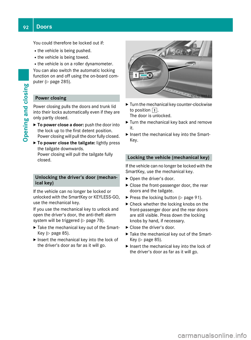
Insert the mechanical key into the lock of
the driver's door as far as it will go. X
Turn the mechanical key counter-clockwise
to position �G .
The door is unlocked. X
Turn the mechanical key back and remove
it. X
Insert the mechanical key into the Smart-
Key.
Locking the vehicle (mechanical key) If the vehicle can no longer be locked with the
SmartKey, use the mechanical key. X
Open the driver's door. X
Close the front-passenger door, the rear
doors and the tailgate. X
Press the locking button ( Y
page 91).X
Check whether the locking knobs on the
front-passenger door and the rear doors
are still visible. Press down the locking
knobs by hand, if necessary. X
Close the driver's door. X
Take the mechanical key out of the Smart-
Key ( Y
page 85). X
Insert the mechanical key into the lock of
the driver's door as far as it will go.92
Doors
Opening and closing
Page 134 of 462

X
To switch on: turn the light switch to �` .
The green �` indicator lamp in the instru-
ment cluster lights up.
Standing lamps
Switching on the standing lamps ensures the
corresponding side of the vehicle is illumina-
ted. X
To switch on the standing lamps: the
SmartKey is not in the ignition lock or it is in
position 0 .X
Turn the light switch to �c (left-hand side
of the vehicle) or �d (right-hand side of
the vehicle).
Vehicles towing a trailer: both the right and
left standing lamps (tail lamps) are always
illuminated on the trailer.
Combination switch
Turn signal
�C
High-beam headlamps�D
Turn signal, right�