2016 MERCEDES-BENZ G-Class ECU
[x] Cancel search: ECUPage 252 of 302

iWhen re-installing trim panel?, make sure
that retainer Aengages in recess B.
Removing the spare wheel
The spare wheel is heavy. Take particular note of
this when removing the spare wheel.
XRemove wheel nuts :.
XRemove the spare wheel.
Mounting the wheel
After changing a wheel:
XRepair or replace the damaged wheel as soon
as possible and secure the spare wheel in
place again.
XSecure the damaged wheel on the spare
wheel bracket with wheel nuts :. When
doing so, make sure that the wheel cannot
come loose.
XWhen re-installing trim panel ?, make sure
that retainer Bengages in recess A
(
Ypage 249).
XMake sure that tab ;is below when re-
installing cover ring :(Ypage 249).
XFor safety reasons, regularly check to ensure
that the wheel is securely fastened.
Flat tire
Preparing the vehicle
XStop the vehicle on solid, non-slippery and
level ground, as far away as possible from
traffic.
XSwitch on the hazard warning lamps
(Ypage 89).
XApply the parking brake.
XBring the front wheels into the straight-ahead
position.
XMove the selector lever to position P.
XSwitch off the engine.
XRemove the SmartKey from the ignition lock.
The steering wheel lock stays active for as
long as the SmartKey is removed.
XAll occupants must get out of the vehicle.
Make sure that they are not endangered as
they do so.
XMake sure that no one is near the danger area
while a wheel is being changed. Anyone who
is not directly assisting in the wheel change
should, for example, stand behind the barrier.
XGet out of the vehicle. Pay attention to traffic
conditions when doing so.
XClose the driver's door.
Battery (vehicle)
Important safety notes
Special tools and expert knowledge are required
when working on the battery, e.g. removal and
installation. You should therefore have all work
involving the battery carried out at a qualified
specialist workshop.
GWARNING
Work carried out incorrectly on the battery
can lead, for example, to a short circuit and
thus damage the vehicle electronics. This can
lead to function restrictions applying to
safety-relevant systems, e.g the lighting sys-
tem, the ABS (anti-lock braking system) or the
ESP
®(Electronic Stability Program). The oper-
ating safety of your vehicle may be restricted.
You could lose control of the vehicle, for
example:
Rwhen braking
Rin the event of abrupt steering maneuvers
and/or when the vehicle's speed is not
adapted to the road conditions
There is a risk of an accident.
In the event of a short circuit or a similar inci-
dent, contact a qualified specialist workshop
immediately. Do not drive any further. You
250Battery (vehicle)
Breakdown assistance
Page 253 of 302

should have all work involving the battery car-ried out at a qualified specialist workshop.
If ABS malfunctions, the wheels can lock during braking. This limits the steerability of the vehicle
when braking and may increase the braking dis-
tance.
If ESP
®malfunctions, the vehicle will not be sta-
bilized if it starts to skid or a wheel starts to spin.
iFor further information about ABS and
ESP®, see (Ypage 55) and (Ypage 57).
GWARNING
During the charging process, a battery produ-
ces hydrogen gas. If a short circuit occurs or
sparks are created, the hydrogen gas can
ignite. There is a risk of an explosion.
RMake sure that the positive terminal of a
connected battery does not come into con- tact with vehicle parts.
RNever place metal objects or tools on a bat-
tery.
RIt is important that you observe the descri-
bed order of the battery terminals when
connecting and disconnecting a battery.
RWhen jump-starting, make sure that the
battery poles with identical polarity are
connected.
RIt is particularly important to observe the
described order when connecting and dis-
connecting the jumper cables.
RNever connect or disconnect the battery
terminals while the engine is running.
GWARNING
Electrostatic build-up can lead to the creation of sparks, which could ignite the highly explo-
sive gases of a battery. There is a risk of an
explosion.
Before handling the battery, touch the vehicle
body to remove any existing electrostatic
build-up.
The highly flammable gas mixture forms when
charging the battery as well as when jump-start-
ing. Always make sure that neither you nor the bat-
tery is electrostatically charged. A build-up of
electrostatic charge can be caused, for exam-
ple:
Rby wearing clothing made from synthetic
fibers
Rdue to friction between clothing and seats
Rif you push or pull the battery across the car-
pet or other synthetic materials
Rif you wipe the battery with a cloth
GWARNING
Battery acid is caustic. There is a risk of injury.
Avoid contact with skin, eyes or clothing. Do
not inhale any battery gases. Do not lean over
the battery. Keep children away from batter-
ies. Wash away battery acid immediately with
plenty of clean water and seek medical atten-
tion.
!Have the battery checked regularly at a
qualified specialist workshop.
Observe the service intervals in the Mainte-
nance Booklet or contact a qualified specialist
workshop for more information.
!You should have all work involving the bat-
tery carried out at a qualified specialist work-
shop. In the exceptional case that it is neces-
sary for you to disconnect the battery your-
self, make sure that:
Ryou switch off the engine and remove the
SmartKey. Check that all the indicator
lamps in the instrument cluster are off.
Otherwise, electronic components, such as
the alternator, may be damaged.
Ryou first remove the negative terminal
clamp and then the positive terminal
clamp. Never swap the terminal clamps.
Otherwise, the vehicle's electronic system
may be damaged.
Ron vehicles with automatic transmission,
the transmission is locked in position P
after disconnecting the battery. The vehicle
is secured against rolling away. You can
then no longer move the vehicle.
The battery and the cover of the positive ter-
minal clamp must be installed securely during
operation.
Battery (vehicle)251
Breakdown assistance
Z
Page 258 of 302

XLift up cover:of positive terminal ;in the direction of the arrow.
XConnect positive terminal ;on your vehicle to positive terminal ?of donor battery Busing the
jumper cable. beginning with your own battery.
XStart the engine of the donor vehicle and run it at idling speed.
XConnect negative terminal Aof donor battery Bto ground point =of your vehicle using the
jumper cable, connecting the jumper cable to donor battery Bfirst.
XStart the engine.
XFirst, remove the jumper cables from ground point =and negative terminal A, then from pos-
itive clamp ;and positive terminal ?. Each time beginning with your vehicle's battery.
XHave the battery checked at a qualified specialist workshop.
iJump-starting is not considered to be a normal operating condition.
iJumper cables and further information regarding jump-starting can be obtained at any qualified
specialist workshop.
Towing and tow-starting
Important safety notes
GWARNING
Functions relevant to safety are restricted or
no longer available if:
Rthe engine is not running.
Rthe brake system or the power steering is
malfunctioning.
Rthere is a malfunction in the voltage supply or the vehicle's electrical system.
If your vehicle is being towed, much more
force may be necessary to steer or brake.
There is a risk of an accident.
In such cases, use a tow bar. Before towing,
make sure that the steering moves freely.
GWARNING
When towing or tow-starting another vehicle
and its weight is greater than the permissible
gross weight of your vehicle, the:
Rthe towing eye could detach itself
Rthe vehicle/trailer combination could roll-
over.
There is a risk of an accident.
When towing or tow-starting another vehicle,
its weight should not be greater than the per- missible gross weight of your vehicle.
!If DISTRONIC PLUS or the HOLD function is
activated, the vehicle brakes automatically in
certain situations. To prevent damage to the
vehicle, deactivate DISTRONIC PLUS and the
HOLD function in the following or other simi-
lar situations:
Rwhen towing the vehicle
Rin the car wash
!The vehicle can be towed a maximum of
30 miles (50km). The towing speed of 30 mph
(50 km/h) must not be exceeded.
If the vehicle has to be towed more than
30 miles (50km), the entire vehicle must be
raised and transported.
!Only secure the tow cable or tow bar to the
towing eyes. You could otherwise damage the
vehicle.
!Do not tow with sling-type equipment. This
could damage the vehicle.
!Do not use the towing eyes for recovery pur-
poses as this could damage the vehicle. If in
doubt, recover the vehicle with a crane.
!When towing, pull away slowly and
smoothly. If the tractive power is too high, the
vehicles could be damaged.
!Your vehicles is equipped with an automatic
transmission. Therefore, you must not have
the vehicle tow-started. The transmission
may otherwise be damaged.
iDetails on the permissible gross vehicle
weight of your vehicle can be found on the
vehicle identification plate (
Ypage 288).
256Towing and tow-starting
Breakdown assistance
Page 260 of 302

Transporting the vehicle
4MATIC vehicles/vehicles with auto-
matic transmission
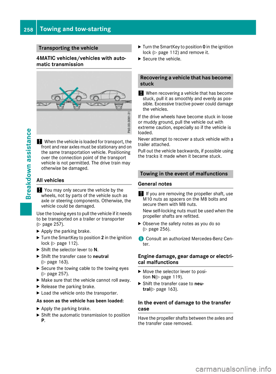
!When the vehicle is loaded for transport, the
front and rear axles must be stationary and on the same transportation vehicle. Positioning
over the connection point of the transport
vehicle is not permitted. The drive train may
otherwise be damaged.
All vehicles
!You may only secure the vehicle by the
wheels, not by parts of the vehicle such as
axle or steering components. Otherwise, the
vehicle could be damaged.
Use the towing eyes to pull the vehicle if it needs
to be transported on a trailer or transporter
(
Ypage 257).
XApply the parking brake.
XTurn the SmartKey to position 2in the ignition
lock (Ypage 112).
XShift the selector lever to N.
XShift the transfer case toneutral
(Ypage 163).
XSecure the towing cable to the towing eyes
(Ypage 257).
XMake sure that the vehicle cannot roll away.
XRelease the parking brake.
XLoad the vehicle onto the transporter.
As soon as the vehicle has been loaded:
XApply the parking brake.
XShift the automatic transmission to position
P .
XTurn the SmartKey to position 0in the ignition
lock (Ypage 112) and remove it.
XSecure the vehicle.
Recovering a vehicle that has become
stuck
!
When recovering a vehicle that has become
stuck, pull it as smoothly and evenly as pos-
sible. Excessive tractive power could damage
the vehicles.
If the drive wheels have become stuck in loose
or muddy ground, pull the vehicle out with
extreme caution, especially so if the vehicle is
loaded.
Never attempt to recover a stuck vehicle with a
trailer attached.
Pull out the vehicle backwards, if possible using the tracks it made when it became stuck.
Towing in the event of malfunctions
General notes
!If you are removing the propeller shaft, use
M10 nuts as spacers on the M8 bolts and
secure them with M8 nuts.
New self-locking nuts must be used when the
propeller shafts are refitted.
XObserve the safety notes as you do so
(Ypage 256).
iConsult an authorized Mercedes-Benz Cen-
ter.
Engine damage, gear damage or electri-
cal malfunctions
XMove the selector lever to posi-
tion N(Ypage 119).
XShift the transfer case to neu-
tral (Ypage 163).
In the event of damage to the transfer
case
Have the propeller shafts between the axles and
the transfer case removed.
258Towing and tow-starting
Breakdown assistance
Page 270 of 302

Maximum tire pressures
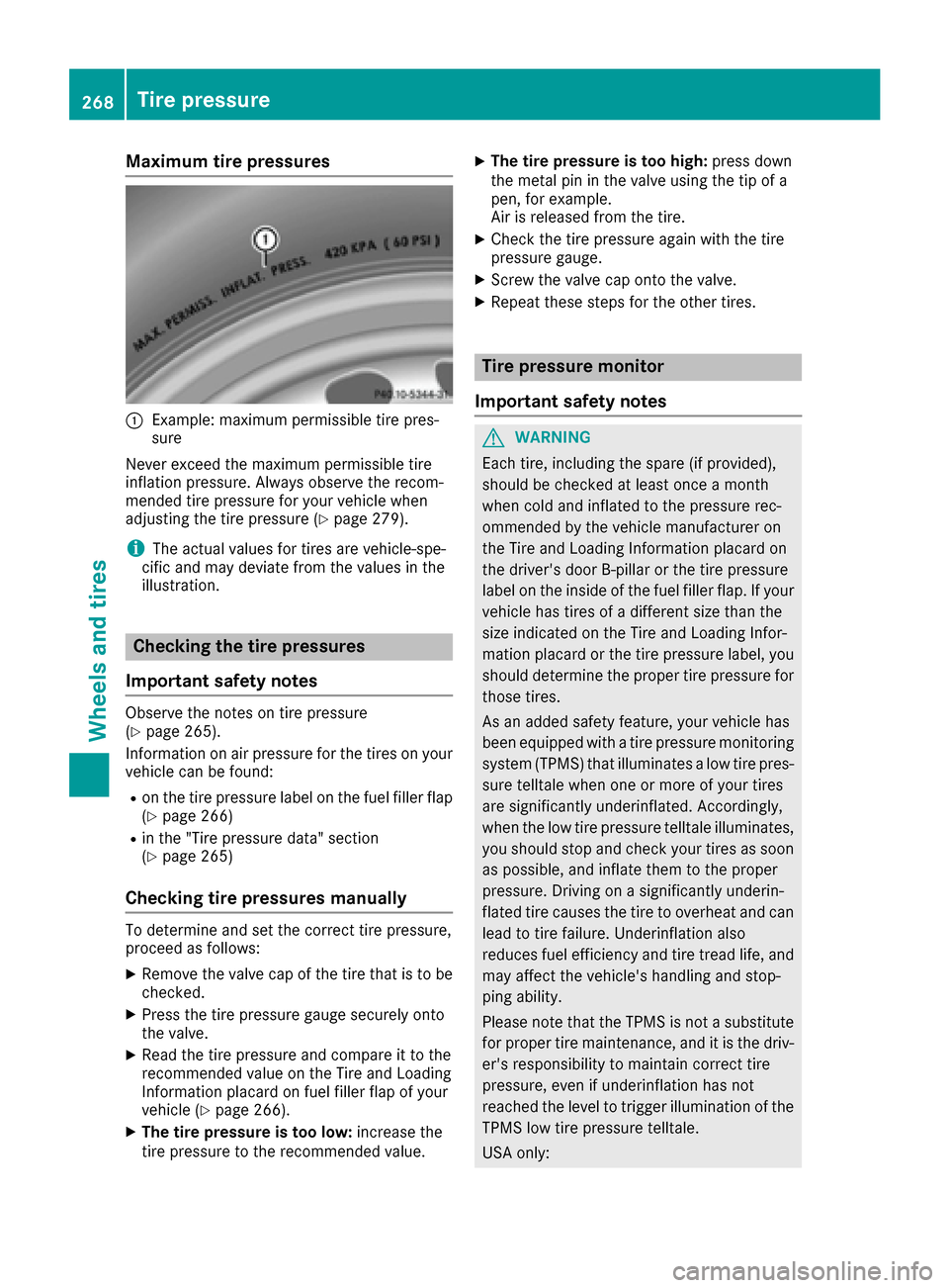
:Example: maximum permissible tire pres-
sure
Never exceed the maximum permissible tire
inflation pressure. Always observe the recom-
mended tire pressure for your vehicle when
adjusting the tire pressure (
Ypage 279).
iThe actual values for tires are vehicle-spe-
cific and may deviate from the values in the
illustration.
Checking the tire pressures
Important safety notes
Observe the notes on tire pressure
(Ypage 265).
Information on air pressure for the tires on your
vehicle can be found:
Ron the tire pressure label on the fuel filler flap
(Ypage 266)
Rin the "Tire pressure data" section
(Ypage 265)
Checking tire pressures manually
To determine and set the correct tire pressure,
proceed as follows:
XRemove the valve cap of the tire that is to be
checked.
XPress the tire pressure gauge securely onto
the valve.
XRead the tire pressure and compare it to the
recommended value on the Tire and Loading
Information placard on fuel filler flap of your
vehicle (
Ypage 266).
XThe tire pressure is too low: increase the
tire pressure to the recommended value.
XThe tire pressure is too high: press down
the metal pin in the valve using the tip of a
pen, for example.
Air is released from the tire.
XCheck the tire pressure again with the tire
pressure gauge.
XScrew the valve cap onto the valve.
XRepeat these steps for the other tires.
Tire pressure monitor
Important safety notes
GWARNING
Each tire, including the spare (if provided),
should be checked at least once a month
when cold and inflated to the pressure rec-
ommended by the vehicle manufacturer on
the Tire and Loading Information placard on
the driver's door B-pillar or the tire pressure
label on the inside of the fuel filler flap. If your
vehicle has tires of a different size than the
size indicated on the Tire and Loading Infor-
mation placard or the tire pressure label, you
should determine the proper tire pressure for
those tires.
As an added safety feature, your vehicle has
been equipped with a tire pressure monitoring
system (TPMS) that illuminates a low tire pres-
sure telltale when one or more of your tires
are significantly underinflated. Accordingly,
when the low tire pressure telltale illuminates,
you should stop and check your tires as soon
as possible, and inflate them to the proper
pressure. Driving on a significantly underin-
flated tire causes the tire to overheat and can lead to tire failure. Underinflation also
reduces fuel efficiency and tire tread life, and
may affect the vehicle's handling and stop-
ping ability.
Please note that the TPMS is not a substitute
for proper tire maintenance, and it is the driv-
er's responsibility to maintain correct tire
pressure, even if underinflation has not
reached the level to trigger illumination of the
TPMS low tire pressure telltale.
USA only:
268Tire pressure
Wheels and tires
Page 273 of 302

XMake sure that the SmartKey is in position2
in the ignition lock (Ypage 112).
XPress the =or; button on the steering
wheel to select the Serv.menu.
XPress the9or: button to select
Tire Pressure.
XPress the abutton.
The multifunction display shows the current
tire pressure for the individual tires or the
Tire pressure will be displayed
after driving a few minutesmessage.
XPress the :button.
The UseCurrentPressuresasNewRef‐erenceValuesmessage appears in the mul-
tifunction display.
If you wish to confirm the restart:
XPress the abutton.
The TirePress.MonitorRestartedmes-
sage appears in the multifunction display.
After driving for a few minutes, the system
checks whether the current tire pressures are
within the specified range. The new tire pres-
sures are then accepted as reference values
and monitored.
If you wish to cancel the restart:
XPress the %button.
The tire pressure values stored at the last
restart will continue to be monitored.
Loading the vehicle
Instruction labels for tires and loads
GWARNING
Overloaded tires can overheat, causing a
blowout. Overloaded tires can also impair the steering and driving characteristics and lead
to brake failure. There is a risk of accident.
Observe the load rating of the tires. The load
rating must be at least half of the GAWR of
your vehicle. Never overload the tires by
exceeding the maximum load.
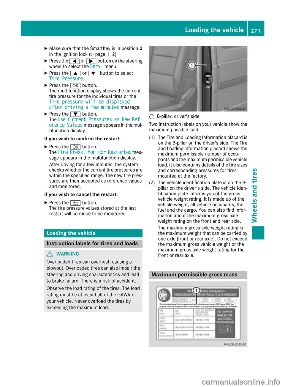
:B-pillar, driver's side
Two instruction labels on your vehicle show the
maximum possible load.
(1) The Tire and Loading Information placard is on the B-pillar on the driver's side. The Tire
and Loading Information placard shows the
maximum permissible number of occu-
pants and the maximum permissible vehicle
load. It also contains details of the tire sizes
and corresponding pressures for tires
mounted at the factory.
(2) The vehicle identification plate is on the B- pillar on the driver's side. The vehicle iden-
tification plate informs you of the gross
vehicle weight rating. It is made up of the
vehicle weight, all vehicle occupants, the
fuel and the cargo. You can also find infor-
mation about the maximum gross axle
weight rating on the front and rear axle.
The maximum gross axle weight rating is
the maximum weight that can be carried by
one axle (front or rear axle). Do not exceedthe maximum gross vehicle weight or the
maximum gross axle weight rating for the
front or rear axle.
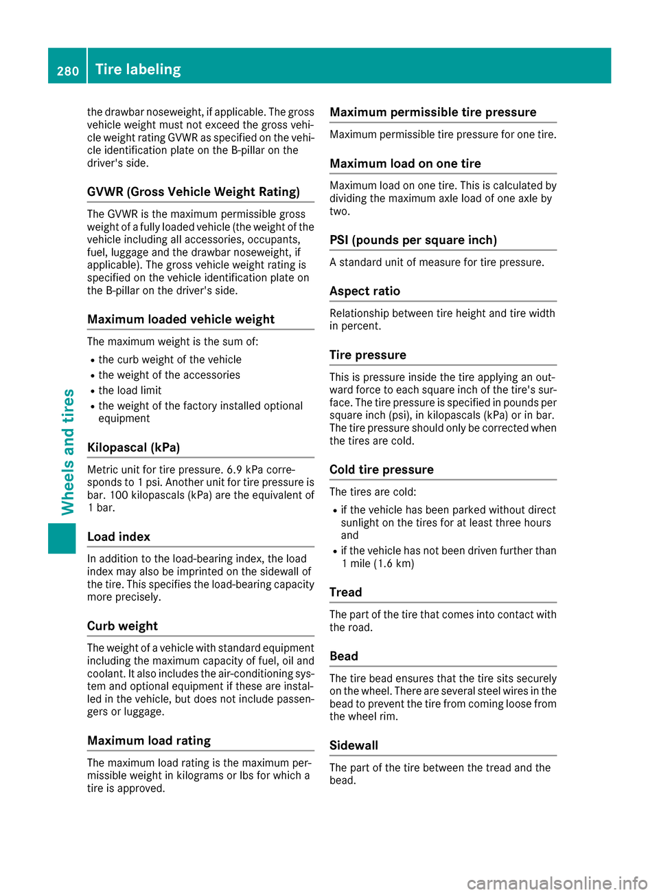
Maximum permissible gross mass
Loading the vehicle271
Wheels and tires
Z
Page 282 of 302

the drawbar noseweight, if applicable. The gross
vehicle weight must not exceed the gross vehi-
cle weight rating GVWR as specified on the vehi-
cle identification plate on the B-pillar on the
driver's side.
GVWR (Gross Vehicle Weight Rating)
The GVWR is the maximum permissible gross
weight of a fully loaded vehicle (the weight of thevehicle including all accessories, occupants,
fuel, luggage and the drawbar noseweight, if
applicable). The gross vehicle weight rating is
specified on the vehicle identification plate on
the B-pillar on the driver's side.
Maximum loaded vehicle weight
The maximum weight is the sum of:
Rthe curb weight of the vehicle
Rthe weight of the accessories
Rthe load limit
Rthe weight of the factory installed optional
equipment
Kilopascal (kPa)
Metric unit for tire pressure. 6.9 kPa corre-
sponds to 1 psi. Another unit for tire pressure is
bar. 100 kilopascal s(kPa) are the equivalent of
1 bar.
Load index
In addition to the load-bearing index, the load
index may also be imprinted on the sidewall of
the tire. This specifies the load-bearing capacity
more precisely.
Curb weight
The weight of a vehicle with standard equipment
including the maximum capacity of fuel, oil and
coolant. It also includes the air-conditioning sys-
tem and optional equipment if these are instal-
led in the vehicle, but does not include passen-
gers or luggage.
Maximum load rating
The maximum load rating is the maximum per-
missible weight in kilograms or lbs for which a
tire is approved.
Maximum permissible tire pressure
Maximum permissible tire pressure for one tire.
Maximum load on one tire
Maximum load on one tire. This is calculated by
dividing the maximum axle load of one axle by
two.
PSI (pounds per square inch)
A standard unit of measure for tire pressure.
Aspect ratio
Relationship between tire height and tire width
in percent.
Tire pressure
This is pressure inside the tire applying an out-
ward force to each square inch of the tire's sur-
face. The tire pressure is specified in pounds per
square inch (psi), in kilopascals (kPa) or in bar.
The tire pressure should only be corrected when
the tires are cold.
Cold tire pressure
The tires are cold:
Rif the vehicle has been parked without direct
sunlight on the tires for at least three hours
and
Rif the vehicle has not been driven further than
1 mile (1.6 km)
Tread
The part of the tire that comes into contact with
the road.
Bead
The tire bead ensures that the tire sits securely
on the wheel. There are several steel wires in the
bead to prevent the tire from coming loose from
the wheel rim.
Sidewall
The part of the tire between the tread and the
bead.
280Tire labeling
Wheels and tires
Page 284 of 302

ted. Check the tire pressure and reactivate the
tire pressure monitor (Ypage 268)if necessary.
Direction of rotation
Tires with a specified direction of rotation have
additional benefits, e.g. if there is a risk of hydro-
planing. You will only gain these benefits if the
correct direction of rotation is observed.
An arrow on the sidewall of the tire indicates its
correct direction of rotation.
You may mount the spare wheel against the
direction of rotation. Adhere to the time restric-
tion on use as well as the speed limitation speci-
fied on the spare wheel.
Storing wheels
Store tires that are not being used in a cool, dry
and preferably dark place. Protect the tires from
oil, grease, gasoline and diesel.
Mounting a wheel
Preparing the vehicle
GWARNING
When you remove the spare wheel from the
spare wheel bracket, the vehicle’s weight dis-
tribution changes. If the vehicle is already
raised, the jack could tip over. There is a risk
of injury.
Remove the spare wheel from the spare wheel
bracket before lifting the vehicle.
XPrepare the vehicle as described
(Ypage 250).
XRemove the vehicle tool kit and the jack
(Ypage 248).
XSecure the vehicle to prevent it from rolling
away.
XRemove the spare wheel from the spare wheel
bracket (Ypage 249).
iVehicles without a spare wheel or emer-
gency spare wheel are not equipped with a
tire-change tool kit at the factory. For more
information on which tools are required to
perform a wheel change on your vehicle e.g. lug wrench or jack, consult an authorized
Mercedes-Benz Center.
Securing the vehicle to prevent it from
rolling away
XOn level ground:
place chocks or other suit-
able items under the front and rear of the
wheel that is diagonally opposite the wheel
you wish to change.
XOn downhill gradients: place chocks or
other suitable items in front of the wheels of
the front and rear axle.
Raising the vehicle
GWARNING
If you do not position the jack correctly at the
appropriate jacking point of the vehicle, the
jack could tip over with the vehicle raised.
There is a risk of injury.
Only position the jack at the appropriate jack-
ing point of the vehicle. The base of the jack
must be positioned vertically, directly under
the jacking point of the vehicle.
!The jack is designed exclusively for jacking
up the vehicle at the jacking points. Other-
wise, your vehicle could be damaged.
Observe the following when raising the vehicle:
RTo raise the vehicle, only use the vehicle-spe-
cific jack that has been tested and approved
by Mercedes-Benz. If used incorrectly, the
jack could tip over with the vehicle raised.
RThe jack is designed only to raise and hold the
vehicle for a short time while a wheel is being
changed. It is not suited for performing main-
tenance work under the vehicle.
RAvoid changing the wheel on uphill and down- hill slopes.
RBefore raising the vehicle, secure it from roll-
ing away by applying the parking brake and
inserting wheel chocks. Do not disengage the
parking brake while the vehicle is raised.
RThe jack must be placed on a firm, flat and
non-slip surface. On a loose surface, a large,
load-bearing underlay must be used. On a
slippery surface, a non-slip underlay must be
used, e.g. rubber mats.
RDo not use wooden blocks or similar objects
as a jack underlay. Otherwise, the jack will not
282Changing a wheel
Wheels and tires