Page 121 of 557
Using
the cigar ette lighter &
WARNING ‑ Risk of fire and injury from
th e hot cigar ette lighter
Yo u can burn yourself if youto uch the hot
heating element or the soc ket of the ciga‐
re tte lighter.
In addition, flammable materials may ignite
if:
R you drop the hot cigar ette lighter
R ach ild holds the hot cigar ette lighter to
objects, forex ample #
Alw ays hold the cigar ette lighter bythe
knob. #
Alw ays make sure that the cigar ette
lighter is out of reach of children. #
Never lea vechildren unat tended in the
ve hicle. #
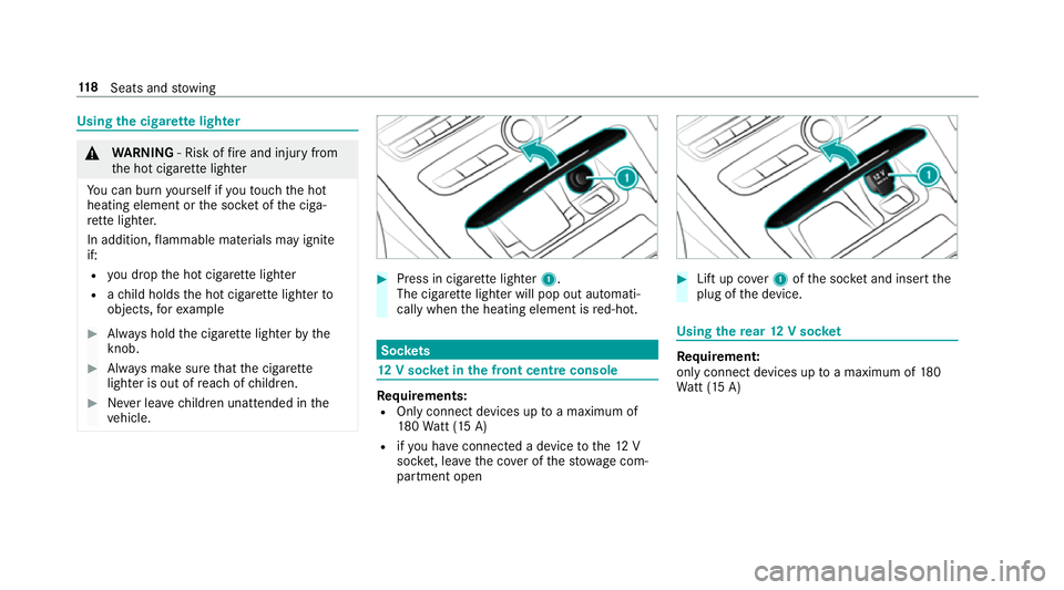
Press in cigar ette lighter 1.
The cigar ette lighter will pop out automati‐
cally when the heating element is red-hot. Soc
kets 12
V so cket inthe front centre console Re
quirements:
R Only connect devices up toa maximum of
18 0Wa tt (15 A)
R ifyo u ha veconnected a device tothe12 V
soc ket, le aveth e co ver of thestow age com‐
partment open #
Lift up co ver1 ofthe soc ket and insert the
plug of the device. Using
there ar 12 V so cket Re
quirement:
only connect devices up toa maximum of 180
Wa tt (15 A) 11 8
Seats and stowing
Page 122 of 557
#
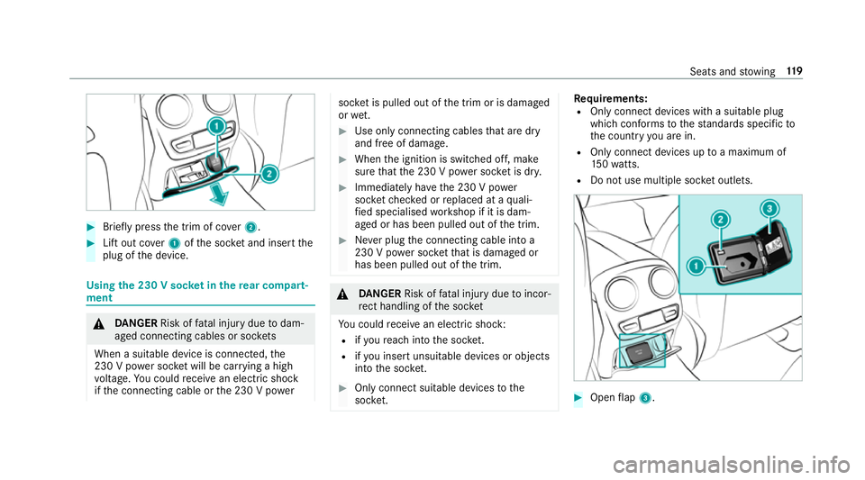
Brief lypress the trim of co ver2. #
Lift out co ver1 ofthe soc ket and insert the
plug of the device. Using
the 230 V soc ket in the rear comp art‐
ment &
DANG ER Risk of fata l injury due todam‐
aged connecting cables or soc kets
When a suitable device is connected, the
230 V power soc ket will be car rying a high
vo ltage. You could recei vean electric shock
if th e connecting cable or the 230 V po wer soc
ket is pulled out of the trim or is damaged
or we t. #
Use only connecting cables that are dry
and free of damage. #
When the ignition is switched off, make
sure that the 230 V po wer soc ket is dr y. #
Immedia tely ha ve the 230 V po wer
soc ketch ecked or replaced at a quali‐
fi ed specialised workshop if it is dam‐
aged or has been pulled out of the trim. #
Never plug the connecting cable into a
230 V po wer soc ketth at is damaged or
has been pulled out of the trim. &
DANG ER Risk of fata l injury due toincor‐
re ct handling of the soc ket
Yo u could recei vean electric shock:
R ifyo ure ach into the soc ket.
R ifyo u insert unsuitable devices or objects
into the soc ket. #
Only connect suitable devices tothe
soc ket. Re
quirements:
R Only connect devices with a suitable plug
which con form sto thest andards specific to
th e count ryyou are in.
R Only connect devices uptoa maximum of
15 0wa tts.
R Do not use multiple soc ket outlets. #
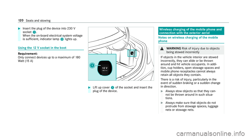
Open flap 3. Seats and
stowing 11 9
Page 123 of 557
#
Insert the plug of the device into 230 V
soc ket1.
When the on-board electrical sy stem voltage
is suf ficient, indicator la mp2lights up. Using
the12 V so cket inthe boot Re
quirement:
Only connect devices up toa maximum of 180
Wa tt (15 A) #
Lift up co ver1 ofthe soc ket and insert the
plug of the device. Wire
lesscharging of the mobile phone and
connection with theex terior aerial Note
s on wireless charging of the mobile
phone &
WARNING Risk of inju rydue toobjects
being stowed inco rrectly
If objects in theve hicle interior are stowed
incor rectly, they can slide or be thrown
around and hit vehicle occupants. In addi‐
tion, cup holders, open stowage spaces and
mobile phone recep tacles cannot al ways
re tain all objects they contain.
The reis a risk of injur y,particularly in the
ev ent of sudden braking or a sudden change
in direction. #
Alw aysstow objects so that they can‐
not be throw n around in su chsitua‐
tions. #
Alw ays make sure that objects do not
pr otru de from stowage spaces, luggage
nets or stowage nets. 12 0
Seats and stowing
Page 124 of 557
#
Close the loc kable stow age spaces
before starting a journe y. #
Alw aysstow and secure heavy, hard,
poin ted, sharp-edged, fragile or bulky
objects in the boot/load compartment. Obser
vethe no tes on loading theve hicle. &
WARNING Risk offire from placing
objects in the mobile phone stowage
compartment
If yo u place objects in the mobile phone
stow age compartment, they may heat up
exc essively and even catch fire. #
Do not place additional objects, espe‐
cially those mode of me tal, in the
mobile phone stowage compartment. *
NO
TEDama getoobjects caused by
placing them in the mobile phone stow‐
age compartment If
yo u place objects in the mobile phone
stow age compartment, these may be dam‐
aged byelectromagnetic fields. #
Do not place credit cards, storage
media or other objects sensitive to
electromagnetic fields in the mobile
phone stowage compartment. *
NO
TEDama getothe mobile phone
stow age compartment caused byliquids If liquid is spilled in
the mobile phone stow‐
age compartment, the mobile phone stowage
compartment may be damaged. #
Do not spill liquids into the mobile
phone stowage compartment. R
Depending on theve hicle equipment, the
mobile phone is connected totheve hicle's
ex terior aerial via thech arging module. R
The charging function and wireless connec‐
tion of the mobile phone totheve hicle's
ex terior aerial are only available if the ignition
is switched on.
R Small mobile phones may not be able tobe
ch arge d in everyposition of the mobile
phone stowage compartment.
R Largemobile phones which do not rest flat in
th e mobile phone stowage compartment may
not be able tobe charge d or connec ted with
th eve hicle's exterior aerial.
R The mobile phone may heat up during the
ch arging process. The mobile phone can be
cooled in the mobile phone stowage com‐
partment when the air conditioning sy stem is
switched on. The cooling output in the
mobile phone stowage compartment is high‐
est when the controller in theglove box is
closed. Wire
lesscharging of the mobile phone Re
quirements:
R Your mobile phone must be suitable for wire‐
less charging (Qi-compatible mobile phone). Seats and
stowing 121
Page 125 of 557

Yo
u can find a li stof Qi-compatible mobile
phones online at:
http://www.mercedes-benz.com/connect
R Toensure more ef ficient charging and con‐
nection with theve hicle's exterior aerial,
re mo vethe pr otective co ver from the mobile
phone.
R If possible, use the mat when charging. #
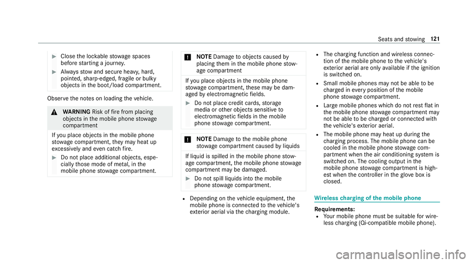
Place the mobile phone as close tothe
centre of mat 1as possible wi th the display
fa cing up wards.
The mobile phone is charge d automatically,
as is apparent from thewa y in which the mobile phone
reacts and from thech arging
symbol in the multimedia sy stem displa y.
Malfunctions during thech arging process are
shown in the multimedia sy stem displa y.
% Toclean, mat 1can be remo ved. Fi
tting/ removing floormats &
WARNING Risk of accident due to
objects in the driver's foot we ll
Objects in the driver's foot we ll may impede
pedal tr avel or block a depressed pedal.
This jeopardises the operating and road
saf ety of theve hicle. #
Stow all objects in theve hicle securely
so that they cannot getinto the driver's
fo ot we ll. #
Alw aysfit th efloor mats securely and
as prescribed in order toensure that
th ere is alw ays suf ficient room forthe
pedals. #
Do not use loose floor mats and do not
place floor mats on top of one ano ther. #
Tofit: press studs 1onto holders 2. #
Toremo ve:pull thefloor mat off the holders
2. 12 2
Seats and stowing
Page 128 of 557

g
Driver's seat and front passenger seat occu‐
pied
1 Driver's seat, front passenger seat and rear
seats occupied
2 Driver's seat, front passenger seat and rear
seats occupied, boot laden
3 Driver's seat and front passenger seat occu‐
pied and maximum permissible rear axle
load utilised #
Turn the headlamp range adjus terto the
position which cor responds tothe load con‐
dition of your vehicle. Operating
the light combination switch 1
Main beam
2 Turn signal light, right 3
Headlamp flashing
4 Turn signal light, left #
Pull or push the combination switch in the
re leva nt di rection following the ar row.
Switching on the main beam manually #
Vehicles with Adaptive Highbeam Assist
Plus: Turn the light switch totheL posi‐
tion. R Press the combination switch be yond the
pressure point in the direction of
ar ro w 1.
When the main beam is activated, the indicator
lamp for dipped beam is deactivated and
re placed bythe indicator lamp forth e main
beam. #
Toswitch off the main beam: movethe
combination switch ba cktoits starting posi‐
tion. #
Toindicate briefl y:press the combination
switch briefly up tothe pressure point in the
direction of ar row2or4.
The cor responding turn signal light flashes
th re e times. Light and sight
12 5
Page 246 of 557
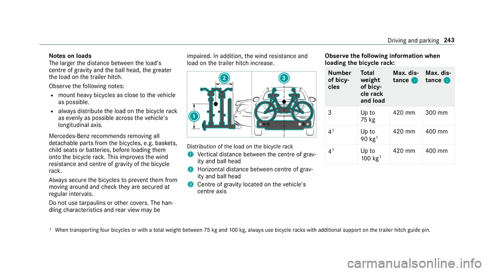
Note
s on loads
The larger the dis tance between the load's
cent reof gr avity and the ball head, the greater
th e load on the trailer hitch.
Obser vethefo llowing no tes:
R mount heavy bicycles as close totheve hicle
as possible.
R always distribute the load on the bicycle rack
as eve nly as possible across theve hicle's
longitudinal axis.
Mercedes-Benz recommends removing all
de tach able parts from the bicycles, e.g. bask ets,
ch ild seats or batteries, before loading them
onto the bicycle rack . This impr ovesth e wind
re sis tance and centre of gr avity of the bicycle
ra ck.
Alw ays secure the bicycles toprev ent them from
moving around and check they are secured at
re gular inter vals.
Do not use tarp aulins or other co vers. The han‐
dling characteristics and rear view may be impaired. In addition,
the wind resis tance and
load on the trailer hitch increase. Distribution of
the load on the bicycle rack
1 Vertical dis tance between the cent reof gr av‐
ity and ball head
2 Horizon tal dis tance between centre of gr av‐
ity and ball head
3 Cent reof gr avity located on theve hicle's
centre axis Obser
vethefo llowing information when
loading the bicycle rack: Nu
mber
of bicy‐
cles To
tal
we ight
of bicy‐
cle rack
and load Max. dis‐
tance
1 1Max. dis‐
tance
2 2
3U pto
75 kg 420 mm 300 mm
4 1
Upto
90 kg1 420 mm 400 mm
4 1
Upto
10 0kg 1 420 mm 400 mm 1
When transpo rting four bicycles or with a totalwe ight between 75kgand 100kg , alw ays use bicycle rack s with additional support on the trailer hitch guide pin. Driving and parking
243
Page 270 of 557
Command
Function
Light To
display light settings
Massage To
display massage settings
Engine data To
display engine data
Seats To
display seat adjustment settings
Consumption To
display the consum ption
Visualisation To
display visualisation LINGU
ATRO NIC 267