Page 115 of 557
#
Alw aysstow and secure such objects
outside of the box in the boot. #
Alw ays obser vethe maximum permitted
load of the EASY -PAC K boot box. #
Do not use the EASY -PAC K boot box
when there ar seats are folded for‐
wa rds. The maximum permitted load of
the EASY -PACK
boot box is 10kg.To prev ent the box from being
ove rloaded, the box floor lo wersonto the boot
fl oor when the load reaches appr oximately 5 kg. #
Pull the box out using handle 2. #
Toincrease the load capacit y:press the
centre of floor 1down wardsto the desired
position and box size. #
Toreduce the load capacity: press button
3. #
Tosto w:press the box in comple tely using
handle 2, until it loc ksin place. %
Obser vethe no tes on cleaning the EASY-
PA CK boot box (→ page376). 11 2
Seats and stowing
Page 116 of 557
Installing/removing
the EAS Y-PA CK bo otbox #
Toinstall: openrotating catch 6and turn it
outwards. #
Inse rtretainer 2of box 1into outer holes
3. #
Raise box 1and press hooks 5into rear
shelf 4. #
Turn rotating catch 6inwa rdsto thestop. #
Toremo ve:turn le ft-hand rotating catch 6
clo ckwise and right-hand rotating catch 6
anti-clo ckwise by90°. #
Lowe r box 1and pull it out of anchorages
4, then pull box 1backwards and out of
holes 3. Opening
thesto wage space under the boot
floor *
NO
TEDama getothe handle in the boot
fl oor If
th e handle in the boot is left pr otru ding,
th e handle may be damaged. #
Unhinge the handle before you close
th e boot lid and clip it in place. Seats and
stowing 11 3
Page 117 of 557

#
Pull handle 1up and hook it into rain
trough 2. At
taching thero of rack &
WARNING Risk of inju ryby ex ceeding
th e maximum roof load
When you load thero of, theve hicle centre of
gr av ity rises and the driving characteristics
ch ange.
If yo uexc eed the maximum roof load, the
driving characteristics, as well as thesteer‐
ing and braking, will be greatly impaired. #
Neverexc eed the maximum roof load
and adjust your driving style. Yo
u will find information on the maximum roof
load in the "Technical data" section.
Re quirements:
R Only use roof rack ste sted and appr ovedby
Mercedes-Benz.
R Make sure that you can raise the sliding sun‐
ro of fully and open the boot lid fully once the
ro of rack isfitted.
R The panoramic sliding sunroof cann otbe
opened if a roof rack isfitted. The panoramic sliding sunroof closes again au
tomatically
when it encounters resis tance. *
NO
TEDama getothe co vers The co
vers may be dama ged and scratched
when being opened. #
Do not use me tallic or hard objects. 11 4
Seats and stowing
Page 123 of 557

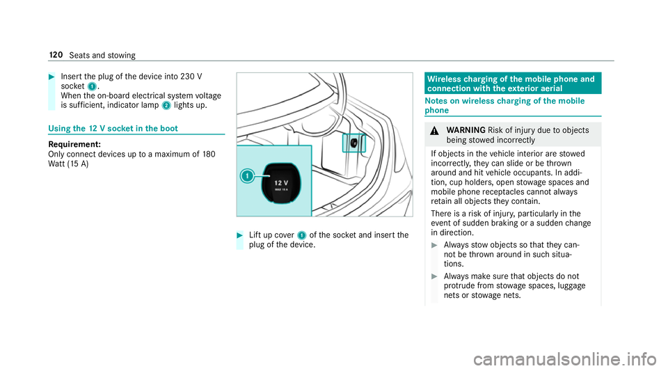
#
Insert the plug of the device into 230 V
soc ket1.
When the on-board electrical sy stem voltage
is suf ficient, indicator la mp2lights up. Using
the12 V so cket inthe boot Re
quirement:
Only connect devices up toa maximum of 180
Wa tt (15 A) #
Lift up co ver1 ofthe soc ket and insert the
plug of the device. Wire
lesscharging of the mobile phone and
connection with theex terior aerial Note
s on wireless charging of the mobile
phone &
WARNING Risk of inju rydue toobjects
being stowed inco rrectly
If objects in theve hicle interior are stowed
incor rectly, they can slide or be thrown
around and hit vehicle occupants. In addi‐
tion, cup holders, open stowage spaces and
mobile phone recep tacles cannot al ways
re tain all objects they contain.
The reis a risk of injur y,particularly in the
ev ent of sudden braking or a sudden change
in direction. #
Alw aysstow objects so that they can‐
not be throw n around in su chsitua‐
tions. #
Alw ays make sure that objects do not
pr otru de from stowage spaces, luggage
nets or stowage nets. 12 0
Seats and stowing
Page 124 of 557

#
Close the loc kable stow age spaces
before starting a journe y. #
Alw aysstow and secure heavy, hard,
poin ted, sharp-edged, fragile or bulky
objects in the boot/load compartment. Obser
vethe no tes on loading theve hicle. &
WARNING Risk offire from placing
objects in the mobile phone stowage
compartment
If yo u place objects in the mobile phone
stow age compartment, they may heat up
exc essively and even catch fire. #
Do not place additional objects, espe‐
cially those mode of me tal, in the
mobile phone stowage compartment. *
NO
TEDama getoobjects caused by
placing them in the mobile phone stow‐
age compartment If
yo u place objects in the mobile phone
stow age compartment, these may be dam‐
aged byelectromagnetic fields. #
Do not place credit cards, storage
media or other objects sensitive to
electromagnetic fields in the mobile
phone stowage compartment. *
NO
TEDama getothe mobile phone
stow age compartment caused byliquids If liquid is spilled in
the mobile phone stow‐
age compartment, the mobile phone stowage
compartment may be damaged. #
Do not spill liquids into the mobile
phone stowage compartment. R
Depending on theve hicle equipment, the
mobile phone is connected totheve hicle's
ex terior aerial via thech arging module. R
The charging function and wireless connec‐
tion of the mobile phone totheve hicle's
ex terior aerial are only available if the ignition
is switched on.
R Small mobile phones may not be able tobe
ch arge d in everyposition of the mobile
phone stowage compartment.
R Largemobile phones which do not rest flat in
th e mobile phone stowage compartment may
not be able tobe charge d or connec ted with
th eve hicle's exterior aerial.
R The mobile phone may heat up during the
ch arging process. The mobile phone can be
cooled in the mobile phone stowage com‐
partment when the air conditioning sy stem is
switched on. The cooling output in the
mobile phone stowage compartment is high‐
est when the controller in theglove box is
closed. Wire
lesscharging of the mobile phone Re
quirements:
R Your mobile phone must be suitable for wire‐
less charging (Qi-compatible mobile phone). Seats and
stowing 121
Page 128 of 557

g
Driver's seat and front passenger seat occu‐
pied
1 Driver's seat, front passenger seat and rear
seats occupied
2 Driver's seat, front passenger seat and rear
seats occupied, boot laden
3 Driver's seat and front passenger seat occu‐
pied and maximum permissible rear axle
load utilised #
Turn the headlamp range adjus terto the
position which cor responds tothe load con‐
dition of your vehicle. Operating
the light combination switch 1
Main beam
2 Turn signal light, right 3
Headlamp flashing
4 Turn signal light, left #
Pull or push the combination switch in the
re leva nt di rection following the ar row.
Switching on the main beam manually #
Vehicles with Adaptive Highbeam Assist
Plus: Turn the light switch totheL posi‐
tion. R Press the combination switch be yond the
pressure point in the direction of
ar ro w 1.
When the main beam is activated, the indicator
lamp for dipped beam is deactivated and
re placed bythe indicator lamp forth e main
beam. #
Toswitch off the main beam: movethe
combination switch ba cktoits starting posi‐
tion. #
Toindicate briefl y:press the combination
switch briefly up tothe pressure point in the
direction of ar row2or4.
The cor responding turn signal light flashes
th re e times. Light and sight
12 5
Page 136 of 557

R
Turn signal light: bulb, type PY 21W.
R The lighting sy stem is switched off.
R The co ver in the front wheel ar chhas been
re mo ved.
R The engine bonn etis open. 1
Dipped beam
2 Main beam/turn signal light #
Turn there leva nt housing co ver anti-clock‐
wise and remo veit. #
Main beam/dipped beam: turnthe soc ket
anti-clockwise and remo veit. #
Turn signal light: turnthe soc ket anti-clo ck‐
wise, unlock and remo veit. #
Pull the bulb out of the soc ket. #
Inse rtthe new bulb into the soc ket so that
th e entire base of the bulb is resting on the
bottom of the soc ket. #
Inse rtsoc ket and turn it clo ckwise. #
Press on the housing co ver and turn it clock‐
wise. #
Replace the co ver in the front wheel ar ch. Changing
there ar bulbs (vehicles with halo‐
ge n headla mps) Opening and closing
the side trim panels in
th e boot #
Toopen: release right-hand or left-hand side
trim panels 1atthe side and remo ve. #
Toclose: reinse rtside trim panel 1.
Re placing the tail lamp bulbs
Re quirements:
R Turn signal light: bulb, type PY 21W.
R Reversing light: bulb, type W 16W.
R The lighting sy stem is switched off. Light and sight
13 3
Page 137 of 557
R
The side trim panel in the boot is open. #
Press the upper and lo wer catch on the plug
to ge ther and remo vethe plug. #
Press tab1 outwards and remo vethe bulb
mount. #
Turn signal light: press bulb2gently into
th e bulb mount, turn it anti-clockwise and
re mo veit from the bulb mount. #
Insert the new bulb into the bulb mount and
turn it clockwise. #
Reversing light: pull bulb3out of the bulb
mount. #
Insert the new bulb into the bulb mount. #
Insert the bulb mount again. #
Insert the plug until the catch hooks engage
audibl y. #
Close the side trim panel. Wi
ndscreen wipers and windscreen washer
sy stem Switching
the windscreen wipers on/off #
1 í Single wipe/ îwiping with
wa sher fluid #
1gWi ndscreen wipers off #
2 Ä Intermittent wiping, normal 134
Light and sight