Page 10 of 557
1
Steering wheel gearshift paddle →
16 5
2 Combination swit ch →
12 5
3 DIRECT SELECT le ver →
16 2
4 Displ ay(multimedia sy stem) →
269
5 Start/ Stop button →
154
6 Control panel for multimedia sy stem →
269
7 Climate control sy stems →
14 2
8 Glovebox →
106
9 Haza rdwa rning lights →
12 6
A Stow age compartment →
106
B Controls forth e multimedia sy stem →
269
C Rear wind ow roller sunblind →
78
D ECO start/ stop function →
15 9
E Parking Pilot →
219
F Setting theve hicle le vel →
207 G
DYNA MIC SELECT switch →
161
H PASSENGER AIRB AGindicator lamp →
,41
I Control panel for multimedia sy stem →
24 5
J Toadjust thesteering wheel →
102
K Control panel for on-board computer →
24 5
L Cruise cont rol le ver →
191
M Tounlo ckthe bonn et →
365
N Electric parking brake →
176
O Light switch →
12 3
P Control panel for:
St eering Pilot →
203
Ac tive Lane Keeping Assist →
236
Pa rking Assist PARKTRONIC →
210
Head-up display →
256 At
aglance – Cockpit 7
Page 12 of 557
1
Displ ay(multimedia sy stem) →
269
2 Steering wheel gearshift paddle →
16 5
3 Combination swit ch →
12 5
4 DIRECT SELECT le ver →
16 2
5 Control panel for:
St eering Pilot →
203
Ac tive Lane Keeping Assist →
236
Pa rking Assist PARKTRONIC →
210
Head-up display →
256
6 Light switch →
12 3
7 Electric pa rking brake →
176
8 Tounlo ckthe bonn et →
365
9 Control panel for multimedia sy stem →
24 5
A Toadjust thesteering wheel →
102
B Control panel for on-board computer →
24 5 C
Cruise cont rol le ver →
191
D Haza rdwa rning lights →
12 6
E DYNA MIC SELECT switch →
161
F Toset theve hicle le vel →
207
G Parking Pilot →
219
H ECO start/ stop function →
15 9
I Rear wind ow roller sunblind →
78
J Controls forth e multimedia sy stem →
269
K Stow age compartment →
106
L Control panel for multimedia sy stem →
269
M Glovebox →
106
N Climate cont rol sy stems →
14 2
N PASSENGER AIRB AGindicator lamp →
,41
P Start/ Stop button →
154 At
aglance – Cockpit 9
Page 14 of 557
1
Speedom eter →
24 4
2 ÷ ESP®
3 #! Turn signal light →
12 5
4 Ð Steering assis tance malfunction
5 Multifunction displ ay →
247
6 ! ABS malfunction
7 ; Engine diagnosis
8 Rev counter →
24 4
9 % Diesel engine: preglow
A ! Electric pa rking brake applied (red)
B J Brakes (red)
C # Electrical fault
D · Distance warning
E ? Coolant too hot/cold
F Coolant temp erature display →
24 4 G
J Brakes (yell ow)
H ! Electric pa rking brake (yellow)
I 6 Restra int sy stem →
31
J ü Seat belt is not fastened
K j Trailer hit chis not operational or is swivel‐
ling
L T Standing lights →
12 3
M Fuel le vel display
8 Fuelreser vewith fuel filler cap location
indicator
N K Main beam →
12 5
O L Dipped beam →
12 3
P R Rear fog light →
124
Q h Tyre pressure monitoring sy stem
R å ESP®
OFF At
aglance – Warning and indicator lamps 11
Page 16 of 557
1
Speedom eter →
24 4
2 ü Seat belt is not fastened
3 #! Turn signal light →
12 5
4 Multifunction display →
247
5 Rev counter →
24 4
6 å ESP®
OFF
÷ ESP®
7 K Main beam →
12 5
L Dipped beam →
12 3
T Standing lights →
12 3
8 ? Coolant too hot/cold
9 Coolant temp erature display →
24 4
A · Distance warning
B Ð Steering assis tance malfunction
C # Electrical fault D
J Brakes (red)
E Fuel le vel display
F 8 Fuelreser vewith fuel filler cap location
indicator
G R Rear fog light →
124
H 6 Restra int sy stem →
31
I % Diesel engine: preglow
J ; Engine diagnosis
K J Brakes (yellow)
L ! Electric pa rking brake applied (red)
M h Tyre pressure monitoring sy stem
N ! ABS malfunction
O ! Electric pa rking brake (yellow)
P j Trailer hit chis not operational or is swivel‐
ling At
aglance – Warning and indicator lamps 13
Page 22 of 557
What
todo in theeve nt of an accident
1 QR code for accessing there scue card →
27
2 Safetyve sts →
379
3 Button forth e SOS emer gency call sy stem and
breakdown assis tance →
319
4 Checking and topping up operating fluids →
425
5 Tow- starting and towing away →
393
6 Flat tyre →
381
7 Starting assis tance →
389 8
Haza rdwa rning lights →
12 6
9 Fire extinguisher →
381
A Fuelfiller flap with instruction labels for tyre
pressu re, fuel type and QR code for accessing
th ere scue card →
16 6
B Tow- starting and towing away →
393
C TIREFIT kit →
383
D First-aid kit (so ftsided) →
380
E Warning triangle →
380 At
aglance – Emer gencies and breakdowns 19
Page 23 of 557

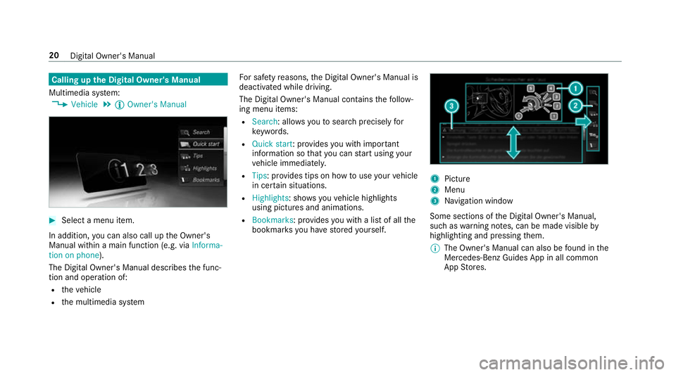
Calling up
the Digital Owner's Manual
Multimedia sy stem:
, Vehicle .
Õ Owner's Manual #
Select a menu item.
In addition, you can also call up the Owner's
Manual within a main function (e.g. via Informa-
tion on phone).
The Digital Owner's Manual describes the func‐
tion and operation of:
R theve hicle
R the multimedia sy stem Fo
r saf etyre asons, the Digital Owner's Manual is
deactivated while driving.
The Digital Owner's Manual conta insthefo llow‐
ing menu items:
R Search: allo wsyouto sear chprecisely for
ke ywords.
R Quick start: pr ovides you with impor tant
information so that you can start using your
ve hicle immediatel y.
R Tips: pr ovides tips on how touse your vehicle
in cer tain situations.
R Highlights : showsyouve hicle highlights
using pictures and animations.
R Bookmarks: pr ovides you with a list of all the
bookmar ksyou ha vestored yourself. 1
Picture
2 Menu
3 Navigation window
Some sections of the Digital Owner's Manual,
such as warning no tes, can be made visible by
highlighting and pressing them.
% The Owner's Manual can also be found in the
Mercedes-Benz Guides App in all common
App Stores. 20
Digital Owner's Manual
Page 31 of 557

These data memories
temp orarily or perma‐
nently store tech nical information abou t:
R theve hicle's operating state
R events
R faults
In general, thete ch nical information documents
th est ate of a component part, a module, a sys‐
te m or the sur roundings.
These include, forex ample:
R operating conditions of sy stem components,
e.g. fluid le vels
R theve hicle's status messages and those of
its individual components, e.g. number of
wheel revo lutions/speed, decele ration, lat‐
eral acceleration, accelerator pedal position
R malfunctions and de fects in impor tant sys‐
te m components, e.g. lights, brakes
R vehicle reactions and operating conditions in
special driving situations, e.g. airbag deploy‐
ment, inter vention of stability control sys‐
te ms
R ambient conditions, e.g. outside temp erature This data is of an
exclusively tech nical natu re
and can be used to:
R assist in de tecting and rectifying faults and
defects
R anal yseve hicle functions, e.g. af ter an acci‐
dent
R optimise vehicle functions
The data cannot be used totrace theve hicle's
mo vements.
When your vehicle is serviced, tech nical informa‐
tion can be read from theeve nt da tamemory
and fault data memor y.
Services include, forex ample:
R repair services
R service processes
R warranty events
The vehicle is read out byemplo yees of the
service network (including the manufacturer)
using special diagnostic devices. You can obtain
more information there, if requ ired. Af
ter a fault has been rectified, the information
is dele ted from thefa ult memory or is continu‐
ally overwritten.
When operating theve hicle, situations are con‐
ceivable in which this tech nical da ta, in connec‐
tion with other information (if necessar y,after
consultation wi than authorised expert), could be
traced toa person.
Examples include: R accident reports
R damage totheve hicle
R witness statements
Fu rther additional functions that ha vebeen con‐
tractually agreed upon with the cus tomer allow
cer tain vehicle data tobe con veye dby theve hi‐
cle as well. The additional functions include, for
ex ample, vehicle location in case of an emer‐
ge ncy. Co
pyright
Information on free and open source software
licences foryo ur vehicle's software can be found 28
General no tes
Page 34 of 557

Re
stra int sy stem functionality When
the ignition is switched on, a sy stem self-
te st is per form ed, during which the6
re stra int sy stem warning lamp lights up. It goes
out no later than a few seconds af terth eve hicle
is star ted. The components of there stra int sys‐
te m are then functional. Re
stra int sy stem malfunction R
The 6 restra int sy stem warning lamp
does not light up when the ignition is
switched on.
R The 6 restra int sy stem warning lamp
lights up continuously or repeatedly during a
journe y. &
WARNING Risk of inju ryor fata l injury
due toa malfunction in there stra int sys‐
tem
If th ere stra int sy stem is malfunctioning,
re stra int sy stem components may be trig‐
ge red unintentionally or might not be trig‐
ge red at all in theev ent of an accident. This may af
fect the seat belt tensioner or airbag,
fo rex ample. #
Have there stra int sy stem checked and
re paired immediately at a qualified spe‐
cialist workshop. Fu
nction of there stra int sy stem in an acci‐
dent How
there stra int sy stem works is de term ined by
th e se verity of the impact de tected and the type
of accident anticipated:
R Frontal impact
R Rear impact
R Side impact
R Rollover
The activation thre sholds forth e components of
th ere stra int sy stem are de term ined based on
th eev aluation of the sensor values measured at
va rious points in theve hicle. This process is pre-
em ptive in nature. The triggering/deployment of
th e components of there stra int sy stem should ta
ke place in good time at thest art of the colli‐
sion.
Fa ctors whi chcan only be seen and measu red
af te r a collision has occur red cann otplay a deci‐
sive role in airbag deployment, nor do they pro‐
vide an indication of airbag deployment.
The vehicle may be deformed significantly with‐
out an airbag being deplo yed. This is the case if
only parts which are relatively easily deformed
are af fected and thera te ofvehicle deceleration
is not high. Con versely, an airbag may be
deplo yedev en though theve hicle suf fers only
minor deformation. If very rigid vehicle parts
such as longitudinal members are hit, forex am‐
ple, this may result in suf ficiently high le vels of
ve hicle deceleration. Occupant saf
ety31