2016 MERCEDES-BENZ CLA COUPE radio
[x] Cancel search: radioPage 280 of 345
Mercedes-Benz emergency call sys-
tem
Information on these requirements can be found in the separate operating instructions. X
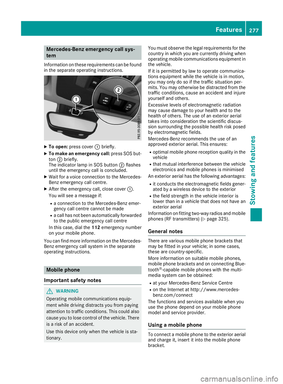
To open: press cover :briefly.
X To make an emergency call: press SOS but-
ton ;briefly.
The indicator lamp in SOS button ;flashes
until the emergency call is concluded.
X Wait for a voice connection to the Mercedes-
Benz emergency call centre.
X After the emergency call, close cover :.
You will see a message if:
R a connection to the Mercedes-Benz emer-
gency call centre cannot be made
R a call has not been automatically forwarded
to the public emergency call centre
In this case, dial the 112emergency number
on your mobile phone.
You can find more information on the Mercedes- Benz emergency call system in the separate
operating instructions. Mobile phone
Important safety notes G
WARNING
Operating mobile communications equip-
ment while driving distracts you from paying
attention to traffic conditions. This could also cause you to lose control of the vehicle. There
is a risk of an accident.
Use this device only when the vehicle is sta-
tionary. You must observe the legal requirements for the
country in which you are currently driving when
operating mobile communications equipment in the vehicle.
If it is permitted by law to operate communica-
tions equipment while the vehicle is in motion,
you may only do so if the traffic situation per-
mits. You may otherwise be distracted from the
traffic conditions, cause an accident and injure
yourself and others.
Excessive levels of electromagnetic radiation
may cause damage to your health and to the
health of others. The use of an exterior aerial
takes into consideration the scientific discus-
sion surrounding the possible health risk posed
by electromagnetic fields.
Mercedes-Benz recommends the use of an
approved exterior aerial. This ensures:
R optimal mobile phone reception quality in the
vehicle
R that mutual interference between the vehicle
electronics and mobile phones is minimised
An exterior aerial has the following advantages:
R it conducts the electromagnetic fields gener-
ated by a wireless device to the exterior
R the field strength in the vehicle interior is
lower than in a vehicle that does not have an
exterior aerial
Information on fitting two-way radios and mobile phones (RF transmitters) (Y page 325).
General notes There are various mobile phone brackets that
may be fitted in your vehicle; in some cases,
these are country-specific.
More information on suitable mobile phones,
mobile phone brackets and on connecting Blue-
tooth ®
-capable mobile phones with the multi-
media system can be obtained:
R at your Mercedes-Benz Service Centre
R on the Internet at http://www.mercedes-
benz.com/connect
The functions and services available when you
use the phone depend on your mobile phone
model and service provider.
Using a mobile phone To connect a mobile phone to the exterior aerial
and charge it, insert it into the mobile phone
bracket. Features
277Stowing and features Z
Page 282 of 345

X
Slide the seat backwards.
X To fit: lay the floormat in the footwell.
X Press safety catch knobs :onto retain-
ers ;.
X To remove: pull the floormat away from
retainers ;.
X Remove the floormats. Retrofitted anti-glare film
Retrofitted anti-glare film on the inside of the
windows can interfere with radio/mobile tele-
phone reception. This is particularly the case for conductive or metallic-coated films. You can
obtain information about anti-glare film from a
qualified specialist workshop. Features
279Stowing and features Z
Page 308 of 345
For towing distances over 50 km, the front
axle or the entire vehicle must be raised and
transported.
! To tow vehicles with KEYLESS-GO, use the
key instead of the Start/Stop button. The
automatic transmission may otherwise
switch to position Pwhen you open the driv-
er's or front-passenger door which could
damage the transmission.
! Vehicles with automatic transmission must
not be tow-started. The transmission may
otherwise be damaged.
Observe the legal requirements for the relevant
countries when towing and tow-starting.
It is better to have the vehicle transported than
to have it towed.
If the vehicle can no longer be driven because of an accident or breakdown, you have the follow- ing options:
R transporting the vehicle
As a rule, you should have the vehicle trans-
ported.
R towing the vehicle with a tow rope or tow bar
Only tow the vehicle in exceptional cases.
The battery must be connected and charged.
Otherwise, you:
R cannot turn the key to position 2in the igni-
tion lock
R cannot release the electric parking brake
R cannot shift the transmission to position Non
vehicles with automatic transmission
The function of the electric parking brake and
the parking lock is dependent on the on-board
voltage.
If the on-board voltage is low or if there is a sys-
tem malfunction:
R it may not be possible to apply the released
parking brake or
R it may not be possible to shift the transmis-
sion to position P
Switch off non-essential consumers, e.g. the
radio.
Deactivate the automatic locking feature before towing the vehicle (Y page 211). You could oth-
erwise be locked out when pushing or towing
the vehicle.
Deactivate tow-away protection before the vehi-
cle is towed away (Y page 74). Fitting/removing the towing eye
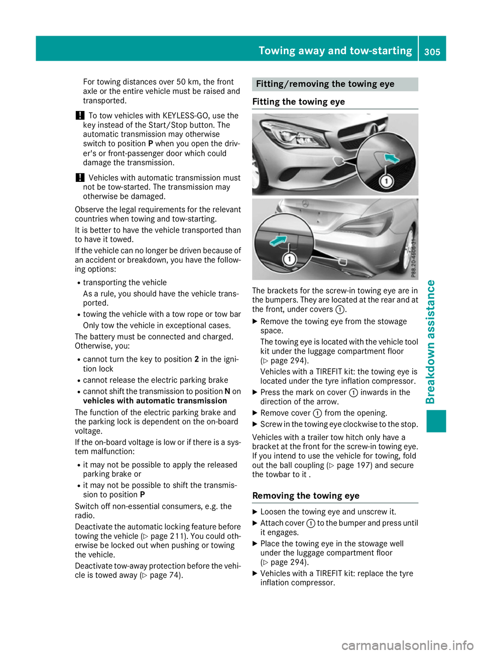
Fitting the towing eye The brackets for the screw-in towing eye are in
the bumpers. They are located at the rear and at
the front, under covers :.
X Remove the towing eye from the stowage
space.
The towing eye is located with the vehicle tool
kit under the luggage compartment floor
(Y page 294).
Vehicles with a TIREFIT kit: the towing eye is
located under the tyre inflation compressor.
X Press the mark on cover :inwards in the
direction of the arrow.
X Remove cover :from the opening.
X Screw in the towing eye clockwise to the stop.
Vehicles with a trailer tow hitch only have a
bracket at the front for the screw-in towing eye.
If you intend to use the vehicle for towing, fold
out the ball coupling (Y page 197) and secure
the towbar to it .
Removing the towing eye X
Loosen the towing eye and unscrew it.
X Attach cover :to the bumper and press until
it engages.
X Place the towing eye in the stowage well
under the luggage compartment floor
(Y page 294).
X Vehicles with a TIREFIT kit: replace the tyre
inflation compressor. Towing away and tow-starting
305Breakdown assistance Z
Page 319 of 345
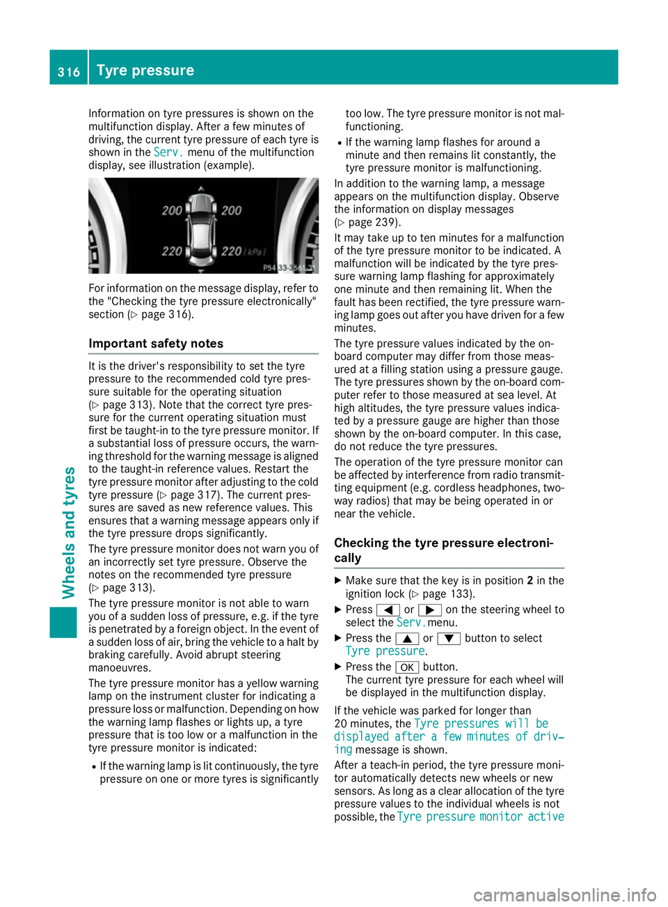
Information on tyre pressures is shown on the
multifunction display. After a few minutes of
driving, the current tyre pressure of each tyre is
shown in the Serv.
Serv. menu of the multifunction
display, see illustration (example). For information on the message display, refer to
the "Checking the tyre pressure electronically"
section (Y page 316).
Important safety notes It is the driver's responsibility to set the tyre
pressure to the recommended cold tyre pres-
sure suitable for the operating situation
(Y page 313). Note that the correct tyre pres-
sure for the current operating situation must
first be taught-in to the tyre pressure monitor. If
a substantial loss of pressure occurs, the warn- ing threshold for the warning message is aligned
to the taught-in reference values. Restart the
tyre pressure monitor after adjusting to the cold tyre pressure (Y page 317). The current pres-
sures are saved as new reference values. This
ensures that a warning message appears only if the tyre pressure drops significantly.
The tyre pressure monitor does not warn you of
an incorrectly set tyre pressure. Observe the
notes on the recommended tyre pressure
(Y page 313).
The tyre pressure monitor is not able to warn
you of a sudden loss of pressure, e.g. if the tyre is penetrated by a foreign object. In the event of
a sudden loss of air, bring the vehicle to a halt by
braking carefully. Avoid abrupt steering
manoeuvres.
The tyre pressure monitor has a yellow warning lamp on the instrument cluster for indicating a
pressure loss or malfunction. Depending on how
the warning lamp flashes or lights up, a tyre
pressure that is too low or a malfunction in the
tyre pressure monitor is indicated:
R If the warning lamp is lit continuously, the tyre
pressure on one or more tyres is significantly too low. The tyre pressure monitor is not mal-
functioning.
R If the warning lamp flashes for around a
minute and then remains lit constantly, the
tyre pressure monitor is malfunctioning.
In addition to the warning lamp, a message
appears on the multifunction display. Observe
the information on display messages
(Y page 239).
It may take up to ten minutes for a malfunction
of the tyre pressure monitor to be indicated. A
malfunction will be indicated by the tyre pres-
sure warning lamp flashing for approximately
one minute and then remaining lit. When the
fault has been rectified, the tyre pressure warn- ing lamp goes out after you have driven for a few
minutes.
The tyre pressure values indicated by the on-
board computer may differ from those meas-
ured at a filling station using a pressure gauge.
The tyre pressures shown by the on-board com- puter refer to those measured at sea level. At
high altitudes, the tyre pressure values indica-
ted by a pressure gauge are higher than those
shown by the on-board computer. In this case,
do not reduce the tyre pressures.
The operation of the tyre pressure monitor can
be affected by interference from radio transmit- ting equipment (e.g. cordless headphones, two-
way radios) that may be being operated in or
near the vehicle.
Checking the tyre pressure electroni-
cally X
Make sure that the key is in position 2in the
ignition lock (Y page 133).
X Press =or; on the steering wheel to
select the Serv. Serv.menu.
X Press the 9or: button to select
Tyre pressure
Tyre pressure.
X Press the abutton.
The current tyre pressure for each wheel will
be displayed in the multifunction display.
If the vehicle was parked for longer than
20 minutes, the Tyre pressures will be Tyre pressures will be
displayed
displayed after
aftera
afew
few minutes
minutes of
ofdriv‐
driv‐
ing
ing message is shown.
After a teach-in period, the tyre pressure moni-
tor automatically detects new wheels or new
sensors. As long as a clear allocation of the tyre
pressure values to the individual wheels is not
possible, the Tyre Tyrepressure
pressure monitor
monitoractive
active 316
Tyre pressureWheels and tyres
Page 320 of 345
message is shown instead of the tyre pressure
display. The tyre pressures are already being
monitored.
After an emergency spare wheel has been fitted,
the system may still display the tyre pressure of the removed wheel for a few minutes. If this
occurs, note that the value displayed for the
position where the spare wheel is fitted is not
the same as the current tyre pressure of the
emergency spare wheel.
Warning messages of the tyre pressure monitor If the tyre pressure monitor detects a pressure
loss in one or more tyres, a warning message is
shown in the multifunction display. The yellow
tyre pressure warning lamp then lights up:
R If the Please correct tyre pressure
Please correct tyre pressure
message appears in the multifunction display,
the tyre pressure in at least one tyre is too
low. The tyre pressure must be corrected
when the opportunity arises.
R If the Tyre Tyre pressure
pressure Check
Checktyre(s)
tyre(s) mes-
sage appears in the multifunction display, the tyre pressure in one or more tyres has drop-
ped significantly. The tyres must be checked.
R If the Tyre pressure Caution Tyre mal‐
Tyre pressure Caution Tyre mal‐
function
function message appears in the multifunc-
tion display, the tyre pressure in one or more tyres has dropped suddenly. The tyres must
be checked.
Observe the instructions and safety notes in the display messages in the "Tyres" section
(Y page 239).
If the position of the wheels on the vehicle is
changed, the tyre pressures may be displayed in the wrong positions for a short time. After a few
minutes of driving, this is rectified and the tyre
pressures are displayed in the correct positions.
Restarting the tyre pressure monitor When you restart the tyre pressure monitor, all
existing warning messages are deleted and the
warning lamps go out. The monitor uses the cur-
rently set tyre pressures as the reference values for monitoring. In most cases, the tyre pressure
monitor will automatically detect the new refer- ence values after you have changed the tyre
pressure. However, you can also set reference
values manually as described here. The tyre
pressure monitor then monitors the new tyre
pressure values. X
Use the table on the inside of the fuel filler flap
to ensure that the tyre pressure is set cor-
rectly in all four tyres for the current operating conditions.
Also observe the notes in the section on tyre
pressures (Y page 313).
X Make sure that the key is in position 2in the
ignition lock (Y page 133).
X Press =or; on the steering wheel to
select the Serv.
Serv.menu.
X Press the 9or: button to select
Tyre pressure Tyre pressure.
X Press the abutton.
The multifunction display shows the current
tyre pressure for each tyre or the Tyre Tyrepres‐
pres‐
sures
sures will
willbe
bedisplayed
displayed after
aftera
afew
few
minutes of driving
minutes of driving message.
X Press the :button.
The multifunction display shows the Use
Use
current pressures as new reference
current pressures as new reference
values values message.
If you wish to confirm the restart: X Press the abutton.
The Tyre
Tyre press.
press. monitor
monitor restarted
restarted mes-
sage appears in the multifunction display.
After you have driven for a few minutes, the
system checks whether the current tyre pres-
sures are within the specified range. The new tyre pressures are then accepted as refer-
ence values and monitored.
If you wish to cancel the restart:
X Press the %button.
The tyre pressure values stored at the last
restart will continue to be monitored.
Radio type approval for the tyre pres-
sure monitor Country Radio type approval number
Argentina MW2433A
H-12337
GG4
H-12338
Brazil 2770-12-8001
Model: MW2433A
0381-13-8001
Model: GG4 Tyre pressure
317Wheels and tyres Z
Page 321 of 345
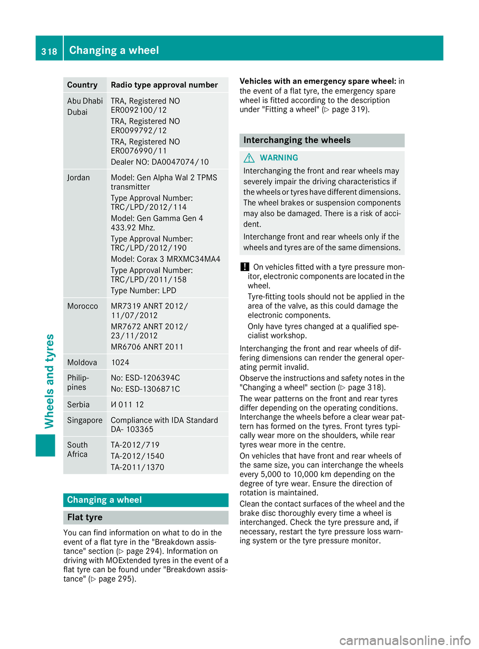
Country Radio type approval number
Abu Dhabi
Dubai TRA, Registered NO
ER0092100/12
TRA, Registered NO
ER0099792/12
TRA, Registered NO
ER0076990/11
Dealer NO: DA0047074/10
Jordan Model: Gen Alpha Wal 2 TPMS
transmitter
Type Approval Number:
TRC/LPD/2012/114
Model: Gen Gamma Gen 4
433.92 Mhz.
Type Approval Number:
TRC/LPD/2012/190
Model: Corax 3 MRXMC34MA4
Type Approval Number:
TRC/LPD/2011/158
Type Number: LPD Morocco MR7319 ANRT 2012/
11/07/2012
MR7672 ANRT 2012/
23/11/2012
MR6706 ANRT 2011
Moldova 1024
Philip-
pines No: ESD-1206394C
No: ESD-1306871C
Serbia И 011 12
Singapore Compliance with IDA Standard
DA- 103365
South
Africa TA-2012/719
TA-2012/1540
TA-2011/1370
Changing a wheel
Flat tyre
You can find information on what to do in the
event of a flat tyre in the "Breakdown assis-
tance" section (Y page 294). Information on
driving with MOExtended tyres in the event of a flat tyre can be found under "Breakdown assis-
tance" (Y page 295). Vehicles with an emergency spare wheel:
in
the event of a flat tyre, the emergency spare
wheel is fitted according to the description
under "Fitting a wheel" (Y page 319). Interchanging the wheels
G
WARNING
Interchanging the front and rear wheels may
severely impair the driving characteristics if
the wheels or tyres have different dimensions. The wheel brakes or suspension components may also be damaged. There is a risk of acci-
dent.
Interchange front and rear wheels only if the
wheels and tyres are of the same dimensions.
! On vehicles fitted with a tyre pressure mon-
itor, electronic components are located in the wheel.
Tyre-fitting tools should not be applied in thearea of the valve, as this could damage the
electronic components.
Only have tyres changed at a qualified spe-
cialist workshop.
Interchanging the front and rear wheels of dif-
fering dimensions can render the general oper-
ating permit invalid.
Observe the instructions and safety notes in the "Changing a wheel" section (Y page 318).
The wear patterns on the front and rear tyres
differ depending on the operating conditions.
Interchange the wheels before a clear wear pat-
tern has formed on the tyres. Front tyres typi-
cally wear more on the shoulders, while rear
tyres wear more in the centre.
On vehicles that have front and rear wheels of
the same size, you can interchange the wheels
every 5,000 to 10,000 km depending on the
degree of tyre wear. Ensure the direction of
rotation is maintained.
Clean the contact surfaces of the wheel and the
brake disc thoroughly every time a wheel is
interchanged. Check the tyre pressure and, if
necessary, restart the tyre pressure loss warn-
ing system or the tyre pressure monitor. 318
Changing a wheelWheels and tyres
Page 328 of 345
Information on technical data
i The technical data were determined in
accordance with EU Directives. All data apply
to the vehicle's standard equipment. The data may therefore differ for vehicles with optional
equipment. You can obtain further informa-
tion from a Mercedes-Benz Service Centre. Vehicle electronics
Tampering with the engine electron-
ics
! Only have work carried out on the engine
electronics and its associated parts, such as
control units, sensors, actuating components
and connector leads, at a qualified specialist
workshop. Vehicle components may other-
wise wear more quickly and the vehicle's
operating permit may be invalidated. Retrofitting two-way radios and
mobile phones (RF transmitters) G
WARNING
If RF transmitters are tampered with or not
properly retrofitted, the electromagnetic radi- ation they emit can interfere with the vehicle
electronics. This may jeopardise the opera-
tional safety of the vehicle. There is a risk of an
accident.
You should have all work on electrical and
electronic components carried out at a quali-
fied specialist workshop. G
WARNING
If you operate RF transmitters incorrectly in
the vehicle, the electromagnetic radiation
could interfere with the vehicle electronics,
e.g.:
R if the RF transmitter is not connected to an
exterior aerial
R the exterior aerial has been fitted incor-
rectly or is not a low-reflection type
This could jeopardise the operating safety of
the vehicle. There is a risk of an accident. Have the low-reflection exterior aerial fitted at
a qualified specialist workshop. When oper-
ating RF transmitters in the vehicle, always
connect them to the low-reflection exterior
aerial.
! The operating permit may be invalidated if
the instructions for installation and use of RF
transmitters are not observed.
In particular, the following conditions must be complied with:
R only approved wavebands may be used.
R observe the maximum permissible output
in these wavebands.
R only approved aerial positions may be
used.
Excessive levels of electromagnetic radiation
may cause damage to your health and to the
health of others. The use of an exterior aerial
takes into consideration the scientific discus-
sion surrounding the possible health risk posed
by electromagnetic fields.
Observe the notes on operating mobile phones
(Y page 277).
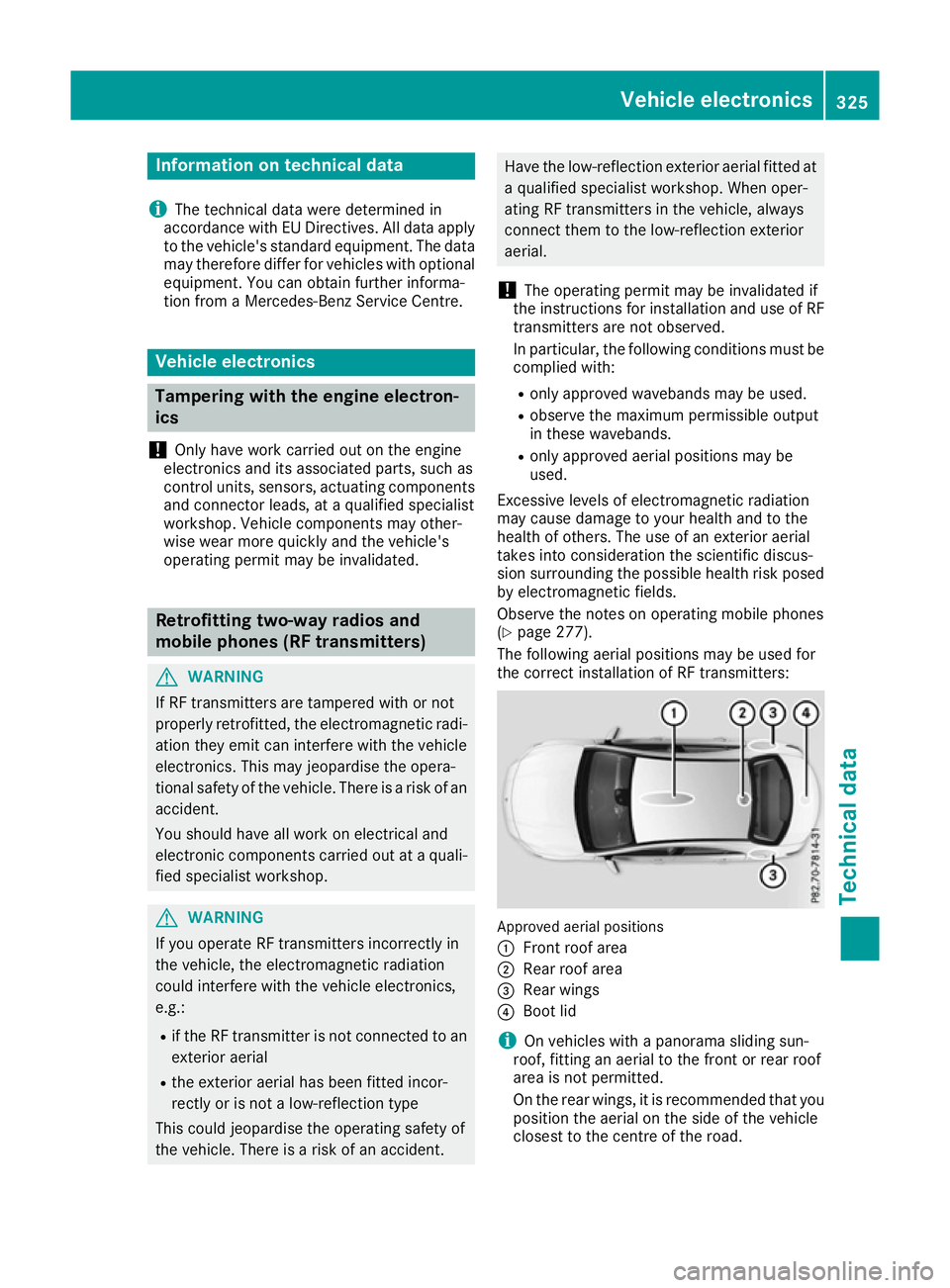
The following aerial positions may be used for
the correct installation of RF transmitters: Approved aerial positions
:
Front roof area
; Rear roof area
= Rear wings
? Boot lid
i On vehicles with a panorama sliding sun-
roof, fitting an aerial to the front or rear roof
area is not permitted.
On the rear wings, it is recommended that you
position the aerial on the side of the vehicle
closest to the centre of the road. Vehicle electronics
325Technical data Z
Page 329 of 345

Use Technical Specification ISO/TS 21609
(Road Vehicles – "EMC guidelines for installa-
tion of aftermarket radio frequency transmitting
equipment") when retrofitting RF transmitters.
Comply with the legal requirements for add-on
parts.
If your vehicle has fittings for two-way radio
equipment, use the power supply or aerial con-
nections intended for use with the basic fittings.
Be sure to observe the manufacturer's addi-
tional instructions when installing.
Deviations with respect to wavebands, maxi-
mum transmission outputs or aerial positions
must be approved by Mercedes-Benz.
The maximum transmission output (PEAK) at the base of the aerial must not exceed the followingvalues: Waveband Maximum
transmission output Short wave
3–54 MHz 100 W
4 m waveband
74–88 MHz 30 W
2 m waveband
144–174 MHz 50 W
Trunked radio/Tetra
380–460 MHz 10 W
70 cm waveband
400–460 MHz 35 W
Mobile communications
(2G/3G/4G) 10 W
The following can be used in the vehicle without
restrictions:
R RF transmitters with a maximum transmis-
sion output of up to 100 mW
R RF transmitters with transmitter frequencies
in the 380 - 410 MHz waveband and a maxi-
mum transmission output of up to 2 W
(trunked radio/Tetra)
R Mobile phones (2G/3G/4G) There are no restrictions when positioning the
aerial on the outside of the vehicle for the fol-
lowing wavebands:
R Trunked radio/Tetra
R 70 cm waveband
R 2G/3G/4G Identification plates
Vehicle identification plate with vehi-
cle identification number (VIN)
X
Open the front right-hand door.
You will see the vehicle identification
plate :. Vehicle identification plate (example: vehicles with
a trailer tow hitch)
: Vehicle manufacturer (Daimler AG)
; EU type approval number (for certain coun-
tries only)
= VIN
? Maximum gross vehicle weight (kg)
A Maximum gross vehicle weight of vehicle
combination (kg) (for specific countries
only)
B Permissible front axle load (kg) 326
Identification platesTechnical data