2016 MERCEDES-BENZ CLA COUPE lock
[x] Cancel search: lockPage 24 of 345
Trim pieces (cleaning instruc-
tions)
.................................................. 291
Trip computer (on-board com-
puter) .................................................. 203
Trip meter
Calling up ....................................... 203
Resetting (on-board computer) ...... 204
Turn signal lamp
Replacing bulbs (rear ).................... 113
Turn signals
Replacing bulbs (front) ................... 113
Switching on/of f........................... 109
Two-way radio
Frequencies ................................... 325
Installation ..................................... 325
Transmission output (maximum) .... 325
Type identification plate
see Vehicle identification plate
Tyre inflation compressor
see TIREFIT kit
Tyre pressure
Calling up (on-board computer) ..... 315
Display message ............................ 239
Not reached (TIREFIT) .................... 297
Reached (TIREFIT) .......................... 298
Recommended ............................... 313
Tyre pressure loss warning
General notes ................................ 314
Important safety notes .................. 315
Restarting ...................................... 315
Tyre pressure monitor
Checking the tyre pressure elec-
tronically ........................................ 316
Function/note s............................. 315
General notes ................................ 315
Important safety notes .................. 316
Radio type approval for the tyre
pressure monitor ........................... 317
Restarting ...................................... 317
Warning lamp ................................. 258
Warning message .......................... 317
Tyres
Changing a whee l.......................... 318
Checking ........................................ 310
Direction of rotation ...................... 319
Display message ............................ 239
General notes ................................ 323
Important safety notes .................. 310 Information on driving .................... 310
M+S tyres ...................................... 312
MOExtended tyre
s......................... 312
Replacing ....................................... 318
Service life ..................................... 311
Storing ........................................... 319
Summer tyres ................................ 312
Tyre size (data ).............................. 323
Tyre tread ...................................... 311
see Flat tyre U
Unlocking Emergency unlocking ....................... 85
From inside the vehicle (central
unlocking button) ............................. 84
Upshift indicator (on-board com-
puter, Mercedes-AMG vehicles) ....... 213
USB devices
Connecting to the Media Inter-
face ............................................... 267 V
Vanity mirror (in sun visor) .............. 275
Vehicle
Correct use ...................................... 28
Data acquisition ............................... 28
Display message ............................ 241
Electronics ..................................... 325
Equipment ....................................... 25
Implied warranty .............................. 28
Individual settings .......................... 210
Leaving parked up ......................... 159
Locking (in an emergency) ............... 85
Locking (key) ................................... 76
Lowering ........................................ 322
Pulling away ................................... 135
Raising ........................................... 320
Registration ..................................... 28
Securing from rolling away ............ 319
Transporting .................................. 307
Unlocking (in an emergency) ........... 85
Unlocking (key) ................................ 76
Vehicle data ................................... 333
Vehicle data
Boot load (maximum) ..................... 333
Roof load (maximum) ..................... 333 Index
21
Page 25 of 345
Vehicle dimensions
........................... 333
Vehicle emergency locking ................ 85
Vehicle identification number
see VIN
Vehicle identification plate .............. 326
Vehicle tool kit .................................. 294
Ventilation
Setting the vents ........................... 130
Video
Operating the DVD ......................... 206
See also Digital Owner's Manua l... 259
VIN
Seat ............................................... 327
Type plate ...................................... 326 W
Warning and indicator lamps ABS ................................................ 250
Active Brake Assist ........................ 257
Brakes ........................................... 249
Distance warning signal ................. 257
ESP ®
.............................................. 252
ESP ®
OFF ....................................... 253
Fuel tank ........................................ 255
LIM (cruise control) ........................ 163
LIM (Distance Pilot DISTRONIC) .... 168
LIM (variable limiter) ...................... 165
Overview .......................................... 32
PASSENGER AIR BAG ...................... 40
Reserve fue l................................... 255
Seat belt ........................................ 248
Tyre pressure monitor ................... 258
Warning triangle ................................ 293
Washer fluid
Display message ............................ 246
Weather display (COMAND Online)
See also Digital Owner's Manua l... 259
Wheel and tyre combinations
Tyres .............................................. 323
Wheel bolt tightening torque ........... 322
Wheel chock ...................................... 319
Wheels
Changing a whee l.......................... 318
Changing/replacing ....................... 318
Checking ........................................ 310
Cleaning ......................................... 288
Emergency spare whee l................. 323 Fitting a new wheel ........................ 321
Important safety notes .................. 310
Information on driving .................... 310
Removing a whee
l.......................... 321
Storing ........................................... 319
Tightening torque ........................... 322
Wheel size/tyre size ...................... 323
Windowbag
Display message ............................ 225
Operation ......................................... 46
Windows
Cleaning ......................................... 288
see Side windows
Windscreen
Demisting ...................................... 123
Windscreen washer system
Important safety notes .................. 332
Topping up ..................................... 284
Windscreen wipers
Display message ............................ 246
Problem (malfunction) ................... 116
Replacing the wiper blades ............ 115
Switching on/of f........................... 114
Winter driving
General notes ................................ 312
Winter operation
Slippery road surfaces ................... 162
Snow chains .................................. 313
Winter tyres
Limiting the speed (on-board com-
puter) ............................................. 211
M+S tyre s...................................... 312
Wiper blades
Cleaning ......................................... 288
Important safety notes .................. 115
Wooden trim (cleaning instruc-
tions) .................................................. 291
Workshop
see Qualified specialist workshop Z
ZONE function Switching on/of f........................... 123 22
Index
Page 30 of 345
4. Hradec nad Moravicí
City
5. 05.05.2015 Date
Signed by:
Director of Quality
TIREFIT kit Copy and translation of the original declaration of conformity:
EC declaration of conformity
In accordance with EC directive 2006/42/EC
We hereby declare that the product
Product designation: Daimler electric air pump
Model designation: 0852, DT/UW 200016
MB part no.: A 000 583 22 02
complies with the following relevant regulations:
EMC 72/245/EC
Applied harmonised standards, in particular:
ISO 7637-2: 2004
Manufacturer: Dunlop Tech GmbH
Address: Birkenhainerstrasse 77, 63450
Hanau, Germany
Authorised representative :I MS department
Date: June 2011
Signature: IMS-AM, IMS-AE-LDiagnostics connection
The diagnostics connection is used for connect- ing diagnostic equipment at a qualified special-
ist workshop. G
WARNING
If you connect equipment to a diagnostics
connection in the vehicle, it may affect the
operation of vehicle systems. As a result, the operating safety of the vehicle could be affec-
ted. There is a risk of an accident.
Only connect equipment to a diagnostics con-
nection in the vehicle, which is approved for
your vehicle by Mercedes-Benz. G
WARNING
Objects in the driver's footwell may restrict
the clearance around the pedals or block a
depressed pedal. This jeopardises the oper-
ating and road safety of the vehicle. There is a risk of an accident. Stow all objects securely in the vehicle so that
they do not get into the driver's footwell.
Always fit the floormats securely and as pre-
scribed in order to ensure that there is always sufficient room for the pedals. Do not use
loose floormats and do not place several floor-
mats on top of one another.
! If the engine is switched off and equipment
on the diagnostics connection is used, the
starter battery may discharge.
Connecting equipment to the diagnostics con-
nection can lead to emissions monitoring infor-
mation being reset, for example. This may lead
to the vehicle failing to meet the requirements of the next emissions test during the main inspec-
tion. Qualified specialist workshop
A qualified specialist workshop has the neces-
sary special skills, tools and qualifications to
correctly carry out any necessary work on your Operating safety
27Introduction Z
Page 33 of 345
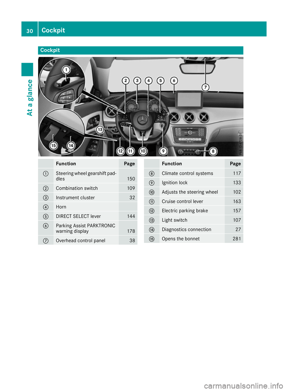
Cockpit
Function Page
:
Steering wheel gearshift pad-
dles 150
;
Combination switch 109
=
Instrument cluster 32
?
Horn
A
DIRECT SELECT lever 144
B
Parking Assist PARKTRONIC
warning display
178
C
Overhead control panel 38 Function Page
D
Climate control systems 117
E
Ignition lock 133
F
Adjusts the steering wheel 102
G
Cruise control lever 163
H
Electric parking brake 157
I
Light switch 107
J
Diagnostics connection 27
K
Opens the bonnet 28130
CockpitAt a glance
Page 34 of 345
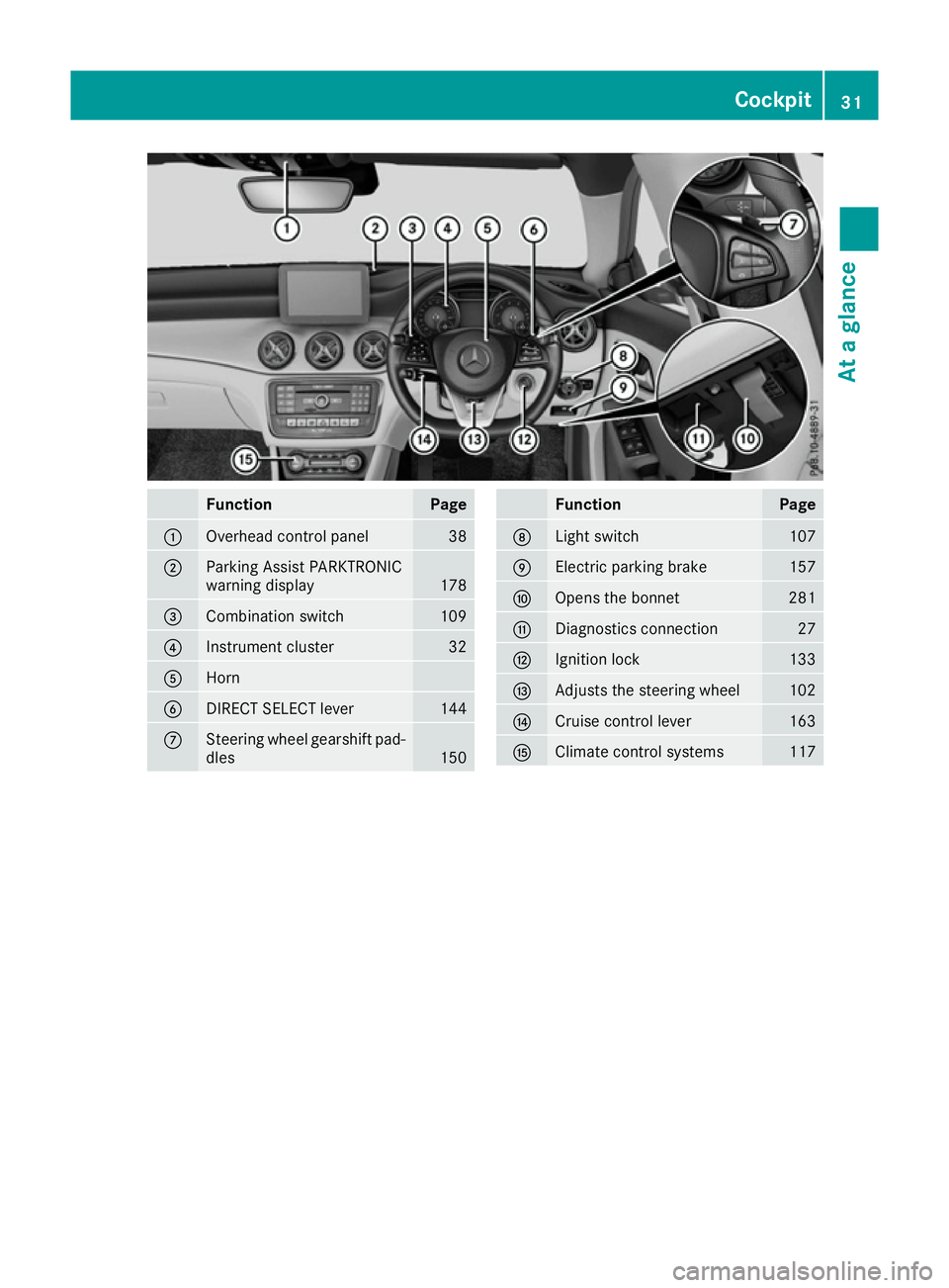
Function Page
:
Overhead control panel 38
;
Parking Assist PARKTRONIC
warning display
178
=
Combination switch 109
?
Instrument cluster 32
A
Horn
B
DIRECT SELECT lever 144
C
Steering wheel gearshift pad-
dles 150 Function Page
D
Light switch 107
E
Electric parking brake 157
F
Opens the bonnet 281
G
Diagnostics connection 27
H
Ignition lock 133
I
Adjusts the steering wheel 102
J
Cruise control lever 163
K
Climate control systems 117Cockpit
31At a glance
Page 40 of 345
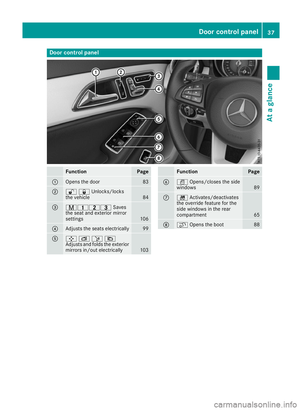
Door control panel
Function Page
:
Opens the door 83
;
%&Unlocks/locks
the vehicle
84
=
r45=
Saves
the seat and exterior mirror
settings 106
?
Adjusts the seats electrically 99
A
7
Zö\
Adjusts and folds the exterior
mirrors in/out electrically 103 Function Page
B
W
Opens/closes the side
windows 89
C
n
Activates/deactivates
the override feature for the
side windows in the rear
compartment 65
D
q
Opens the boot 88Door control panel
37At a glance
Page 42 of 345

Panic alarm
X
To activate: press and hold
! button :for approx. one second.
A visual and audible alarm is triggered if the
alarm system is primed.
X To deactivate: press!button :again.
or
X Insert the key into the ignition lock.
or, on vehicles with KEYLESS-GO start function
or KEYLESS ‑GO:
X Press the Start/Stop button.
The key must be in the vehicle.
The panic alarm function is only available in cer-
tain countries. Occupant safety
Introduction to the restraint system
The restraint system can reduce the risk of vehi-
cle occupants coming into contact with parts of
the vehicle's interior in the event of an accident. Furthermore, the restraint system can also
reduce the forces to which vehicle occupants
are subjected during an accident.
The restraint system includes:
R Seat belt system
R Airbags
R Child restraint system
R Child seat securing system The various components of the restraint system
work complementary to one another. They can
only perform their intended protective function
if all vehicle occupants:
R have correctly fastened their seat belt
(Y page 42)
R have correctly adjusted their seat and head
restraint (Y page 97).
As the driver, you must also ensure that the
steering wheel is correctly adjusted. Observe
the information relating to the correct driver's
seat position (Y page 97).
Additionally, you must ensure that an airbag can
deploy freely (Y page 44).
The airbag is supplementary to a correctly fas-
tened seat belt. As an additional safety device,
the airbag increases the level of protection for
vehicle occupants in the event of an accident. If
the protection provided by the seat belt is suf-
ficient, the airbags do not deploy. Furthermore, in the event of an accident, only airbags which
provide greater protection in the given accident
situation deploy. However, seat belts and air-
bags generally do not protect against objects
penetrating the vehicle from the outside.
Information on how the restraint system oper-
ates can be found in "Deployment of the seat
belt tensioner and airbags" (Y page 51).
See "Children in the vehicle" for information on
infants and children traveling with you in the
vehicle restraint systems for infants and chil-
dren(Y page 54). Important safety notes
G
WARNING
If the restraint system is modified, it may no
longer work as intended. The restraint system
may then not perform its intended protective function by failing in an accident or triggering
unexpectedly, for example. There is an
increased risk of injury, possibly even fatal.
Never modify parts of the restraint system. Do not attempt to modify the wiring as well as
electronic components or their software.
If the vehicle needs to be adapted to accommo- date a person with disabilities, please contact a
specialist workshop. Occupant safety
39Safety Z
Page 44 of 345
tion system" (Y
page 47) and on "Children in
the vehicle" (Y page 54).
R All other persons: the PASSENGER AIR BAG
OFF indicator lamp must be off. The front-
passenger front airbag is enabled. Depending
on the stature of the person on the front-
passenger seat, the PASSENGER AIR BAG
OFF indicator lamp may light up. The front-
passenger front airbag is disabled. It will then
not be deployed in the event of an accident. In this case, the front-passenger seat should not
be used.
It is imperative to observe the notes on the
"Automatic front-passenger front airbag
deactivation system" (Y page 47) as well as
on "Seat belts" (Y page 41) and "Airbags"
(Y page 44). There, you can also find infor-
mation on the correct seat position. Seat belts
Introduction A correctly worn seat belt is the most effective
means of restraining the movement of vehicle
occupants in the event of a collision or if the
vehicle overturns. This reduces the risk of vehi-
cle occupants coming into contact with parts of
the vehicle interior or being ejected from it. The seat belt also helps to keep the vehicle occu-
pants in the best position in relation to the air-
bag being deployed.
The seat belt system consists of:
R seat belts
R belt tensioners for the front seat belts and the
outer seat belts in the rear
R belt force limiters for the front seat belts and
the outer seat belts in the rear
If the seat belt is pulled quickly or sharply from
the belt outlet, the inertia reel locks. The belt
strap cannot be pulled out any further.
The belt tensioner tightens the seat belt in the
event of a collision so that it fits tightly across
your body. However, it does not pull the vehicle
occupants back in the direction of the seat
backrest.
The belt tensioner does not, however, correct an
incorrect seat position or correct the routing of a seat belt that is worn incorrectly.
When triggered, seat belt force limiters help to
reduce the peak force exerted by the seat belt
on the vehicle occupant. The belt force limiters on the front seats are
synchronised with the front airbags, which take
on a part of the deceleration force. This can
reduce the forces to which the vehicle occu-
pants are subjected during an accident.
! If the co-driver's seat is not occupied, do not
engage the seat belt tongue in the buckle on
the co-driver's seat. Otherwise, the belt ten-
sioner could be triggered in the event of an
accident and would have to be replaced.
Important safety notes G
WARNING
If the seat belt is worn incorrectly, it cannot
perform its intended protective function. Fur- thermore, an incorrectly worn seat belt can
cause additional injuries, e.g. in the event of
an accident, heavy braking or sudden
changes of direction. There is an increased
risk of injury, possibly even fatal.
Always ensure that all vehicle occupants havetheir seat belts fastened correctly and are sit-
ting properly. G
WARNING
The seat belt does not offer the intended level of protection if you have not moved the back-
rest to an almost vertical position. When brak-
ing or in the event of an accident, you could
slide underneath the seat belt and sustain
abdomen or neck injuries, for example. This
poses an increased risk of injury or even fatal injury.
Adjust the seat properly before beginning
your journey. Always ensure that the backrest
is in an almost vertical position and that the
shoulder section of your seatbelt is routed
across the centre of your shoulder. G
WARNING
Persons under 1.50 mtall cannot wear the
seat belts correctly without an additional suit- able restraint system. If the seat belt is worn
incorrectly, it cannot perform its intended
protective function. Furthermore, an incor-
rectly worn seat belt can cause additional
injuries, e.g. in the event of an accident, heavy Occupant safety
41Safety
Z