2016 MERCEDES-BENZ AMG GT ROADSTER flat tire
[x] Cancel search: flat tirePage 13 of 289
Checking the oil level using the
dipstick .......................................... 233
Checking the oil level using the
on-board computer ........................ 234
Display message ............................ 184
Filling capacity .............................. .279
Notes about oil grades ................... 279
Notes on oil level/consumption .... 233
Temperature (on-board com-
puter) ............................................. 167
Topping up ..................................... 234
Entering an address
See also Digital Owner's Manual ... 205
Environmental protection
Returning an end-of-life vehicle ....... 22
ESP ®
(Electronic Stability Pro-
gram)
AMG menu (on-board computer) ... 168
Characteristics ................................. 58
Deactivating/activating ................... 58
Display message ............................ 172
Function/notes ................................ 57
General notes .................................. 57
Important safety guidelines ............. 58
Warning lamp ................................. 197
ETS/4ETS (Electronic Traction Sys-
tem) ...................................................... 58
Exhaust pipe (cleaning instruc-
tions) ................................................. .242
Exterior lighting
Cleaning ......................................... 241
see Lights
Exterior mirrors
Adjusting ......................................... 84
Anti-dazzle mode (automatic) .......... 85
Folding in/out (automatically) ......... 85
Folding in/out (electrically) ............. 85
Out of position (troubleshooting) ..... 85
Parking position ............................... 86
Resetting ......................................... 85
Storing settings (memory func-
tion) ................................................. 87 F
Fault message see Display messages Favourites
Overview ........................................ 208
Features ............................................. 220
Filler cap
see Fuel filler flap
Fire extinguisher ............................... 245
First-aid kit ......................................... 245
Fitting a wheel
Fitting a wheel ............................... 271
Lowering the vehicle ...................... 272
Preparing the vehicle ..................... 268
Raising the vehicle ......................... 269
Removing a whee l.......................... 270
Securing the vehicle against roll-
ing away ........................................ 268
Flat tyre
Changing a wheel/fitting the
spare whee l................................... 267
Preparing the vehicle ..................... 247
TIREFIT kit ...................................... 247
see Emergency spare wheel
Floormat ............................................. 230
Frequencies
Garage door opener ....................... 228
Mobile phone ................................. 275
Two-way radio ................................ 275
Front-passenger front airbag deac-
tivation system
Operation ......................................... 42
Problems ......................................... 45
System self-test ............................... 44
Fuel
Additives ........................................ 279
Consumption statistics .................. 158
Displaying the current consump-
tion ................................................ 158
Displaying the range ...................... 158
Driving tip s.................................... 123
E10 ................................................ 278
Fuel gauge ....................................... 29
Grade (petrol) ................................ 278
Important safety notes .................. 277
Problem (malfunction) ................... 119
Refuelling ....................................... 117
Tank content/reserve fue l............. 278
Fuel filler flap
Closing ........................................... 118
General information ....................... 118 10
Index
Page 22 of 289
Trim pieces (cleaning instruc-
tions)
.................................................. 243
Trip computer (on-board com-
puter) .................................................. 158
Trip meter
Calling up ....................................... 157
Resetting (on-board computer) ...... 158
Turn signals
Switching on/off .............................. 89
Two-way radio
Frequencies ................................... 275
Installation ..................................... 275
Transmission output (maximum) .... 275
Type identification plate
see Vehicle identification plate
Tyre changing tool kit ....................... 246
Tyre inflation compressor
see TIREFIT kit
Tyre pressure
Calling up (on-board computer) ..... 265
Display message ............................ 189
Not reached (TIREFIT) .................... 249
Reached (TIREFIT) .......................... 249
Recommended ............................... 264
Tyre pressure monitor
Checking the tyre pressure elec-
tronically ........................................ 266
Function/note s............................. 265
General notes ................................ 265
Important safety notes .................. 266
Restarting ...................................... 267
Warning lamp ................................. 203
Warning message .......................... 267
Tyres
Changing a whee l.......................... 267
Checking ........................................ 262
Direction of rotation ...................... 268
Display message ............................ 189
Important safety notes .................. 261
Information on driving .................... 261
Replacing ....................................... 267
Service life ..................................... 262
Storing ........................................... 268
Summer tyres in winter ................. 263
Tyre size (data ).............................. 272
Tyre tread ...................................... 262
Wheel and tyre combinations ........ 272
see Flat tyre U
Unlocking Emergency unlocking ....................... 70
From inside the vehicle (central
unlocking button) ............................. 70
USB devices
Connecting to the Media Inter-
face ............................................... 216 V
Vanity mirror (in sun visor) .............. 221
Vehicle
Correct use ...................................... 25
Data acquisition ............................... 26
Display message ............................ 190
Electronics ..................................... 275
Equipment ....................................... 23
Implied warranty .............................. 25
Individual settings .......................... 164
Leaving parked up ......................... 122
Locking (in an emergency) ............... 70
Locking (key) ................................... 64
Lowering ........................................ 272
Operating safety .............................. 23
Parking .......................................... 119
Pulling away ................................... 104
Raising ........................................... 269
Registration ..................................... 25
Securing from rolling away ............ 268
Towing away .................................. 256
Transporting .................................. 258
Unlocking (in an emergency) ........... 70
Unlocking (key) ................................ 64
Vehicle data ................................... 281
Vehicle data
Boot load (maximum) ..................... 281
Vehicle dimensions ........................... 281
Vehicle emergency locking ................ 70
Vehicle identification number
see VIN
Vehicle identification plate .............. 276
Vehicle tool kit .................................. 246
Video
Operating the DVD ......................... 162
See also Digital Owner's Manua l... 205 Index
19
Page 44 of 289
When deployed, the sidebag offers additional
thorax protection. However, it does not protect
the:
R head
R neck
R arms
AMG Performance seat: increased pelvis pro-
tection is also offered for occupants in the front seats.
In the event of a side impact, the sidebag is
deployed on the side on which the impact
occurs.
The sidebag on the front-passenger side deploys
under the following conditions:
R the automatic front-passenger front airbag
deactivation system has detected that the
front-passenger seat is occupied, or
R the seat belt buckle tongue is engaged in the
belt buckle of the front-passenger seat
If the belt tongue is engaged in the belt buckle,
the sidebag on the front-passenger side deploys if an appropriate accident situation occurs. In
this case, deployment is independent of
whether the front-passenger seat is occupied or
not.
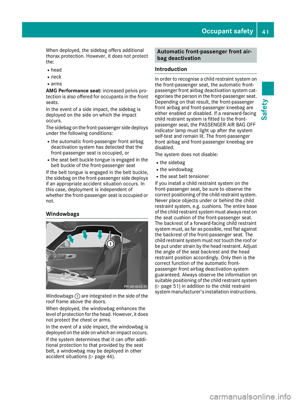
Windowbags Windowbags
:are integrated in the side of the
roof frame above the doors.
When deployed, the windowbag enhances the
level of protection for the head. However, it does
not protect the chest or arms.
In the event of a side impact, the windowbag is
deployed on the side on which an impact occurs.
If the system determines that it can offer addi-
tional protection to that provided by the seat
belt, a windowbag may be deployed in other
accident situations (Y page 46). Automatic front-passenger front air-
bag deactivation
Introduction In order to recognise a child restraint system on
the front-passenger seat, the automatic front-
passenger front airbag deactivation system cat- egorises the person in the front-passenger seat.Depending on that result, the front-passenger
front airbag and front-passenger kneebag are
either enabled or disabled. If a rearward-facing
child restraint system is fitted to the front-
passenger seat, the PASSENGER AIR BAG OFF
indicator lamp must light up after the system
self-test and remain lit. The front-passenger
front airbag and front-passenger kneebag are
disabled.
The system does not disable:
R the sidebag
R the windowbag
R the seat belt tensioner
If you install a child restraint system on the
front-passenger seat, be sure to observe the
correct positioning of the child restraint system. Never place objects under or behind the child
restraint system, e.g. cushions. The entire baseof the child restraint system must always rest on
the seat cushion of the front-passenger seat.
The backrest of a forward-facing child restraint
system must, as far as possible, rest flat against the backrest of the front-passenger seat. The
child restraint system must not touch the roof or
be put under strain by the head restraint. Adjust the angle of the seat backrest and the head
restraint position accordingly. Only then is the
correct function of the automatic front-
passenger front airbag deactivation system
guaranteed. Always observe the information onsuitable positioning of the child restraint system
(Y page 51) in addition to the child restraint
system manufacturer's installation instructions. Occupant safety
41Safety Z
Page 54 of 289
If the PASSENGER AIR BAG OFF indicator lamp
goes out, the front-passenger front airbag is
enabled (Y page 35).
Vehicles without the automatic front-
passenger front airbag deactivation
system If the front-passenger seat of your vehicle is not
equipped with the automatic front-passenger
front airbag deactivation system, this is indica-
ted by a special sticker. The sticker is affixed to
the side of the dashboard on the front-
passenger side. The sticker is visible when you
open the front-passenger door.
In this case, never fit a rearward-facing child
restraint system on the front passenger seat
(Y page 51).
Observe the following information under "Rear-
ward-facing child restraint system"
(Y page 51) and "Forward-facing child
restraint system" (Y page 51) as well as infor-
mation on the suitable positioning of the child
restraint system (Y page 51).
Rearward-facing child restraint system If you secure a child in a rearward-facing child
restraint system on the front-passenger seat,
always make sure that the front-passenger front airbag is disabled. Only if the PASSENGER AIR
BAG OFF indicator lamp is lit continuously
(Y page 35) is the front-passenger front airbag
disabled.
Always observe the information on suitable
positioning of the child restraint system
(Y page 51) in addition to the child restraint
system manufacturer's installation and operat-
ing instructions. Forward-facing child restraint system If you secure a child in a forward-facing child
restraint system on the front-passenger seat,
always move the front-passenger seat as far
back as possible. The entire base of the child
restraint system must always rest on the seat
cushion of the front-passenger seat. The back-
rest of the child restraint system must, as far as
possible, lie flat against the backrest of the
front-passenger seat. The child restraint system must not touch the roof or be put under strain bythe head restraint. Adjust the angle of the seat
backrest and the head restraint position accord-
ingly. Always make sure that the shoulder belt
strap is correctly routed from the front-
passenger seat belt loop to the shoulder belt
guide on the child restraint system. The shoul-
der belt strap must be routed forwards and
downwards from the front-passenger seat belt
loop.
Always observe the information on suitable
positioning of the child restraint system
(Y page 51) in addition to the child restraint
system manufacturer's installation and operat-
ing instructions. Suitable positioning of the child
restraint system
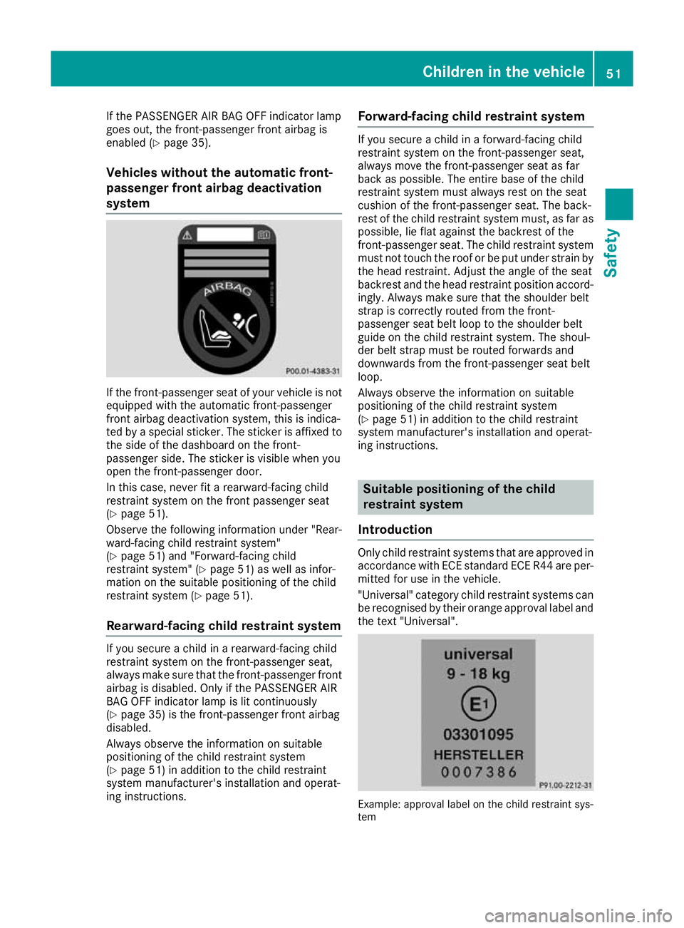
Introduction Only child restraint systems that are approved in
accordance with ECE standard ECE R44 are per-
mitted for use in the vehicle.
"Universal" category child restraint systems can
be recognised by their orange approval label and the text "Universal". Example: approval label on the child restraint sys-
tem Children in the vehicle
51Safety Z
Page 55 of 289
"Universal" category child restraint systems can
be used on seats indicated with U or UF in
accordance with the "Suitability of the front-
passenger seat for attaching belt-secured child
restraint systems" table.
Semi-universal child restraint systems are indi-
cated by the text "semi-universal" on the
approval label. These can be used if the vehicle and the seat are listed in the child restraint sys-
tem manufacturer's vehicle model list. For more
information, contact the child restraint system
manufacturer or visit their website.
If you install a child restraint system on the
front-passenger seat:
X Always pay attention to the instructions under
"Child restraint system on the front-
passenger seat" (Y page 50).
There you will find instructions on how to cor-
rectly route the shoulder belt strap from the front-passenger seat belt guide to the shoul-
der belt guide on the child restraint system
(Y page 51).
X Move the front-passenger seat as far back as
possible and into the highest position.
X Move the backrest to an almost vertical posi-
tion.
The entire base of the child restraint system
must always rest on the seat cushion of the
front-passenger seat. The backrest of a
forward-facing child restraint system must, asfar as possible, rest flat against the backrest
of the front-passenger seat. The child
restraint system must not touch the roof.
Adjust the backrest angle accordingly. Also
observe the child restraint system manufac-
turer's installation instructions.
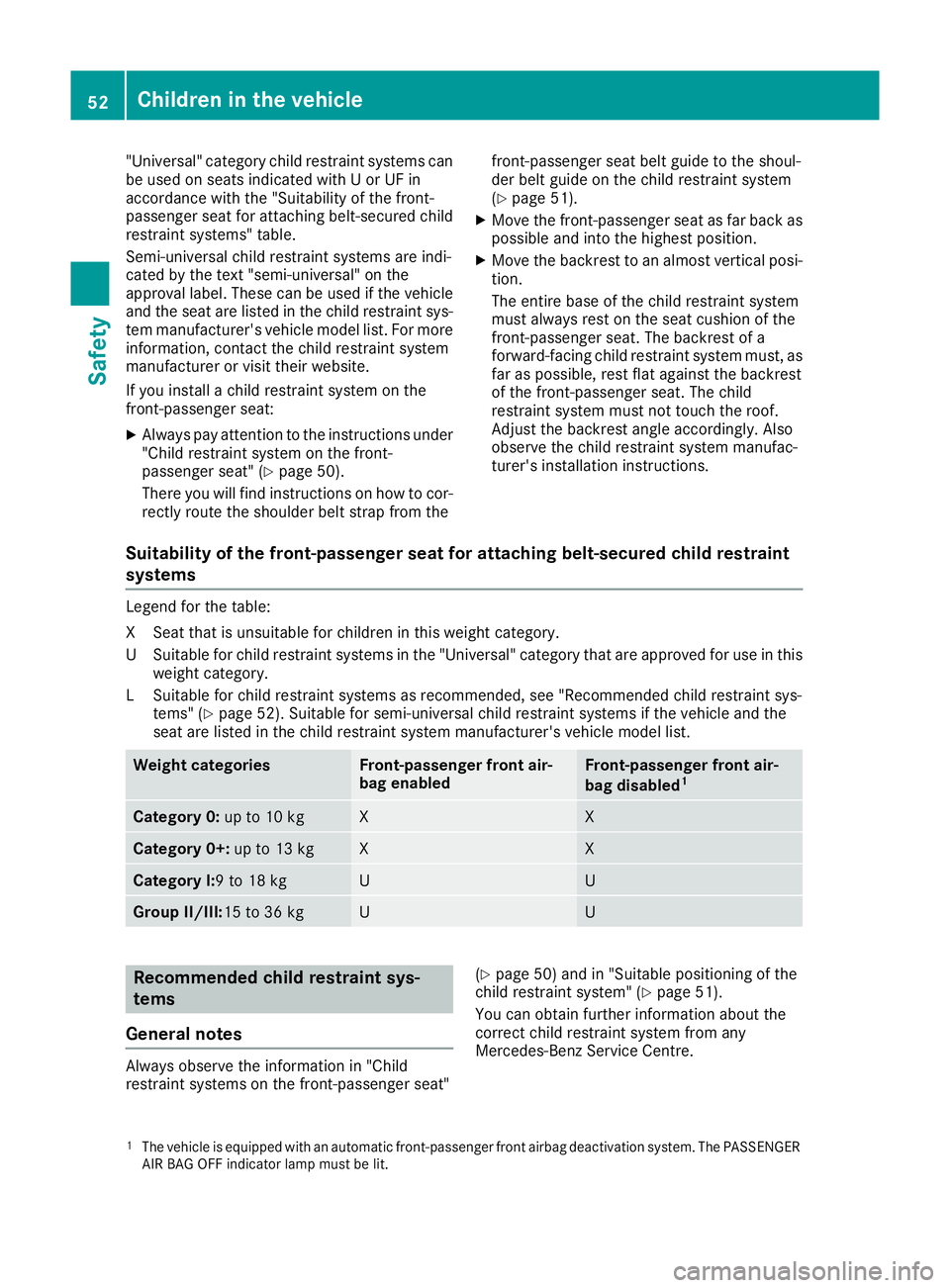
Suitability of the front-passenger seat for attaching belt-secured child restraint
systems Legend for the table:
XS
eat that is unsuitable for children in this weight category.
US uitable for child restraint systems in the "Universal" category that are approved for use in this
weight category.
LS uitable for child restraint systems as recommended, see "Recommended child restraint sys-
tems" (Y page 52). Suitable for semi-universal child restraint systems if the vehicle and the
seat are listed in the child restraint system manufacturer's vehicle model list. Weight categories Front-passenger front air-
bag enabled Front-passenger front air-
bag disabled
1 Category 0:
up to 10 kg X X
Category 0+:
up to 13 kg X X
Category I:9 to 18 kg U U
Group II/III:
15 to 36 kg U U
Recommended child restraint sys-
tems
General notes Always observe the information in "Child
restraint systems on the front-passenger seat" (Y
page 50) and in "Suitable positioning of the
child restraint system" (Y page 51).
You can obtain further information about the
correct child restraint system from any
Mercedes-Benz Service Centre.
1 The vehicle is equipped with an automatic front-passenger front airbag deactivation system. The PASSENGER
AIR BAG OFF indicator lamp must be lit. 52
Children in the vehicleSafety
Page 249 of 289
Vehicle tool kit
General notes Apart from some country-specific variants, vehi-
cles are not equipped with tyre-changing tools.
If the vehicle is equipped with tyre-changing
tools, these are located in the left-hand stowage compartment behind the service flap in the lug-gage compartment. Some tools for changing a
wheel are specific to the vehicle. For more infor-
mation on which tyre changing tools are
required and approved to perform a wheel
change on your vehicle, consult a qualified spe-
cialist workshop.
Necessary tyre-changing tools can include, for
example:
R jack
R wheel chock
R wheel wrench
R ratchet ring spanner
R centring pin
i The jack weighs approximately 1.2 kg.
The maximum load bearing capacity of the
jack can be found on the adhesive label on the jack.
The jack is maintenance-free. If there is a
malfunction, please contact a qualified spe-
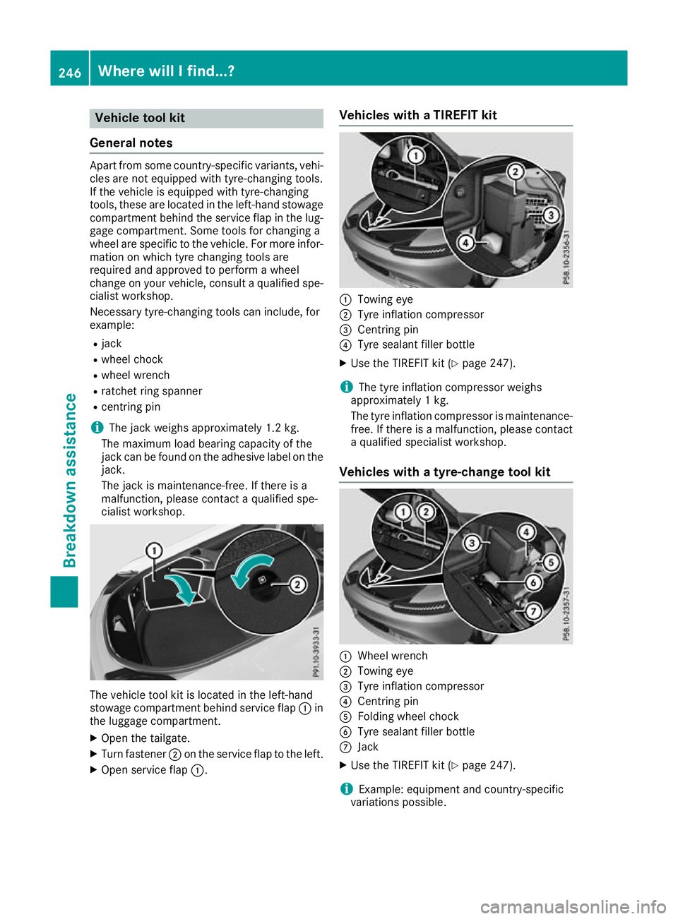
cialist workshop. The vehicle tool kit is located in the left-hand
stowage compartment behind service flap :in
the luggage compartment.
X Open the tailgate.
X Turn fastener ;on the service flap to the left.
X Open service flap :. Vehicles with a TIREFIT kit
:
Towing eye
; Tyre inflation compressor
= Centring pin
? Tyre sealant filler bottle
X Use the TIREFIT kit (Y page 247).
i The tyre inflation compressor weighs
approximately 1 kg.
The tyre inflation compressor is maintenance-
free. If there is a malfunction, please contact a qualified specialist workshop.
Vehicles with a tyre-change tool kit :
Wheel wrench
; Towing eye
= Tyre inflation compressor
? Centring pin
A Folding wheel chock
B Tyre sealant filler bottle
C Jack
X Use the TIREFIT kit (Y page 247).
i Example: equipment and country-specific
variations possible. 246
Where will I find...?Breakdo
wn assis tance
Page 250 of 289
Flat tyre
Preparing the vehicle
Your vehicle may be equipped with: R a TIREFIT kit (Y page 246)
R an emergency spare wheel (certain countries
only) (Y page 273)
Information on changing and fitting a wheel
(Y page 267).
X Stop the vehicle as far away as possible from
traffic on solid, non-slippery and level ground.
X Switch on the hazard warning lamps.
X Safeguard the vehicle against rolling away
(Y page 119).
X If possible, bring the front wheels into the
straight-ahead position.
X Switch off the engine.
X Pump the tyre to the specified tyre pres-
sure: open the driver's door.
The on-board electronics now have status 0.
This is the same as the key having been
removed.
or X Remove the key from the ignition lock.
X Make sure that the passengers are not endan-
gered as they do so. Make sure that no one is
near the danger area while a wheel is being
changed. Anyone who is not directly assisting in the wheel change should, for example,
stand behind the barrier.
X Get out of the vehicle. Pay attention to traffic
conditions when doing so.
X Close the driver's door.
X Place the warning triangle at a suitable dis-
tance (Y page 245). Observe legal require-
ments. TIREFIT kit
Important safety notes TIREFIT is a tyre sealant.
You can use TIREFIT to seal punctures of up to
4 mm, particularly those in the tyre tread. You
can use TIREFIT at outside temperatures down
to Ò20 †. G
WARNING
In the following situations, the tyre sealant is
unable to provide sufficient breakdown assis- tance, as it is unable to seal the tyre properly:
R there are cuts or punctures in the tyre
larger than those mentioned above.
R the wheel rim is damaged.
R you have driven at very low tyre pressures
or on a flat tyre.
There is a risk of an accident.
Do not drive any further. Contact a qualified
specialist workshop. G
WARNING
The tyre sealant is harmful and causes irrita-
tion. It must not come into contact with your
skin, eyes or clothing or be swallowed. Do not inhale TIREFIT fumes. Keep tyre sealant away
from children. There is a risk of injury.
If you come into contact with the tyre sealant,
observe the following:
R Rinse off the tyre sealant from your skin
immediately with water.
R If the tyre sealant comes into contact with
your eyes, immediately rinse them thor-
oughly with clean water.
R If tyre sealant is swallowed, immediately
rinse your mouth out thoroughly and drink
plenty of water. Do not induce vomiting,
and seek medical attention immediately.
R Immediately change out of clothing which
has come into contact with tyre sealant.
R If an allergic reaction occurs, seek medical
attention immediately.
! Do not operate the tyre inflation compres-
sor for longer than ten minutes at a time with- out a break. It may otherwise overheat.
The tyre inflation compressor can be oper-
ated again once it has cooled down.
Comply with the manufacturer's safety instruc-
tions on the tyre inflation compressor label and
on the tyre sealant bottle. Flat tyre
247Breakdown assistance Z
Page 251 of 289
Using the TIREFIT kit
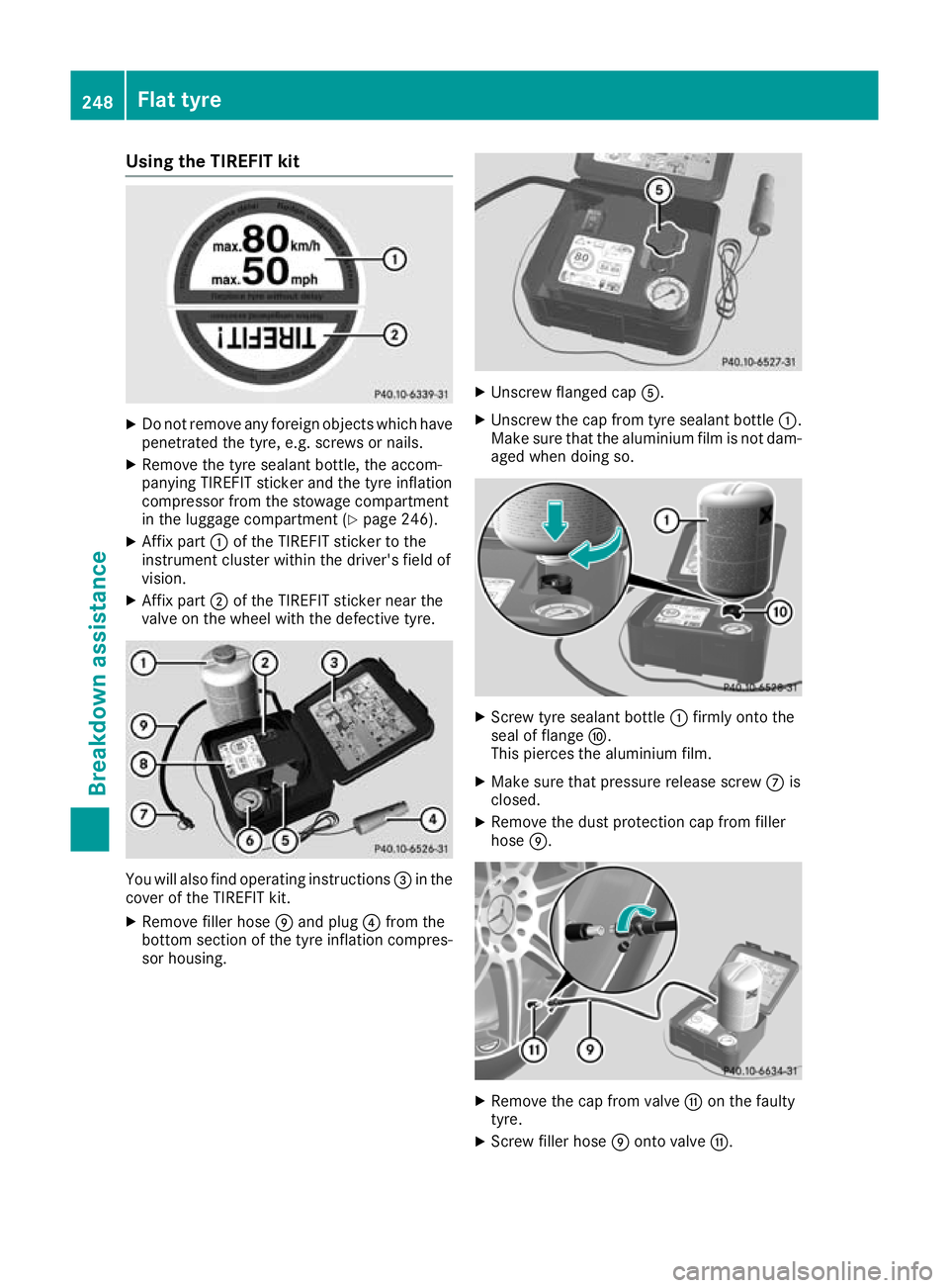
X
Do not remove any foreign objects which have
penetrated the tyre, e.g. screws or nails.
X Remove the tyre sealant bottle, the accom-
panying TIREFIT sticker and the tyre inflation
compressor from the stowage compartment
in the luggage compartment (Y page 246).
X Affix part :of the TIREFIT sticker to the
instrument cluster within the driver's field of
vision.
X Affix part ;of the TIREFIT sticker near the
valve on the wheel with the defective tyre. You will also find operating instructions
=in the
cover of the TIREFIT kit.
X Remove filler hose Eand plug ?from the
bottom section of the tyre inflation compres- sor housing. X
Unscrew flanged cap A.
X Unscrew the cap from tyre sealant bottle :.
Make sure that the aluminium film is not dam-
aged when doing so. X
Screw tyre sealant bottle :firmly onto the
seal of flange F.
This pierces the aluminium film.
X Make sure that pressure release screw Cis
closed.
X Remove the dust protection cap from filler
hose E. X
Remove the cap from valve Gon the faulty
tyre.
X Screw filler hose Eonto valve G. 248
Flat tyreBreakdown assistance