2016 MERCEDES-BENZ AMG GT ROADSTER start stop button
[x] Cancel search: start stop buttonPage 171 of 289
The maximum values of the G-Meter are
saved.
X To reset the G-Meter: pressaagain.
X Using :or9 select Yes
Yes on the steer-
ing wheel.
X Press ato confirm.
The maximum values of the G-Meter are
deleted.
If the ignition remains switched off for longer
than four hours, the G-Meter will be automati-
cally reset.
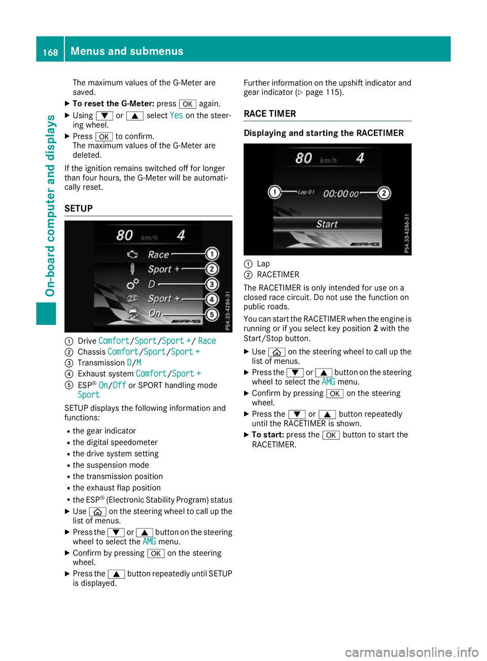
SETUP :
Drive Comfort
Comfort/Sport Sport/Sport +Sport +/ Race
Race
; Chassis Comfort
Comfort/ Sport
Sport/Sport +Sport +
= Transmission D
D/MM
? Exhaust system Comfort
Comfort/Sport +Sport +
A ESP ®
On
On/Off Off or SPORT handling mode
Sport
Sport
SETUP displays the following information and
functions:
R the gear indicator
R the digital speedometer
R the drive system setting
R the suspension mode
R the transmission position
R the exhaust flap position
R the ESP ®
(Electronic Stability Program) status
X Use ò on the steering wheel to call up the
list of menus.
X Press the :or9 button on the steering
wheel to select the AMG
AMGmenu.
X Confirm by pressing aon the steering
wheel.
X Press the 9button repeatedly until SETUP
is displayed. Further information on the upshift indicator and
gear indicator (Y page 115).
RACE TIMER Displaying and starting the RACETIMER
:
Lap
; RACETIMER
The RACETIMER is only intended for use on a
closed race circuit. Do not use the function on
public roads.
You can start the RACETIMER when the engine is running or if you select key position 2with the
Start/Stop button.
X Use ò on the steering wheel to call up the
list of menus.
X Press the :or9 button on the steering
wheel to select the AMG AMGmenu.
X Confirm by pressing aon the steering
wheel.
X Press the :or9 button repeatedly
until the RACETIMER is shown.
X To start: press the abutton to start the
RACETIMER. 168
Menus and submenusOn-board computer and displays
Page 172 of 289
Starting a new lap
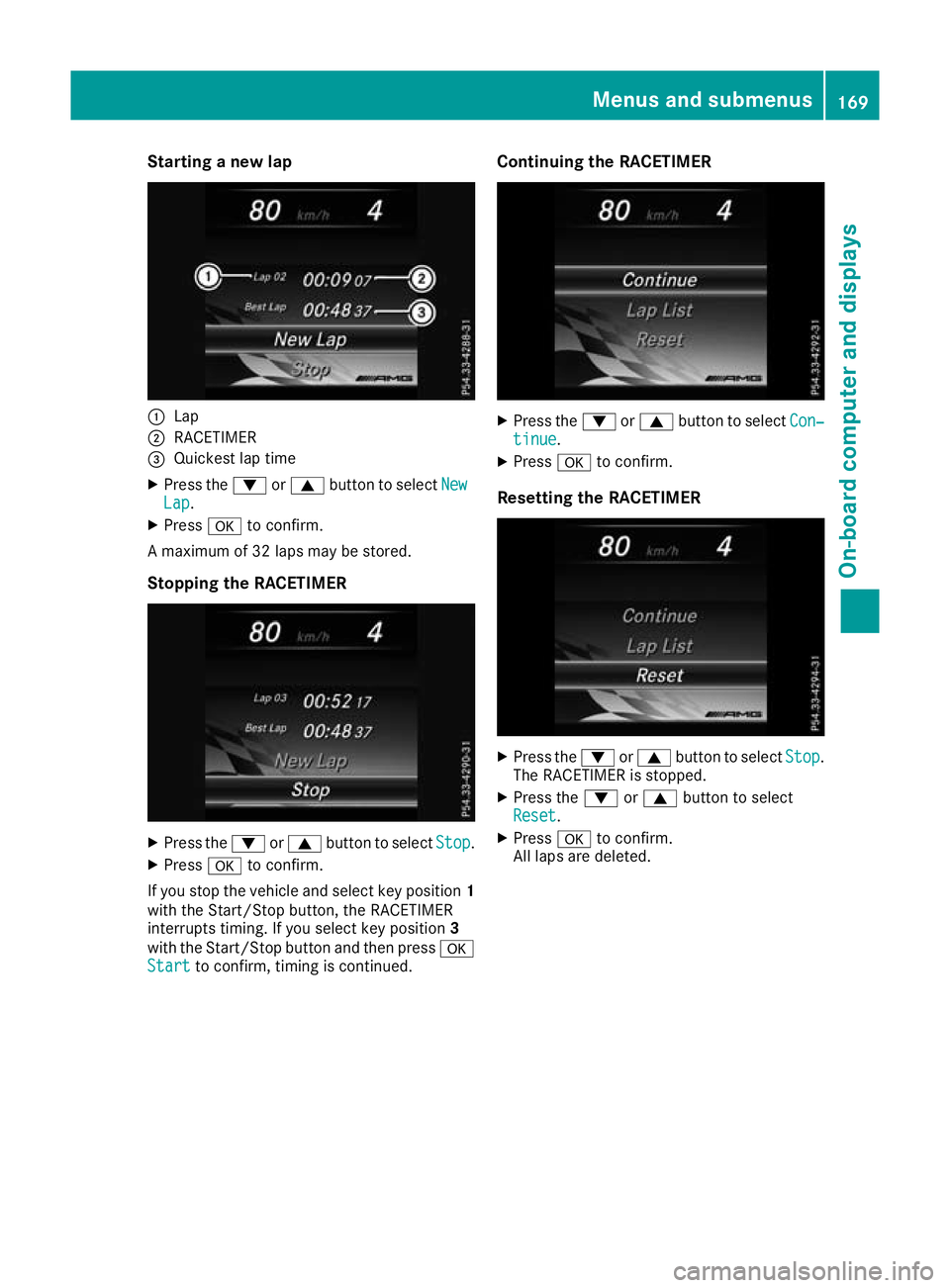
:
Lap
; RACETIMER
= Quickest lap time
X Press the :or9 button to select New
New
Lap
Lap.
X Press ato confirm.
A maximum of 32 laps may be stored.
Stopping the RACETIMER X
Press the :or9 button to select Stop
Stop.
X Press ato confirm.
If you stop the vehicle and select key position 1
with the Start/Stop button, the RACETIMER
interrupts timing. If you select key position 3
with the Start/Stop button and then press a
Start Start to confirm, timing is continued. Continuing the RACETIMER X
Press the :or9 button to select Con‐
Con‐
tinue
tinue.
X Press ato confirm.
Resetting the RACETIMER X
Press the :or9 button to select Stop
Stop.
The RACETIMER is stopped.
X Press the :or9 button to select
Reset
Reset.
X Press ato confirm.
All laps are deleted. Menus and submenus
169On-board computer and displays Z
Page 225 of 289
Cigarette lighter
G
WARNING
You can burn yourself if you touch the hot
heating element or the socket of the cigarette lighter.
In addition, flammable materials can ignite if:
R the hot cigarette lighter falls
R a child holds the hot cigarette lighter to
objects, for example
There is a risk of fire and injury.
Always hold the cigarette lighter by the knob.
Always make sure that the cigarette lighter is
out of reach of children. Never leave children unattended in the vehicle.
Your attention must always be focused on the
traffic conditions. Only use the cigarette lighter when road and traffic conditions permit. X
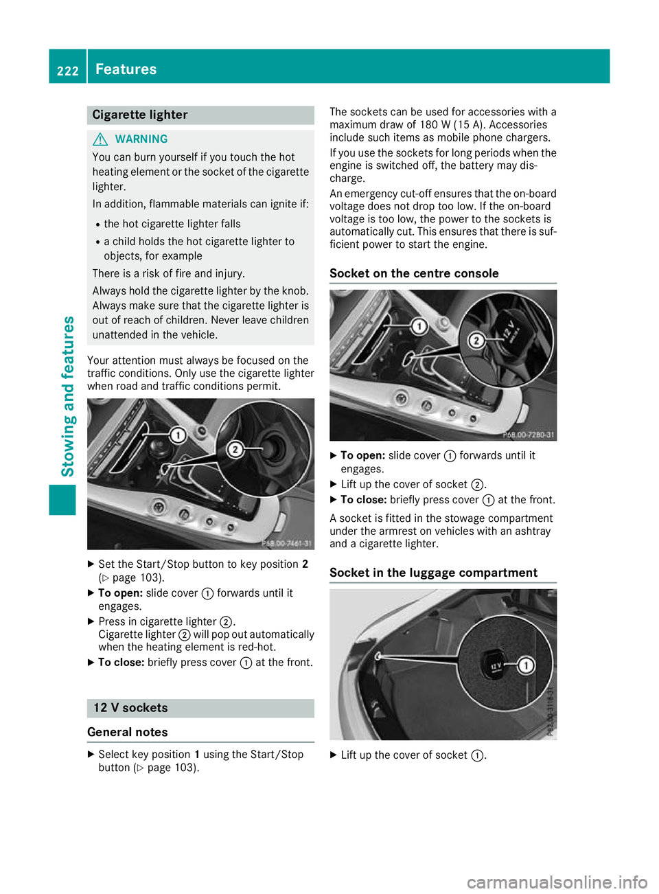
Set the Start/Stop button to key position 2
(Y page 103).
X To open: slide cover :forwards until it
engages.
X Press in cigarette lighter ;.
Cigarette lighter ;will pop out automatically
when the heating element is red-hot.
X To close: briefly press cover :at the front. 12 V sockets
General notes X
Select key position 1using the Start/Stop
button (Y page 103). The sockets can be used for accessories with a
maximum draw of 180 W (15 A). Accessories
include such items as mobile phone chargers.
If you use the sockets for long periods when the engine is switched off, the battery may dis-
charge.
An emergency cut-off ensures that the on-boardvoltage does not drop too low. If the on-board
voltage is too low, the power to the sockets is
automatically cut. This ensures that there is suf-
ficient power to start the engine.
Socket on the centre console X
To open: slide cover :forwards until it
engages.
X Lift up the cover of socket ;.
X To close: briefly press cover :at the front.
A socket is fitted in the stowage compartment
under the armrest on vehicles with an ashtray
and a cigarette lighter.
Socket in the luggage compartment X
Lift up the cover of socket :.222
FeaturesStowing and features
Page 228 of 289
When leaving the vehicle, always take the key
with you and lock the vehicle. Never leave
children unattended in the vehicle.
! Do not enter an automatic car wash with the
rear aerofoil extended. Otherwise, the rear
aerofoil may be damaged.
Only extend the rear aerofoil in order to wash
it by hand. Retract it again when you have fin- ished cleaning it.
You can extend and retract the rear spoiler man-
ually for cleaning.
X Close the tailgate.
X Select key position 2with the Start/Stop but-
ton (Y page 103). X
To extend: press button :.
The rear spoiler is extended.
Button :flashes until the rear spoiler has
extended and then lights up in red.
X To retract: press and hold button :until the
rear spoiler is completely retracted.
Button :flashes until the rear spoiler has
retracted and then goes out.
Rear spoiler retracts manually Rear spoiler retracts manually
appears in the display.
If you release button :while retracting the rear
spoiler, it extends again automatically.
Problems with the rear spoiler Problem
Possible causes/consequences and
M MSolutions The rear spoiler stops
before reaching the end
position when retracting
manually. You have opened the tailgate while manually retracting the rear
spoiler.
X Close the tailgate.
The rear spoiler extends or, if you press and hold the ¬button,
continues retracting. The rear spoiler stops
before reaching the end
position when retract-
ing/extending manually. You have switched off the ignition.
X Switch the ignition back on.
X Press the ¬button.
The rear spoiler extends/retracts. The rear spoiler cannot
be retracted again after
manually extending it. You have opened the tailgate while manually extending the rear
spoiler.
X Close the tailgate. The rear spoiler does not
extend or retract auto-
matically. The rear spoiler's movement is blocked, e.g. by an object jammed
between the body and the rear spoiler.
X Remove the object. Garage door opener
General notes The HomeLink
®
garage door opener integrated
in the rear-view mirror allows you to operate up
to three different door and gate systems.
Once programmed, the integrated garage door
opener in the rear-view mirror will assume the
function of the garage door system's remote control. Please also read the operating instruc-
tions for the garage door system.
When programming a garage door opener, park
the vehicle outside the garage. Do not run the
engine while programming.
The garage door opener is available only for cer- tain countries. Observe the legal requirements
for each individual country. Features
225Stowing and features Z
Page 229 of 289
The HomeLink
®
garage door opener is compat-
ible with most European garage and gate opener
drives.
More information on HomeLink ®
and/or com-
patible products is available:
R at a qualified specialist workshop
R via the HomeLink ®
hotline
(0) 08000 466 354 65 or alternatively
+49 (0) 6838 907-277
R on the Internet at http://www.homelink.com
Important safety notes G
WARNING
When you operate or program the garage door with the integrated garage door opener, per-
sons in the range of movement of the garage
door can become trapped or struck by the
garage door. There is a risk of injury.
When using the integrated garage door
opener, always make sure that nobody is
within the range of movement of the garage
door. G
WARNING
Combustion engines emit poisonous exhaust
gases such as carbon monoxide. Inhaling
these exhaust gases leads to poisoning. There is a risk of fatal injury. Therefore never leave
the engine running in enclosed spaces with-
out sufficient ventilation.
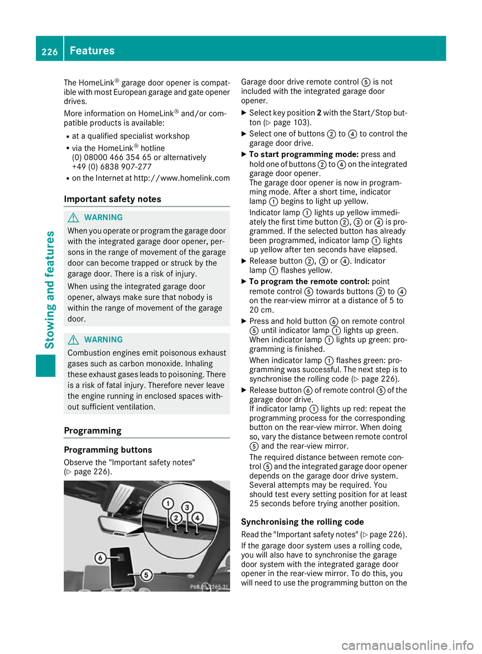
Programming Programming buttons
Observe the "Important safety notes"
(Y page 226). Garage door drive remote control
Ais not
included with the integrated garage door
opener.
X Select key position 2with the Start/Stop but-
ton (Y page 103).
X Select one of buttons ;to? to control the
garage door drive.
X To start programming mode: press and
hold one of buttons ;to? on the integrated
garage door opener.
The garage door opener is now in program-
ming mode. After a short time, indicator
lamp :begins to light up yellow.
Indicator lamp :lights up yellow immedi-
ately the first time button ;,=or? is pro-
grammed. If the selected button has already
been programmed, indicator lamp :lights
up yellow after ten seconds have elapsed.
X Release button ;,=or?. Indicator
lamp :flashes yellow.
X To program the remote control: point
remote control Atowards buttons ;to?
on the rear-view mirror at a distance of 5 to
20 cm.
X Press and hold button Bon remote control
A until indicator lamp :lights up green.
When indicator lamp :lights up green: pro-
gramming is finished.
When indicator lamp :flashes green: pro-
gramming was successful. The next step is to
synchronise the rolling code (Y page 226).
X Release button Bof remote control Aof the
garage door drive.
If indicator lamp :lights up red: repeat the
programming process for the corresponding
button on the rear-view mirror. When doing
so, vary the distance between remote control A and the rear-view mirror.
The required distance between remote con-
trol Aand the integrated garage door opener
depends on the garage door drive system.
Several attempts may be required. You
should test every setting position for at least
25 seconds before trying another position.
Synchronising the rolling code
Read the "Important safety notes" (Y page 226).
If the garage door system uses a rolling code,
you will also have to synchronise the garage
door system with the integrated garage door
opener in the rear-view mirror. To do this, you
will need to use the programming button on the 226
FeaturesStowing and features
Page 230 of 289
door drive control panel. The programming but-
ton may be placed at different locations depend- ing on the manufacturer. It is usually located on
the door drive unit on the garage ceiling.
Familiarise yourself with the garage door drive
operating instructions, e.g. under "Program-
ming of additional remote controls", before car-
rying out the following steps.
Your vehicle must be within range of the garage
door or gate opener drive. Make sure that nei-
ther your vehicle nor any persons/objects are
present within the sweep of the door or gate.
X Select key position 2with the Start/Stop but-
ton (Y page 103).
X Get out of the vehicle.
X Press the programming button on the door
drive unit.
Usually, you now have 30 seconds to initiate
the next step.
X Get into the vehicle.
X Press previously programmed button ;,=
or ? on the integrated garage door opener
repeatedly until the door closes.
Rolling code synchronisation is then com-
plete.
Problems when programming
If you have problems when programming the
integrated garage door opener on the rear-view mirror, please note the following:
R Check the transmitter frequency used by
garage door drive remote control Aand
whether it is supported. The transmitter fre-
quency can usually be found on the back of
remote control Afor the garage door drive.
R Replace the batteries in garage door drive
remote control A. This increases the likeli-
hood that garage door drive remote control
A will transmit a strong and precise signal to
the integrated garage door opener.
R When programming, hold remote control A
at varying distances and angles from but-
tons ;to? that you are programming. Try
various angles at a distance between 5and
20 cm or at the same angle but at varying
distances.
R If another remote control Ais available for
the same garage door drive, perform the pro-
gramming steps again using this remote con- trol A. Before performing these steps, make
sure that new batteries have been fitted in
garage door drive remote control A.R
Note that some remote controls transmit only
for a limited period (the indicator lamp on theremote control goes out). Press button Bon
remote control Aagain before transmission
ends.
R Align the aerial cable of the garage door
opener unit. This can improve signal recep-
tion/transmission.
Opening/closing the garage door Once programmed, the integrated garage door
opener will assume the function of the garage
door system's remote control. Please also read
the operating instructions for the garage door
system.
X Select key position 2with the Start/Stop but-
ton (Y page 103).
X Press button ;,=or? that you have pro-
grammed to operate the garage door.
Garage door system with a fixed code: indi-
cator lamp :lights up green.
Garage door system with a rolling code: indi-
cator lamp :flashes green.
The transmitter will transmit a signal for as
long as the button is pressed. The transmis-
sion is halted after a maximum of ten seconds and indicator lamp :lights up yellow.
X Press button ;,=or? again if necessary.
Clearing the memory Make sure that you clear the memory of the
integrated garage door opener before selling the
vehicle.
X Select key position 2with the Start/Stop but-
ton (Y page 103).
X Press and hold buttons ;and ?.
The indicator lamp initially lights up yellow
and then green.
X Release buttons ;and ?.
The memory of the integrated garage door
opener in the rear-view mirror is cleared. Features
227Stowing and features Z
Page 237 of 289
Checking the oil level using the on-board computer
X
Select key position 2with the Start/Stop button.
X Use ò on the steering wheel to call up the list of menus.
X Press the :or9 button on the steering wheel to select the Service
Servicemenu.
X Confirm by pressing aon the steering wheel.
X Use : or9 to select the Engine oil level:
Engine oil level: submenu.
X Press ato confirm the selection.
The Engine oil level Measuring now Measurement accurate only if vehicle is
Engine oil level Measuring now Measurement accurate only if vehicle is
level
level message appears in the multifunction display.
The measurement takes a few seconds. You will see one of the following messages in the multi-
function display: Display messages
Possible causes/consequences and
M
MSolutions Engine oil level OK
Engine oil level OK The oil level is correct.
Add 1 litre engine
Add 1 litre engine
oil when next refu‐ oil when next refu‐
elling elling The oil level is too low.
X Top up 1.0 litre of engine oil. Engine oil level
Engine oil level
Reduce oil level Reduce oil level The engine oil level is too high.
X Have excess engine oil siphoned off. For engine oil
For engine oil
level turn on igni‐ level turn on igni‐
tion tion The ignition is switched off.
X Select key position 2with the Start/Stop button. Waiting period for
Waiting period for
engine oil level engine oil level
not observed not observed The required waiting period was not observed.
X The engine must be at normal operating temperature.
Measurements can only be taken within the first 4 minutes after the
engine has been switched off. Engine oil level Engine oil level
Not Not
with
with the
theengine
engine
running
running The engine is running; oil level measurement is not possible.
X Switch off the engine.
X Repeat the measurement. Observe the required waiting period. Engine oil level
Engine oil level
Correct Correct
measurement
measurement
only if vehicle is
only if vehicle is
on level ground on level ground The vehicle is not parked on a level surface.
X Park the vehicle on a level surface. Engine oil level
Engine oil level
cannot be measured. cannot be measured. The oil level measurement with the oil dipstick is possible. The meas-
uring system is malfunctioning.
X Consult a qualified specialist workshop. Topping up engine oil
G
WARNING
Certain components in the engine compart-
ment could be very hot, e.g. the engine, the
radiator and parts of the exhaust system. There is a risk of injury when accessing the
engine compartment.
As far as possible, allow the engine to cool
down and only touch the components descri- bed in the following. 234
Engine compartmentMaintenance and care
Page 239 of 289
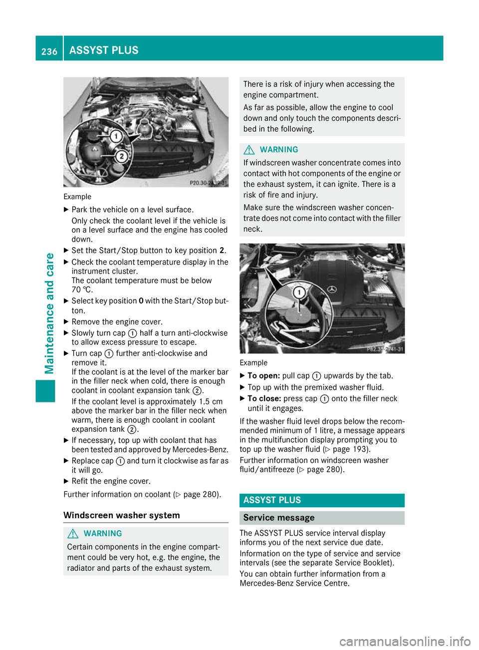
Example
X Park the vehicle on a level surface.
Only check the coolant level if the vehicle is
on a level surface and the engine has cooled
down.
X Set the Start/Stop button to key position 2.
X Check the coolant temperature display in the
instrument cluster.
The coolant temperature must be below
70 †.
X Select key position 0with the Start/Stop but-
ton.
X Remove the engine cover.
X Slowly turn cap :half a turn anti-clockwise
to allow excess pressure to escape.
X Turn cap :further anti-clockwise and
remove it.
If the coolant is at the level of the marker bar
in the filler neck when cold, there is enough
coolant in coolant expansion tank ;.
If the coolant level is approximately 1.5 cm
above the marker bar in the filler neck when
warm, there is enough coolant in coolant
expansion tank ;.
X If necessary, top up with coolant that has
been tested and approved by Mercedes-Benz.
X Replace cap :and turn it clockwise as far as
it will go.
X Refit the engine cover.
Further information on coolant (Y page 280).
Windscreen washer system G
WARNING
Certain components in the engine compart-
ment could be very hot, e.g. the engine, the
radiator and parts of the exhaust system. There is a risk of injury when accessing the
engine compartment.
As far as possible, allow the engine to cool
down and only touch the components descri- bed in the following. G
WARNING
If windscreen washer concentrate comes into contact with hot components of the engine or
the exhaust system, it can ignite. There is a
risk of fire and injury.
Make sure the windscreen washer concen-
trate does not come into contact with the filler neck. Example
X To open: pull cap:upwards by the tab.
X Top up with the premixed washer fluid.
X To close: press cap :onto the filler neck
until it engages.
If the washer fluid level drops below the recom- mended minimum of 1 litre, a message appears
in the multifunction display prompting you to
top up the washer fluid (Y page 193).
Further information on windscreen washer
fluid/antifreeze (Y page 280). ASSYST PLUS
Service message
The ASSYST PLUS service interval display
informs you of the next service due date.
Information on the type of service and service
intervals (see the separate Service Booklet).
You can obtain further information from a
Mercedes-Benz Service Centre. 236
ASSYST PLUSMaintenance and care