Page 662 of 723
CavityCartridge Fuse Micro Fuse Description
F24 30 Amp Pink –Driver Door Module
F25 30 Amp Pink –Front Wipers
F26 30 Amp Pink –Anti-lock Brakes/Stability Control
Module/Valves
F28 20 Amp Blue –Trailer Tow Backup Lights - If Equipped
F29 20 Amp Blue –Trailer Tow Parking Lights - If Equipped
F30 30 Amp Pink –Trailer Tow Receptacle - If Equipped
F32 30 Amp Pink –Drive Train Control Module
F34 30 Amp Pink –Slip Differential Control
F35 30 Amp Pink –Sunroof - If Equipped
F36 30 Amp Pink –Rear Defroster
F37 25 Amp Clear –Rear Blower Motor - If Equipped
F38 30 Amp Pink –Power Inverter 115V AC - If Equipped
F39 30 Amp Pink –Power Liftgate - If Equipped
660 MAINTAINING YOUR VEHICLE
Page 663 of 723
CavityCartridge Fuse Micro Fuse Description
F40 –10 Amp Red Daytime Running Lights/Headlamp Lev-
eling
F42 –20 Amp Yellow Horn
F44 –10 Amp Red Diagnostic Port
F49 –10 Amp Red Integrated Central Stack / Climate Control
F50 –20 Amp Yellow Air Suspension Control Module - If
Equipped
F51 –15 Amp Blue Ignition Node Module / Keyless Ignition
/ Steering Column Lock
F52 –5 Amp Tan Battery Sensor
F53 –20 Amp Yellow Trailer Tow – Left Turn/Stop Lights - If
Equipped
F56 –15 Amp Blue Additional Content (Diesel engine only)
F57 –20 Amp Yellow NOX Sensor
F58 –15 Amp Blue HID Headlamps LH - If Equipped
7
MAINTAINING YOUR VEHICLE 661
Page 665 of 723
CavityCartridge Fuse Micro Fuse Description
F72 –10 Amp Red PCM (If Equipped)
F73 –15 Amp Blue HID Headlamp RH - If Equipped
F75 –10 Amp Red Dual Batt Control (If Equipped)
F76 –10 Amp Red Anti-lock Brakes/Electronic Stability Con-
trol
F77 –10 Amp Red Drivetrain Control Module/Front Axle
Disconnect Module
F78 –10 Amp Red Engine Control Module / Electric Power
Steering
F80 –10 Amp Red Universal Garage Door Opener / Compass
/ Anti-Intrusion Module
F81 –20 Amp Yellow Trailer Tow Right Turn/Stop Lights
F82 –10 Amp Red Steering Column Control Module/ Cruise
Control / DTV
F83 –10 Amp Red Fuel Door
7
MAINTAINING YOUR VEHICLE 663
Page 672 of 723

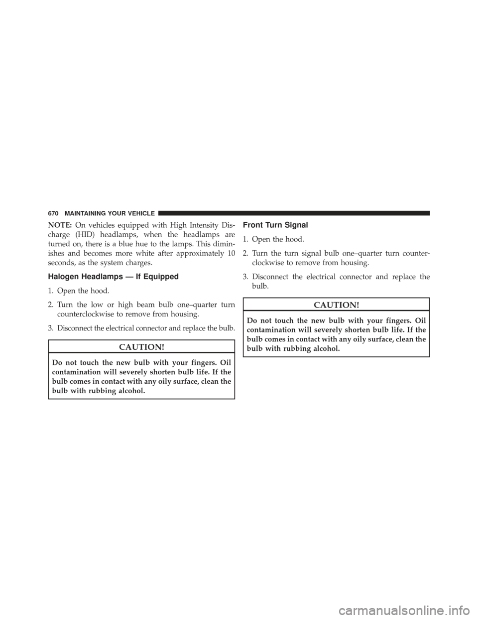
NOTE:On vehicles equipped with High Intensity Dis-
charge (HID) headlamps, when the headlamps are
turned on, there is a blue hue to the lamps. This dimin-
ishes and becomes more white after approximately 10
seconds, as the system charges.
Halogen Headlamps — If Equipped
1. Open the hood.
2. Turn the low or high beam bulb one–quarter turn counterclockwise to remove from housing.
3.
Disconnect the electrical connector and replace the bulb.
CAUTION!
Do not touch the new bulb with your fingers. Oil
contamination will severely shorten bulb life. If the
bulb comes in contact with any oily surface, clean the
bulb with rubbing alcohol.
Front Turn Signal
1. Open the hood.
2. Turn the turn signal bulb one–quarter turn counter- clockwise to remove from housing.
3. Disconnect the electrical connector and replace the bulb.
CAUTION!
Do not touch the new bulb with your fingers. Oil
contamination will severely shorten bulb life. If the
bulb comes in contact with any oily surface, clean the
bulb with rubbing alcohol.
670 MAINTAINING YOUR VEHICLE
Page 673 of 723

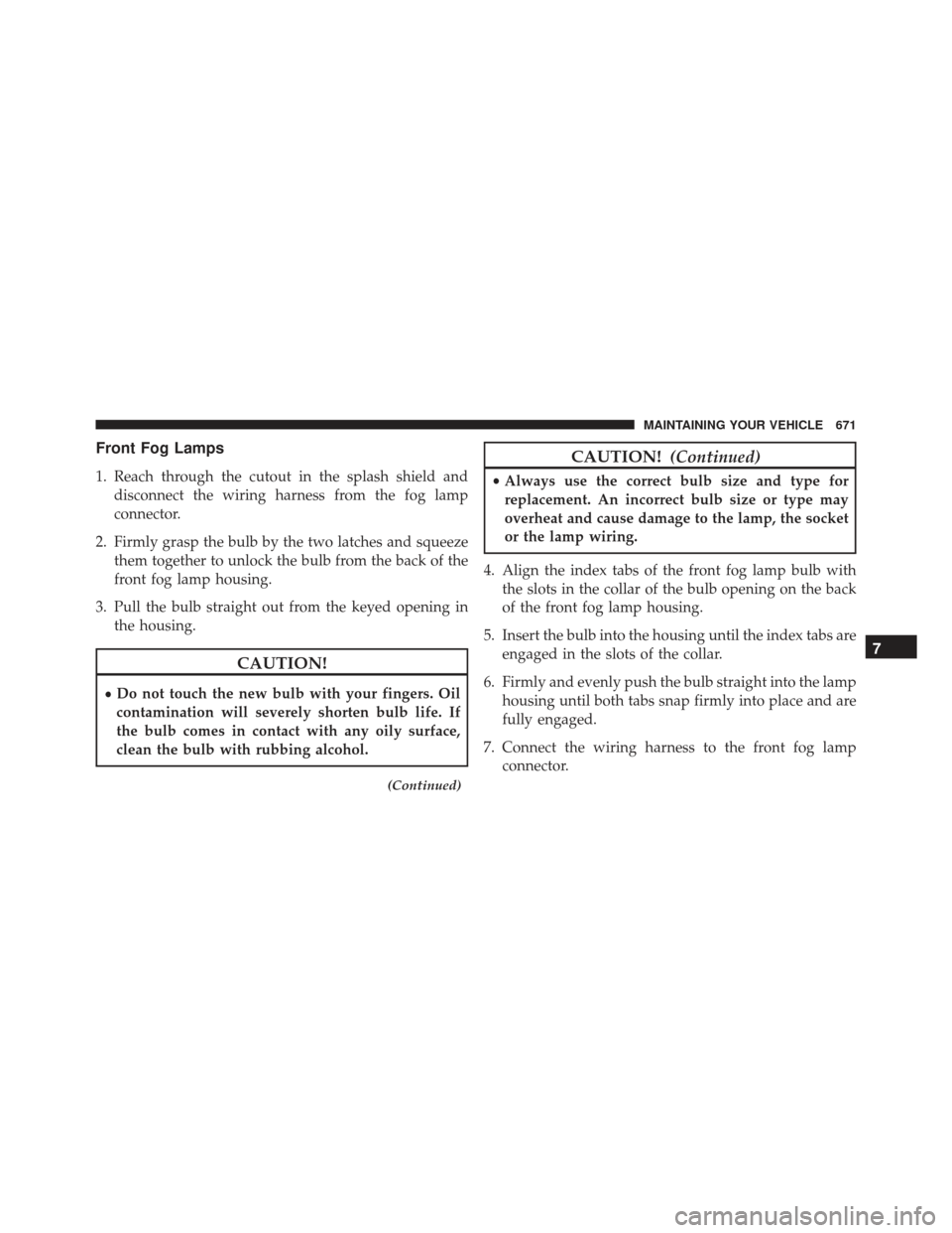
Front Fog Lamps
1. Reach through the cutout in the splash shield anddisconnect the wiring harness from the fog lamp
connector.
2. Firmly grasp the bulb by the two latches and squeeze them together to unlock the bulb from the back of the
front fog lamp housing.
3. Pull the bulb straight out from the keyed opening in the housing.
CAUTION!
•Do not touch the new bulb with your fingers. Oil
contamination will severely shorten bulb life. If
the bulb comes in contact with any oily surface,
clean the bulb with rubbing alcohol.
(Continued)
CAUTION!
(Continued)
•Always use the correct bulb size and type for
replacement. An incorrect bulb size or type may
overheat and cause damage to the lamp, the socket
or the lamp wiring.
4. Align the index tabs of the front fog lamp bulb with the slots in the collar of the bulb opening on the back
of the front fog lamp housing.
5. Insert the bulb into the housing until the index tabs are engaged in the slots of the collar.
6. Firmly and evenly push the bulb straight into the lamp housing until both tabs snap firmly into place and are
fully engaged.
7. Connect the wiring harness to the front fog lamp connector.
7
MAINTAINING YOUR VEHICLE 671
Page 674 of 723
Rear Tail, Stop, Turn Signal, And Backup Lamps
1. Raise the liftgate.
2. Remove the two push-pins from the tail lamp housing.
3. Grasp the tail lamp and pull firmly rearward todisengage the lamp from the aperture panel. 4. Twist socket counter clockwise and remove from
lamp.
5. Pull the bulb to remove it from the socket.
6. Replace the bulb, reinstall the socket, and reattach the lamp assembly.
Rear Liftgate Mounted Tail Lamp
1. Raise the liftgate.
2. Use a fiber stick or flat blade screw driver to pry thelower trim from the liftgate.
3. Continue removing the trim.
4. Disconnect the two trim panel lights.
Tail Lamp Push Pins
672 MAINTAINING YOUR VEHICLE
Page 675 of 723
5. Tail lamps are now visible. Rotate socket(s) counterclockwise.
Rear Liftgate Tail LampsRear Of Liftgate Tail Lamp
1 — Auxiliary LED Tail Connector – Do Not Remove
2 — Backup Bulb Socket
7
MAINTAINING YOUR VEHICLE 673
Page 703 of 723

Alarm (Security Alarm)............20, 297, 302, 322
Alarm System (Security Alarm) ................20
Alterations/Modifications, Vehicle ...............9
Antifreeze (Engine Coolant) ...............641, 675
Disposal ............................. .643
Anti-Lock Brake System (ABS) ................502
Anti-Lock Warning Light ....................311
Appearance Care ........................ .651
Arming System (Security Alarm) ...............20
Assist, Hill Start ......................... .504
Auto Down Power Windows ..................44
Automatic Door Locks ......................35
Automatic Headlights ..................... .170
Automatic High Beams .....................170
Automatic Temperature Control (ATC) .......425, 433
Automatic Transmission .................471, 651
Adding Fluid ......................... .651
Autostick ............................ .479
Fluid And Filter Changes ..................651 Fluid Change
......................... .651
Fluid Level Check ...................649, 650
Fluid Type ........................ .649, 677
Gear Ranges .......................... .473
Special Additives ...................... .650
Autostick .............................. .479
Auxiliary Electrical Outlet (Power Outlet) ........263
Auxiliary Power Outlet .....................263
Axle Fluid ............................. .677
Battery ............................ .299, 623
Charging System Light ...................299
Keyless Transmitter Replacement (RKE) ........26
Belts, Seat ...............................111
Blind Spot Monitoring ..................... .134
Body Mechanism Lubrication .................629
B-Pillar Location ......................... .528
Brake Assist System ...................... .504
Brake Control System, Electronic ..............501
10
INDEX 701