2016 JEEP CHEROKEE charging
[x] Cancel search: chargingPage 3 of 236

INTRODUCTION/WELCOME
WELCOME FROM FCA US LLC...... 3
CONTROLS AT A GLANCE
DRIVER COCKPIT.............. 6
INSTRUMENT CLUSTER .......... 8
GETTING STARTED
KEYFOB ................... 10
REMOTE START............... 12
VEHICLE SECURITY ALARM ....... 12
KEYLESS ENTER-N-GO .......... 13
SEAT BELT SYSTEMS ........... 16
SUPPLEMENTAL RESTRAINT
SYSTEM (SRS) — AIR BAGS ....... 17
CHILD RESTRAINTS ............ 25
HEAD RESTRAINTS ............. 30
FRONT SEATS ................ 32
REAR SEATS ................ 35
HEATED/VENTILATED SEATS ....... 37
HEATED STEERING WHEEL ........ 38
TILT/TELESCOPING STEERING
COLUMN ................... 39
OPERATING YOUR VEHICLE
ENGINE BREAK-IN
RECOMMENDATIONS ........... 40
TURN SIGNAL/HIGH BEAM LEVER . . . 40
HEADLIGHT SWITCH ............ 41
WIPER/WASHER LEVER .......... 42
ELECTRONIC SPEED CONTROL ..... 43
ADAPTIVE CRUISE CONTROL (ACC) . . . 45
FORWARD COLLISION WARNING
(FCW) WITH MITIGATION ......... 49
MANUAL CLIMATE CONTROLS
WITHOUT TOUCHSCREEN ........ 51
MANUAL CLIMATE CONTROLS
WITH TOUCHSCREEN ........... 52
AUTOMATIC TEMPERATURE
CONTROLS (ATC) .............. 55
STOP/START SYSTEM — IF EQUIPPED . . 59ELECTRIC PARK BRAKE (EPB) ...... 60
PARKSENSE ................. 62
LANESENSE ................. 64
PARKVIEW REAR BACK UP CAMERA... 64
POWER SUNROOF ............. 66
WIND BUFFETING ............. 69
ELECTRONICS
YOUR VEHICLE'S SOUND SYSTEM . . . 70
IDENTIFYING YOUR RADIO ........ 72
UCONNECT ACCESS ............ 73
UCONNECT 5.0 ............... 85
UCONNECT 8.4A/8.4AN .......... 97
UCONNECT 8.4A/8.4AN VOICE
RECOGNITION QUICK TIPS ....... 112
UCONNECT PHONE ........... 131
STEERING WHEEL AUDIO
CONTROLS ................. 142
ELECTRONIC VEHICLE INFORMATION
CENTER (EVIC) AND DRIVER
INFORMATION DISPLAY (DID) ..... 142
PROGRAMMABLE FEATURES ...... 143
UNIVERSAL GARAGE DOOR OPENER
(HomeLink) ................. 144
POWER INVERTER ............ 147
POWER OUTLET ............. 148
WIRELESS CHARGING PAD ....... 150
OFF-ROAD CAPABILITIES
FOUR-WHEEL DRIVE OPERATION . . . 153
SELEC-TERRAIN............. 156
UTILITY
CARGO AREA FEATURES ........ 157
TRAILER TOWING ............ 158
RECREATIONAL TOWING
(BEHIND MOTORHOME, ETC.) ..... 158
WHAT TO DO IN EMERGENCIES
ROADSIDE ASSISTANCE......... 163
INSTRUMENT CLUSTER WARNING
LIGHTS ................... 163
INSTRUMENT CLUSTER INDICATOR
LIGHTS ................... 170
IF YOUR ENGINE OVERHEATS ..... 173
TIRESERVICEKIT ............ 174
JACKING AND TIRE CHANGING .... 180
JUMP-STARTING PROCEDURES .... 186
FREEING A STUCK VEHICLE ...... 189
RECOVERY STRAP — IF EQUIPPED . . . 190SHIFT LEVER OVERRIDE........ 190
TOWING A DISABLED VEHICLE .... 191
ENHANCED ACCIDENT RESPONSE
SYSTEM (EARS) .............. 192
EVENT DATA RECORDER (EDR) .... 192
TABLE OF CONTENTS
Page 152 of 236

WIRELESS CHARGING PAD
Wireless Charging Pad — If Equipped
Your vehicle may be equipped with a wireless charging pad located inside the upper
portion of the center console. This charging pad is designed to wirelessly charge your
Qi enabled mobile phone. Qi is a standard that uses magnetic induction to transfer
power to your mobile device.
Your mobile phone must be designed for
Qi wireless charging, be equipped with
an aftermarket sleeve or equipped with a
back plate from your mobile phone pro-
vider, or an online or local electronics
retailer. The wireless charging pad is
equipped with an anti-slip mat, an ad-
justable cradle to hold your mobile phone
in place and an LED indicator light.
NOTE:
Visit UconnectPhone.com for supported
mobile phones and compatible aftermar-
ket sleeves.
Wireless Charging Pad
ELECTRONICS
150
Page 153 of 236

Wireless Charging Pad Operation
To use the wireless charging pad, the coil in your mobile phone needs to align with
the coil in the charging pad, which is located directly under the Qi logo. Since each
mobile phone’s coil location is different, you may need a few attempts to locate the
correct spot for your mobile phone:
1. Place your mobile phone on the wireless charging pad, towards the Qi logo, so thatthe LED turns red. If the LED does not turn red, pick up the mobile phone and
change it’s location.
NOTE:
The mobile phone mustbe aligned around
the Qi logo for the LED to transition from
red to flashing green.
2. Once the LED transitions from red to flashing green, your mobile phone is
correctly placed and charging.
3. If the LED does not transition from red to flashing green, and just turns off,
pick up your mobile phone and repo-
sition it on the charging pad.
Mobile Phone Alignment
ELECTRONICS
151
Page 154 of 236

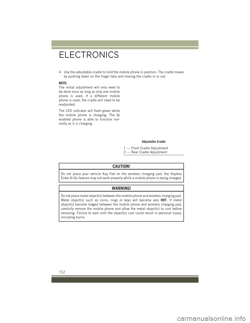
4. Use the adjustable cradle to hold the mobile phone in position. The cradle movesby pushing down on the finger tabs and moving the cradle in or out.
NOTE:
The initial adjustment will only need to
be done once as long as only one mobile
phone is used. If a different mobile
phone is used, the cradle will need to be
readjusted.
The LED indicator will flash green while
the mobile phone is charging. The Qi
enabled phone is able to function nor-
mally as it is charging.
CAUTION!
Do not place your vehicle Key Fob on the wireless charging pad, the Keyless
Enter-N-Go feature may not work properly while a mobile phone is being charged.
WARNING!
Do not place metal object(s) between the mobile phone and wireless charging pad.
Metal object(s) such as coins, rings or keys will become very HOT. If metal
object(s) become lodged between the mobile phone and wireless charging pad,
carefully remove the mobile phone and allow the metal object(s) to cool before
removing. Failure to wait until the object(s) cool could result in personal injury,
including burns.
Adjustable Cradle
1 — Front Cradle Adjustment
2 — Rear Cradle Adjustment
ELECTRONICS
152
Page 165 of 236

ROADSIDE ASSISTANCE
Dial toll-free 1-800-521-2779 for U.S. Residents or 1-800-363-4869 for Canadian
Residents.
• Provide your name, vehicle identification number, license plate number, and yourlocation, including the telephone number from which you are calling.
• Briefly describe the nature of the problem and answer a few simple questions.
• You will be given the name of the service provider and an estimated time of arrival. If you feel you are in an “unsafe situation”, please let us know. With your consent,
we will contact local police or safety authorities.
INSTRUMENT CLUSTER WARNING LIGHTS
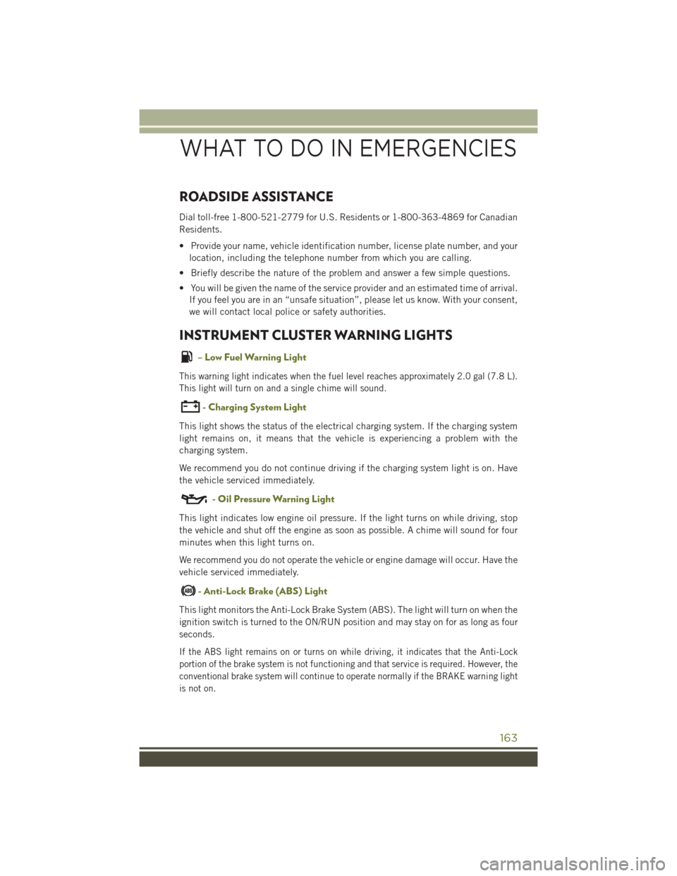
– Low Fuel Warning Light
This warning light indicates when the fuel level reaches approximately 2.0 gal (7.8 L).
This light will turn on and a single chime will sound.
- Charging System Light
This light shows the status of the electrical charging system. If the charging system
light remains on, it means that the vehicle is experiencing a problem with the
charging system.
We recommend you do not continue driving if the charging system light is on. Have
the vehicle serviced immediately.
- Oil Pressure Warning Light
This light indicates low engine oil pressure. If the light turns on while driving, stop
the vehicle and shut off the engine as soon as possible. A chime will sound for four
minutes when this light turns on.
We recommend you do not operate the vehicle or engine damage will occur. Have the
vehicle serviced immediately.
- Anti-Lock Brake (ABS) Light
This light monitors the Anti-Lock Brake System (ABS). The light will turn on when the
ignition switch is turned to the ON/RUN position and may stay on for as long as four
seconds.
If the ABS light remains on or turns on while driving, it indicates that the Anti-Lock
portion of the brake system is not functioning and that service is required. However, the
conventional brake system will continue to operate normally if the BRAKE warning light
is not on.
WHAT TO DO IN EMERGENCIES
163
Page 189 of 236

Preparations For Jump-Start
The battery in your vehicle is located in the front of the engine compartment, behind
the left headlight assembly.
NOTE:
The positive battery post is covered with a protective cap. Lift up on the cap to gain
access to the positive battery post.
WARNING!
• Take care to avoid the radiator cooling fan whenever the hood is raised. It canstart anytime the ignition switch is ON. You can be injured by moving fan
blades.
• Remove any metal jewelry such as rings, watch bands and bracelets that could
make an inadvertent electrical contact. You could be seriously injured.
• Batteries contain sulfuric acid that can burn your skin or eyes and generate
hydrogen gas which is flammable and explosive. Keep open flames or sparks
away from the battery.
1. Set the parking brake, shift the automatic transmission into PARK and turn the ignition to LOCK.
2. Turn off the heater, radio, and all unnecessary electrical accessories.
3. If using another vehicle to jump-start the battery, park the vehicle within the jumper cables reach, set the parking brake and make sure the ignition is OFF.
WARNING!
Do not allow vehicles to touch each other as this could establish a ground
connection and personal injury could result.
Jump Starting Procedure
WARNING!
Failure to follow this jump-starting procedure could result in personal injury or
property damage due to battery explosion.
CAUTION!
Failure to follow these procedures could result in damage to the charging system
of the booster vehicle or the discharged vehicle.
WHAT TO DO IN EMERGENCIES
187
Page 190 of 236

Connecting The Jumper Cables
1. Connect the positive(+)end of the jumper cable to the positive (+)post of the
discharged vehicle.
2. Connect the opposite end of the positive (+)jumper cable to the positive (+)post
of the booster battery.
3. Connect the negative (-)end of the jumper cable to the negative (-)post of the
booster battery.
4. Connect the opposite end of the negative (-)jumper cable to a good engine ground
(exposed metal part of the discharged vehicle’s engine) away from the battery and
the fuel injection system.
WARNING!
Do not connect the jumper cable to the negative (-) post of the discharged battery.
The resulting electrical spark could cause the battery to explode and could result
in serious injury. Only use the specific ground point, do not use any other exposed
metal parts.
5. Start the engine in the vehicle that has the booster battery, let the engine idle a few minutes, and then start the engine in the vehicle with the discharged battery.
6. Once the engine is started, remove the jumper cables in the reverse sequence:
Disconnecting The Jumper Cables
1. Disconnect the negative (-)end of the jumper cable from the engine ground of the
vehicle with the discharged battery.
2. Disconnect the opposite end of the negative (-)jumper cable from the negative (-)
post of the booster battery.
3. Disconnect the positive (+)end of the jumper cable from the positive (+)post of
the booster battery.
4. Disconnect the opposite end of the positive (+)jumper cable from the positive (+)
post of the vehicle with the discharged battery.
If frequent jump starting is required to start your vehicle you should have the battery
and charging system inspected at your authorized dealer.
CAUTION!
Accessories plugged into the vehicle power outlets draw power from the vehicle’s
battery, even when not in use (i.e., cellular devices, etc.). Eventually, if plugged in
long enough without engine operation, the vehicle’s battery will discharge suffi-
ciently to degrade battery life and/or prevent the engine from starting.
WHAT TO DO IN EMERGENCIES
188
Page 211 of 236

Interior Fuses
The interior fuse panel is located in the passenger compartment on the left side dash
panel under the instrument panel.
CavityBlade Fuse Description
F13 15 Amp Blue Low Beam Left
F32 10 Amp Red Interior Lighting
F36 10 Amp Red Intrusion Module/Siren – If Equipped
F38 20 Amp Yellow Deadbolt All Unlock
F43 20 Amp Yellow Washer Pump Front
F48 25 Amp Clear Fog Lamp Rear Left/Right – If Equipped
F49 7.5 Amp Brown Lumbar Support
F50 7.5 Amp Brown Wireless Charging Pad – If Equipped
F51 10 Amp Red Driver Window Switch/Power Mirrors –
If Equipped
F53 7.5 Amp Brown UCI Port (USB & AUX)
F89 10 Amp Red Door Locks – Driver Unlock
F91 7.5 Amp Brown Fog Lamp Front Left
F92 7.5 Amp Brown Fog Lamp Front Right
F93 10 Amp Red Low Beam Right
MAINTAINING YOUR VEHICLE
209