2016 JEEP CHEROKEE park assist
[x] Cancel search: park assistPage 3 of 236

INTRODUCTION/WELCOME
WELCOME FROM FCA US LLC...... 3
CONTROLS AT A GLANCE
DRIVER COCKPIT.............. 6
INSTRUMENT CLUSTER .......... 8
GETTING STARTED
KEYFOB ................... 10
REMOTE START............... 12
VEHICLE SECURITY ALARM ....... 12
KEYLESS ENTER-N-GO .......... 13
SEAT BELT SYSTEMS ........... 16
SUPPLEMENTAL RESTRAINT
SYSTEM (SRS) — AIR BAGS ....... 17
CHILD RESTRAINTS ............ 25
HEAD RESTRAINTS ............. 30
FRONT SEATS ................ 32
REAR SEATS ................ 35
HEATED/VENTILATED SEATS ....... 37
HEATED STEERING WHEEL ........ 38
TILT/TELESCOPING STEERING
COLUMN ................... 39
OPERATING YOUR VEHICLE
ENGINE BREAK-IN
RECOMMENDATIONS ........... 40
TURN SIGNAL/HIGH BEAM LEVER . . . 40
HEADLIGHT SWITCH ............ 41
WIPER/WASHER LEVER .......... 42
ELECTRONIC SPEED CONTROL ..... 43
ADAPTIVE CRUISE CONTROL (ACC) . . . 45
FORWARD COLLISION WARNING
(FCW) WITH MITIGATION ......... 49
MANUAL CLIMATE CONTROLS
WITHOUT TOUCHSCREEN ........ 51
MANUAL CLIMATE CONTROLS
WITH TOUCHSCREEN ........... 52
AUTOMATIC TEMPERATURE
CONTROLS (ATC) .............. 55
STOP/START SYSTEM — IF EQUIPPED . . 59ELECTRIC PARK BRAKE (EPB) ...... 60
PARKSENSE ................. 62
LANESENSE ................. 64
PARKVIEW REAR BACK UP CAMERA... 64
POWER SUNROOF ............. 66
WIND BUFFETING ............. 69
ELECTRONICS
YOUR VEHICLE'S SOUND SYSTEM . . . 70
IDENTIFYING YOUR RADIO ........ 72
UCONNECT ACCESS ............ 73
UCONNECT 5.0 ............... 85
UCONNECT 8.4A/8.4AN .......... 97
UCONNECT 8.4A/8.4AN VOICE
RECOGNITION QUICK TIPS ....... 112
UCONNECT PHONE ........... 131
STEERING WHEEL AUDIO
CONTROLS ................. 142
ELECTRONIC VEHICLE INFORMATION
CENTER (EVIC) AND DRIVER
INFORMATION DISPLAY (DID) ..... 142
PROGRAMMABLE FEATURES ...... 143
UNIVERSAL GARAGE DOOR OPENER
(HomeLink) ................. 144
POWER INVERTER ............ 147
POWER OUTLET ............. 148
WIRELESS CHARGING PAD ....... 150
OFF-ROAD CAPABILITIES
FOUR-WHEEL DRIVE OPERATION . . . 153
SELEC-TERRAIN............. 156
UTILITY
CARGO AREA FEATURES ........ 157
TRAILER TOWING ............ 158
RECREATIONAL TOWING
(BEHIND MOTORHOME, ETC.) ..... 158
WHAT TO DO IN EMERGENCIES
ROADSIDE ASSISTANCE......... 163
INSTRUMENT CLUSTER WARNING
LIGHTS ................... 163
INSTRUMENT CLUSTER INDICATOR
LIGHTS ................... 170
IF YOUR ENGINE OVERHEATS ..... 173
TIRESERVICEKIT ............ 174
JACKING AND TIRE CHANGING .... 180
JUMP-STARTING PROCEDURES .... 186
FREEING A STUCK VEHICLE ...... 189
RECOVERY STRAP — IF EQUIPPED . . . 190SHIFT LEVER OVERRIDE........ 190
TOWING A DISABLED VEHICLE .... 191
ENHANCED ACCIDENT RESPONSE
SYSTEM (EARS) .............. 192
EVENT DATA RECORDER (EDR) .... 192
TABLE OF CONTENTS
Page 64 of 236

PARKSENSE
ParkSense Front And Rear Park Assist
ParkSense can be enabled and disabled by pushing the ParkSense switch located on
the switch panel below the Uconnect display.
The six ParkSense sensors, located in
the rear fascia/bumper, monitor the area
behind the vehicle that is within the sen-
sors’ field of view. The sensors can de-
tect obstacles from approximately 12 in
(30 cm) up to 79 in (200 cm) from the
rear fascia/bumper in the horizontal di-
rection, depending on the location, type
and orientation of the obstacle.
The six ParkSense sensors, located in the
front fascia/bumper, monitor the area in
front of the vehicle that is within the
sensors’ field of view. The sensors can
detect obstacles from approximately
12 in (30 cm) up to 47 in (120 cm) from
the front fascia/bumper in the horizontal
direction, depending on the location, type and orientation of the obstacle.
When an object is detected within 2 meters behind the rear bumper while the vehicle
is in REVERSE, a warning will display in the Electronic Vehicle Information Center
(EVIC) or Driver Information Display (DID). In addition a chime will sound (when
Sound and Display is selected from the Customer Programmable Features screen of
the Uconnect System). As the vehicle moves closer to the object, the chime rate will
change from single 1/2 second tone (for rear only), to slow (for rear only), to fast,
to continuous.
Refer to your Owner's Manual on the DVD for further details.
ParkSense Switch
OPERATING YOUR VEHICLE
62
Page 65 of 236

ParkSense Active Park Assist
The ParkSense Active Park Assist system can be enabled and disabled with the ParkSense
Active Park Assist switch, located on the switch panel below the Uconnect display.
The ParkSense Active Park Assist system
is intended to assist the driver during
parallel and perpendicular parking ma-
neuvers by identifying a proper parking
space, providing audible/visual instruc-
tions, and controlling the steering wheel.
The ParkSense Active Park Assist system
is defined as “semi-automatic” since the
driver maintains control of the accelerator,
shift lever and brakes. Depending on the
driver’s parking maneuver selection, the
ParkSense Active Park Assist system is
capable of maneuvering a vehicle into a
parallel or a perpendicular parking space
on either side (i.e., driver side or passen-
ger side).
Refer to your Owner's Manual on the DVD for further details.
CAUTION!
• ParkSense is only a parking aid and it is unable to recognize every obstacle,including small obstacles. Parking curbs might be temporarily detected or not
detected at all. Obstacles located above or below the sensors will not be
detected when they are in close proximity.
• The vehicle must be driven slowly when using ParkSense in order to be able to stop in time when an obstacle is detected. It is recommended that the driver
looks over his/her shoulder when using ParkSense.
WARNING!
• Drivers must be careful when backing up even when using ParkSense. Always
check carefully behind your vehicle, look behind you, and be sure to check for
pedestrians, animals, other vehicles, obstructions, and blind spots before
backing up. You are responsible for safety and must continue to pay attention
to your surroundings. Failure to do so can result in serious injury or death.
• Before using ParkSense, it is strongly recommended that the ball mount and
hitch ball assembly is disconnected from the vehicle when the vehicle is not
used for towing. Failure to do so can result in injury or damage to vehicles or
obstacles because the hitch ball will be much closer to the obstacle than the
rear fascia when the loudspeaker sounds the continuous tone. Also, the sensors
could detect the ball mount and hitch ball assembly, depending on its size and
shape, giving a false indication that an obstacle is behind the vehicle.
ParkSense Active Park Assist Switch
OPERATING YOUR VEHICLE
63
Page 67 of 236

NOTE:
The ParkView Rear Back Up Camera has programmable modes of operation that may
be selected through the Uconnect System. Refer to “Uconnect Settings” in “Under-
standing Your Instrument Panel” for further information.
When the vehicle is shifted out of REVERSE (with camera delay turned OFF), the rear
camera mode is exited and the previous screen appears again. When the vehicle is
shifted out of REVERSE (with camera delay turned ON), the camera image will
continue to be displayed for up to 10 seconds after shifting out of REVERSE unless
the vehicle speed exceeds 8 mph (13 km/h), the vehicle is shifted into PARK or the
vehicles ignition is cycled to the OFF position.
When enabled, active guide lines are overlaid on the image to illustrate the width of
the vehicle and its projected backup path based on the steering wheel position. A
dashed center line overlay indicates the center of the vehicle to assist with parking or
aligning to a hitch/receiver.
When enabled, fixed guide lines are overlaid on the image to illustrate the width of
the vehicle.
Different colored zones indicate the distance to the rear of the vehicle.
CAUTION!
• To avoid vehicle damage, ParkView should only be used as a parking aid. TheParkView camera is unable to view every obstacle or object in your drive path.
•
To avoid vehicle damage, the vehicle must be driven slowly when using ParkView
to be able to stop in time when an obstacle is seen. It is recommended that the
driver look frequently over his/her shoulder when using ParkView.
WARNING!
Drivers must be careful when backing up even when using the ParkView Rear Back
Up Camera. Always check carefully behind your vehicle, and be sure to check for
pedestrians, animals, other vehicles, obstructions, or blind spots before backing
up. You are responsible for the safety of your surroundings and must continue to
pay attention while backing up. Failure to do so can result in serious injury or
death.
NOTE:
If snow, ice, mud, or any foreign substance builds up on the camera lens, clean the
lens, rinse with water, and dry with a soft cloth. Do not cover the lens.
OPERATING YOUR VEHICLE
65
Page 83 of 236

and may share information obtained through such recording and monitoring in
accordance with regulatory requirements. You acknowledge, agree and consent to
any recording, monitoring or sharing of information obtained through any such
call recordings.
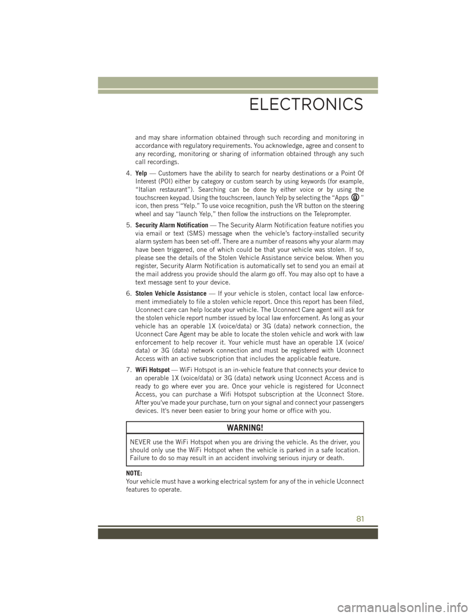
4. Yelp —
Customers have the ability to search for nearby destinations or a Point Of
Interest (POI) either by category or custom search by using keywords (for example,
“Italian restaurant”). Searching can be done by either voice or by using the
touchscreen keypad. Using the touchscreen, launch Yelp by selecting the “Apps
”
icon, then press “Yelp.” To use voice recognition, push the VR button on the steering
wheel and say “launch Yelp,” then follow the instructions on the Teleprompter.
5. Security Alarm Notification — The Security Alarm Notification feature notifies you
via email or text (SMS) message when the vehicle’s factory-installed security
alarm system has been set-off. There are a number of reasons why your alarm may
have been triggered, one of which could be that your vehicle was stolen. If so,
please see the details of the Stolen Vehicle Assistance service below. When you
register, Security Alarm Notification is automatically set to send you an email at
the mail address you provide should the alarm go off. You may also opt to have a
text message sent to your device.
6. Stolen Vehicle Assistance — If your vehicle is stolen, contact local law enforce-
ment immediately to file a stolen vehicle report. Once this report has been filed,
Uconnect care can help locate your vehicle. The Uconnect Care agent will ask for
the stolen vehicle report number issued by local law enforcement. As long as your
vehicle has an operable 1X (voice/data) or 3G (data) network connection, the
Uconnect Care Agent may be able to locate the stolen vehicle and work with law
enforcement to help recover it. Your vehicle must have an operable 1X (voice/
data) or 3G (data) network connection and must be registered with Uconnect
Access with an active subscription that includes the applicable feature.
7. WiFi Hotspot — WiFi Hotspot is an in-vehicle feature that connects your device to
an operable 1X (voice/data) or 3G (data) network using Uconnect Access and is
ready to go where ever you are. Once your vehicle is registered for Uconnect
Access, you can purchase a Wifi Hotspot subscription at the Uconnect Store.
After you've made your purchase, turn on your signal and connect your passengers
devices. It's never been easier to bring your home or office with you.
WARNING!
NEVER use the WiFi Hotspot when you are driving the vehicle. As the driver, you
should only use the WiFi Hotspot when the vehicle is parked in a safe location.
Failure to do so may result in an accident involving serious injury or death.
NOTE:
Your vehicle must have a working electrical system for any of the in vehicle Uconnect
features to operate.
ELECTRONICS
81
Page 146 of 236

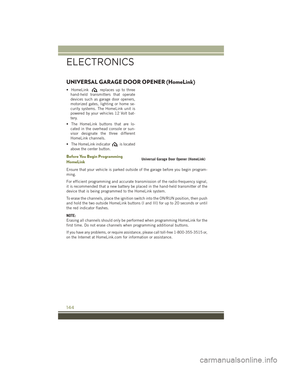
UNIVERSAL GARAGE DOOR OPENER (HomeLink)
• HomeLinkreplaces up to three
hand-held transmitters that operate
devices such as garage door openers,
motorized gates, lighting or home se-
curity systems. The HomeLink unit is
powered by your vehicles 12 Volt bat-
tery.
• The HomeLink buttons that are lo- cated in the overhead console or sun-
visor designate the three different
HomeLink channels.
•
The HomeLink indicatoris located
above the center button.
Before You Begin Programming
HomeLink
Ensure that your vehicle is parked outside of the garage before you begin program-
ming.
For efficient programming and accurate transmission of the radio-frequency signal,
it is recommended that a new battery be placed in the hand-held transmitter of the
device that is being programmed to the HomeLink system.
To erase the channels, place the ignition switch into the ON/RUN position, then push
and hold the two outside HomeLink buttons (I and III) for up to 20 seconds or until
the red indicator flashes.
NOTE:
Erasing all channels should only be performed when programming HomeLink for the
first time. Do not erase channels when programming additional buttons.
If you have any problems, or require assistance, please call toll-free 1-800-355-3515 or,
on the Internet at
HomeLink.com for information or assistance.
Universal Garage Door Opener (HomeLink)
ELECTRONICS
144
Page 178 of 236

4. Remove the cap from the valve stem and then screw the fitting at the end of theSealant Hose (6) onto the valve stem.
5.
Uncoil the Power Plug (8) and insert the plug into the vehicle’s 12 Volt power outlet.
6. Do not remove foreign objects (e.g., screws or nails) from the tire.
(C) Injecting Tire Service Kit Sealant Into The Deflated Tire:
Always start the engine before turning ON the Tire Service Kit.
NOTE:
Manual transmission vehicles must have the parking brake engaged and the shift
lever in NEUTRAL.
After pushing the Power Button (4), the sealant (white fluid) will flow from the
Sealant Bottle (1) through the Sealant Hose (6) and into the tire.
NOTE:
Sealant may leak out through the puncture in the tire.
If the sealant (white fluid) does not flow withi n0–10seconds through the Sealant Hose (6):
1. Push the Power Button (4) to turn Off the Tire Service Kit. Disconnect the Sealant
Hose (6) from the valve stem. Make sure the valve stem is free of debris.
Reconnect the Sealant Hose (6) to the valve stem. Check that the Mode Select
Knob (5) is in the Sealant Mode position and not Air Mode. Push the Power Button
(4) to turn On the Tire Service Kit.
2. Connect the Power Plug (8) to a different 12 Volt power outlet in your vehicle or another vehicle, if available. Make sure the engine is running before turning ON
the Tire Service Kit.
3. The Sealant Bottle (1) may be empty due to previous use. Call for assistance.
NOTE:
If the Mode Select Knob (5) is on Air Mode and the pump is operating, air will
dispense from the Air Pump Hose (7) only, not the Sealant Hose (6).
If the sealant (white fluid) does flow through the Sealant Hose (6):
1. Continue to operate the pump until sealant is no longer flowing through the hose (typically takes 30 - 70 seconds). As the sealant flows through the Sealant Hose
(6), the Pressure Gauge (3) can read as high as 70 psi (4.8 Bar). The Pressure
Gauge (3) will decrease quickly from approximately 70 psi (4.8 Bar) to the actual
tire pressure when the Sealant Bottle (1) is empty.
2. The pump will start to inject air into the tire immediately after the Sealant Bottle (1) is empty. Continue to operate the pump and inflate the tire to the pressure
indicated on the tire pressure label on the driver-side latch pillar (recommended
pressure). Check the tire pressure by looking at the Pressure Gauge (3).
WHAT TO DO IN EMERGENCIES
176
Page 209 of 236

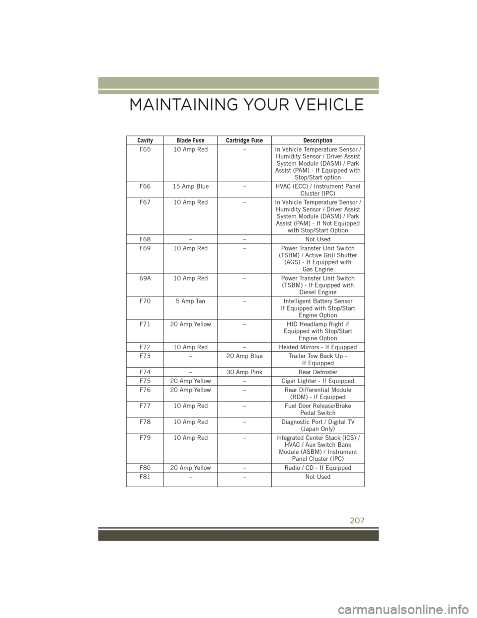
Cavity Blade Fuse Cartridge FuseDescription
F65 10 Amp Red – In Vehicle Temperature Sensor /
Humidity Sensor / Driver AssistSystem Module (DASM) / Park
Assist (PAM) - If Equipped with Stop/Start option
F66 15 Amp Blue – HVAC (ECC) / Instrument Panel
Cluster (IPC)
F67 10 Amp Red – In Vehicle Temperature Sensor /
Humidity Sensor / Driver AssistSystem Module (DASM) / Park
Assist (PAM) - If Not Equipped with Stop/Start Option
F68 – – Not Used
F69 10 Amp Red –Power Transfer Unit Switch
(TSBM) / Active Grill Shutter (AGS) - If Equipped with Gas Engine
69A 10 Amp Red –Power Transfer Unit Switch
(TSBM) - If Equipped with Diesel Engine
F70 5 Amp Tan –Intelligent Battery Sensor
If Equipped with Stop/Start Engine Option
F71 20 Amp Yellow –HID Headlamp Right if
Equipped with Stop/Start Engine Option
F72 10 Amp Red –Heated Mirrors - If Equipped
F73 –20 Amp Blue Trailer Tow Back Up -
If Equipped
F74 –30 Amp Pink Rear Defroster
F75 20 Amp Yellow –Cigar Lighter - If Equipped
F76 20 Amp Yellow –Rear Differential Module
(RDM) - If Equipped
F77 10 Amp Red –Fuel Door Release/Brake
Pedal Switch
F78 10 Amp Red –Diagnostic Port / Digital TV
(Japan Only)
F79 10 Amp Red – Integrated Center Stack (ICS) /
HVAC / Aux Switch Bank
Module (ASBM) / Instrument Panel Cluster (IPC)
F80 20 Amp Yellow –Radio / CD - If Equipped
F81 – – Not Used
MAINTAINING YOUR VEHICLE
207