2016 HYUNDAI TUCSON sensor
[x] Cancel search: sensorPage 452 of 642
5-68
Driving your vehicle
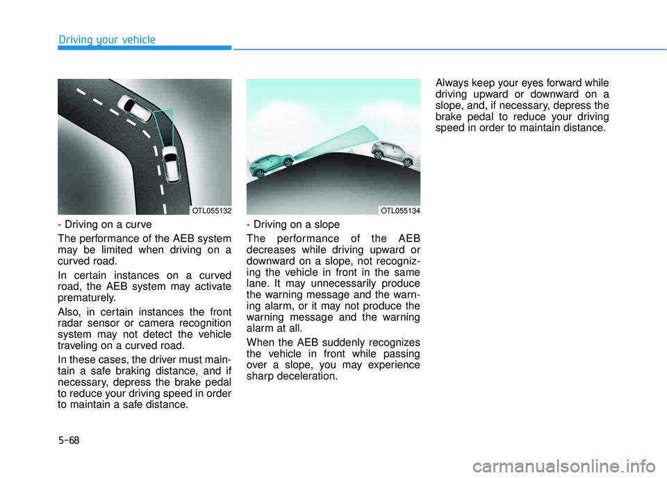
- Driving on a curve
The performance of the AEB system
may be limited when driving on a
curved road.
In certain instances on a curved
road, the AEB system may activate
prematurely.
Also, in certain instances the front
radar sensor or camera recognition
system may not detect the vehicle
traveling on a curved road.
In these cases, the driver must main-
tain a safe braking distance, and if
necessary, depress the brake pedal
to reduce your driving speed in order
to maintain a safe distance.- Driving on a slope
The performance of the AEB
decreases while driving upward or
downward on a slope, not recogniz-
ing the vehicle in front in the same
lane. It may unnecessarily produce
the warning message and the warn-
ing alarm, or it may not produce the
warning message and the warning
alarm at all.
When the AEB suddenly recognizes
the vehicle in front while passing
over a slope, you may experience
sharp deceleration.Always keep your eyes forward while
driving upward or downward on a
slope, and, if necessary, depress the
brake pedal to reduce your driving
speed in order to maintain distance.
OTL055134OTL055132
Page 454 of 642
5-70
Driving your vehicle
Detecting pedestrians
The sensor may be limited when:
- The pedestrian is not fully detectedby the camera recognition system,
for example, if the pedestrian is
leaning over or is not fully walking
upright
- The pedestrian is moving very quickly or appears abruptly in the
camera detection area
The pedestrian is wearing clothing
that easily blends into the back-
ground, making it difficult to be
detected by the camera recogni-tion system
- The outside lighting is too bright (e.g. when driving in bright sunlight
or in sun glare) or too dark (e.g.
when driving on a dark rural roadat night)
- It is difficult to detect and distin- guish the pedestrian from other
objects in the surroundings, for
example, when there is a group of
pedestrians or a large crowdInformation
In some instances, the AEB system
may be cancelled when subjected to
electromagnetic interference.
Information
This device complies with Part 15 of
the FCC rules.
Operation is subject to the following
two conditions:
1. This device may not cause harmful interference, and
2. This device must accept any inter- ference received, including interfer-
ence that may cause undesired
operation.
i
i
Do not use the Autonomous
Emergency Braking system
when towing a vehicle.Application of the AEB system
while towing may adversely
affect the safety of your vehi-
cle or the towing vehicle
Use extreme caution when the
vehicle in front of you has
cargo that extends rearward
from the cab, or when the
vehicle in front of you has
higher ground clearance.
The AEB system is designed to detect and monitor the vehi-
cle ahead or detect a pedestri-
an in the roadway throughradar signals and camera
recognition. It is not designed
to detect bicycles, motorcy-
cles, or smaller wheeled
objects such as luggage bags,
shopping carts, or strollers.
Never try to test the operation
of the AEB system. Doing so
may cause severe injury ordeath.
WARNING
Page 498 of 642

6-11
What to do in an emergency
6
If any of the below happens, have
the system checked by an author-
ized HYUNDAI dealer.
1. The Low Tire Pressure TPMSMalfunction Indicator does not
illuminate for 3 seconds when
the ignition switch is placed tothe ON position or engine isrunning.
2. The TPMS Malfunction Indicator remains illuminated after blink-
ing for approximately 1 minute.
3. The Low Tire Pressure LCD dis- play remains illuminated
Low tire pressure indicator
Low tire pressure LCD displaywith position indicator
When the tire pressure monitoring
system warning indicators are illumi-
nated and the warning message is
displayed on the cluster LCD display,
one or more of your tires is signifi-
cantly under-inflated. The LCD posi-tion indicator will indicate which tire
is significantly under-inflated by illu-minating the corresponding positionlight. If any of your tire pressures are indi-
cated as being low, immediately
reduce your speed, avoid hard cor-
nering, and anticipate increased
stopping distances. You should stop
and check your tires as soon as pos-
sible. Inflate the tires to the proper
pressure as indicated on the vehi-
cle’s placard or tire inflation pressure
label located on the driver’s side cen-ter pillar outer panel.
If you cannot reach a service station
or if the tire cannot hold the newly
added air, replace the low pressure
tire with the spare tire.
The Low Tire Pressure LCD position indicator will remain on and the
TPMS Malfunction Indicator may
blink for one minute and then remain
illuminated until you have the lowpressure tire repaired and replaced
on the vehicle. The spare tire is not equipped with
a tire pressure sensor.
NOTICE
NOTICE
OTL045154L
Page 500 of 642
6-13
What to do in an emergency
6
The TPMS Malfunction Indicator
may illuminate after blinking for
one minute if the vehicle is near
electric power supply cables or
radio transmitters such as police
stations, government and public
offices, broadcasting stations,
military installations, airports,
transmitting towers, etc.
Additionally, the TPMS Malfunction
Indicator may illuminate if snow
chains are used or electronic
devices such as computers, charg-
ers, remote starters, navigation,
etc. This may interfere with normal
operation of the TPMS.
Changing a Tire with TPMS
If you have a flat tire, the Low Tire Pressure and LCD position indicator
will come on. Have the flat tire
repaired by an authorized HYUNDAI
dealer as soon as possible orreplace the flat tire with the spare
tire. The spare tire does not come with a
tire pressure monitoring sensor.
When the low pressure tire or the flat
tire is replaced with the spare tire,
the Low Tire Pressure LCD position
indicator will remain on. Also, theTPMS Malfunction Indicator will illu-
minate after blinking for one minute if
the vehicle is driven at speed above
15.5 mph (25 km/h) for approximate-
ly 20 minutes.Once the original tire equipped with
a tire pressure monitoring sensor isreinflated to the recommended pres-
sure and reinstalled on the vehicle,
the Low Tire Pressure LCD position
indicator and TPMS Malfunction
Indicator will go off within a few min-
utes of driving. If the indicators do not disappear
after a few minutes, please visit an
authorized HYUNDAI dealer. Each wheel is equipped with a tire pressure sensor mounted inside the
tire behind the valve stem (except for
the spare tire). You must use TPMS
specific wheels. It is recommended
that you always have your tires serv-
iced by an authorized HYUNDAI
dealer.
NOTICE
Never use a puncture-repairing
agent not approved by HYUNDAIdealer to repair and/or inflate a
low pressure tire. Tire sealant
not approved by HYUNDAI deal-
er may damage the tire pressure
sensor.
CAUTION
Page 511 of 642
6-24
When towing your vehicle in an emergency without wheel dollies:
1.Place the ignition switch in theACC position.
2.Place the shift lever in N (Neutral).
3.Release the parking brake.
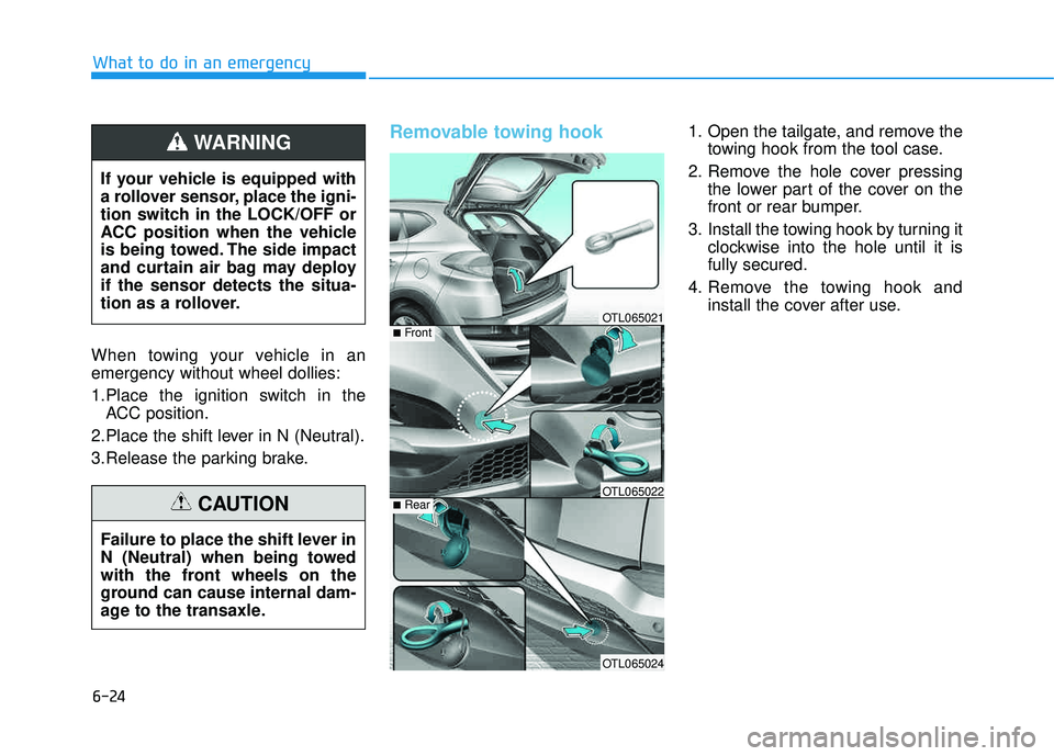
Removable towing hook 1. Open the tailgate, and remove the towing hook from the tool case.
2. Remove the hole cover pressing the lower part of the cover on the
front or rear bumper.
3. Install the towing hook by turning it clockwise into the hole until it isfully secured.
4. Remove the towing hook and install the cover after use.
What to do in an emergency
If your vehicle is equipped with
a rollover sensor, place the igni-
tion switch in the LOCK/OFF or
ACC position when the vehicle
is being towed. The side impact
and curtain air bag may deployif the sensor detects the situa-
tion as a rollover.
WARNING
Failure to place the shift lever in
N (Neutral) when being towed
with the front wheels on the
ground can cause internal dam-
age to the transaxle.
CAUTION
OTL065021
OTL065022
OTL065024
■Front
■Rear
Page 552 of 642
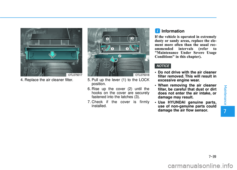
7-39
7
Maintenance
4. Replace the air cleaner filter. 5. Pull up the lever (1) to the LOCKposition.
6. Rise up the cover (2) until the hooks on the cover are securely
fastened into the latches (3).
7. Check if the cover is firmly installed.
Information
If the vehicle is operated in extremely
dusty or sandy areas, replace the ele-
ment more often than the usual rec-
ommended intervals (refer to
"Maintenance Under Severe Usage
Conditions" in this chapter).
Do not drive with the air cleanerfilter removed. This will result in
excessive engine wear.
When removing the air cleaner filter, be careful that dust or dirt
does not enter the air intake, or
damage may result.
Use HYUNDAI genuine parts, use of non-genuine parts could
damage the air flow sensor.
NOTICE
i
OTL075017OTL075018
Page 583 of 642
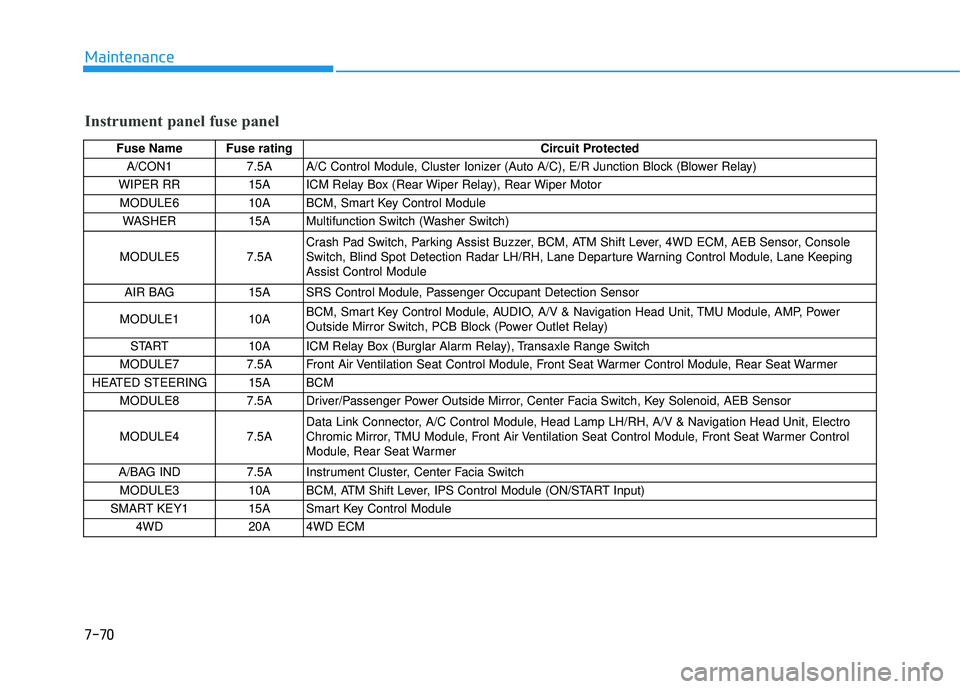
7-70
Maintenance
Instrument panel fuse panel
Fuse Name Fuse ratingCircuit Protected
A/CON1 7.5A A/C Control Module, Cluster Ionizer (Auto A/C), E/R Junction Block (Blower Relay)
WIPER RR 15A ICM Relay Box (Rear Wiper Relay), Rear Wiper Motor MODULE6 10A BCM, Smart Key Control Module WASHER 15A Multifunction Switch (Washer Switch)
MODULE5 7.5A Crash Pad Switch, Parking Assist Buzzer, BCM, ATM Shift Lever, 4WD ECM, AEB Sensor, Console
Switch, Blind Spot Detection Radar LH/RH, Lane Departure Warning Control Module, Lane KeepingAssist Control Module
AIR BAG 15A SRS Control Module, Passenger Occupant Detection Sensor
MODULE1 10A BCM, Smart Key Control Module, AUDIO, A/V & Navigation Head Unit, TMU Module, AMP, Power
Outside Mirror Switch, PCB Block (Power Outlet Relay)
START 10A ICM Relay Box (Burglar Alarm Relay), Transaxle Range Switch
MODULE7 7.5A Front Air Ventilation Seat Control Module, Front Seat Warmer Control Module, Rear Seat Warmer
HEATED STEERING 15A BCM MODULE8 7.5A Driver/Passenger Power Outside Mirror, Center Facia Switch, Key Solenoid, AEB Sensor MODULE4 7.5A Data Link Connector, A/C Control Module, Head Lamp LH/RH, A/V & Navigation Head Unit, Electro
Chromic Mirror, TMU Module, Front Air Ventilation Seat Control Module, Front Seat Warmer Control
Module, Rear Seat Warmer
A/BAG IND 7.5A Instrument Cluster, Center Facia Switch MODULE3 10A BCM, ATM Shift Lever, IPS Control Module (ON/START Input)
SMART KEY1 15A Smart Key Control Module 4WD 20A 4WD ECM
Page 584 of 642
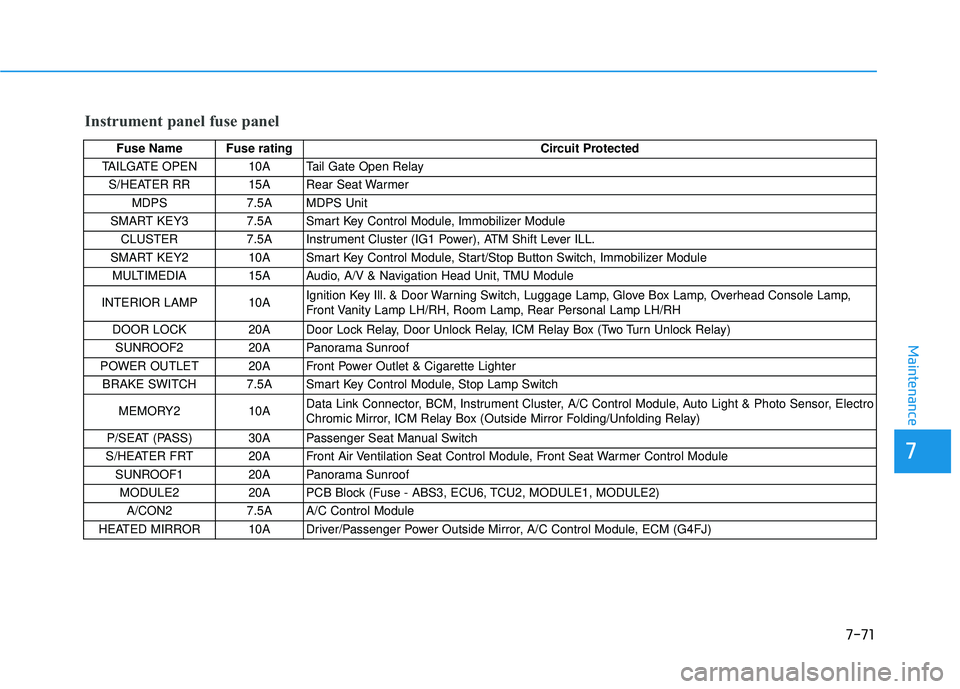
7-71
7
Maintenance
Instrument panel fuse panel
Fuse Name Fuse ratingCircuit Protected
TAILGATE OPEN 10A Tail Gate Open Relay
S/HEATER RR 15A Rear Seat Warmer MDPS 7.5A MDPS Unit
SMART KEY3 7.5A Smart Key Control Module, Immobilizer Module
CLUSTER 7.5A Instrument Cluster (IG1 Power), ATM Shift Lever ILL.
SMART KEY2 10A Smart Key Control Module, Start/Stop Button Switch, Immobilizer Module MULTIMEDIA 15A Audio, A/V & Navigation Head Unit, TMU Module
INTERIOR LAMP 10A Ignition Key Ill. & Door Warning Switch, Luggage Lamp, Glove Box Lamp, Overhead Console Lamp,
Front Vanity Lamp LH/RH, Room Lamp, Rear Personal Lamp LH/RH
DOOR LOCK 20A Door Lock Relay, Door Unlock Relay, ICM Relay Box (Two Turn Unlock Relay) SUNROOF2 20A Panorama Sunroof
POWER OUTLET 20A Front Power Outlet & Cigarette Lighter BRAKE SWITCH 7.5A Smart Key Control Module, Stop Lamp Switch
MEMORY2 10A Data Link Connector, BCM, Instrument Cluster, A/C Control Module, Auto Light & Photo Sensor, Electro
Chromic Mirror, ICM Relay Box (Outside Mirror Folding/Unfolding Relay)
P/SEAT (PASS) 30A Passenger Seat Manual Switch
S/HEATER FRT 20A Front Air Ventilation Seat Control Module, Front Seat Warmer Control Module
SUNROOF1 20A Panorama Sunroof
MODULE2 20A PCB Block (Fuse - ABS3, ECU6, TCU2, MODULE1, MODULE2) A/CON2 7.5A A/C Control Module
HEATED MIRROR 10A Driver/Passenger Power Outside Mirror, A/C Control Module, ECM (G4FJ)