Page 207 of 642
3-109
Convenient features of your vehicle
3
High beam operation
To turn on the high beam headlamp,
push the lever away from you. The
lever will return to its original position. The high beam indicator will light when the headlamp high beams are
switched on.
To turn off the high beam headlamp,
pull the lever towards you. The low
beams will turn on.To flash the high beam headlamp,
pull the lever towards you, then
release the lever. The high beams
will remain ON as long as you hold
the lever towards you.
OTLA045254
Do not use high beam when there
are other vehicles approaching
you. Using high beam could
obstruct the other driver’s vision.
WARNING
OTLA045255
Page 217 of 642

3-119
Convenient features of your vehicle
3
Windshield Washers
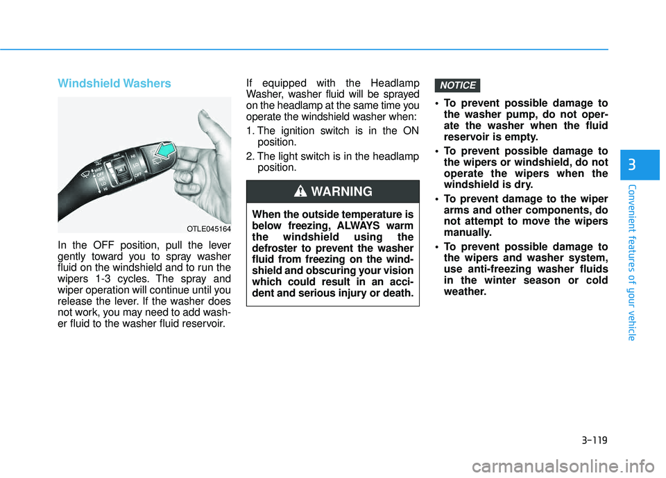
In the OFF position, pull the lever
gently toward you to spray washer
fluid on the windshield and to run the
wipers 1-3 cycles. The spray and
wiper operation will continue until you
release the lever. If the washer does
not work, you may need to add wash-
er fluid to the washer fluid reservoir.If equipped with the Headlamp
Washer, washer fluid will be sprayed
on the headlamp at the same time you
operate the windshield washer when:
1. The ignition switch is in the ON
position.
2. The light switch is in the headlamp position. To prevent possible damage to
the washer pump, do not oper- ate the washer when the fluid
reservoir is empty.
To prevent possible damage to the wipers or windshield, do not
operate the wipers when the
windshield is dry.
To prevent damage to the wiper arms and other components, do
not attempt to move the wipers
manually.
To prevent possible damage to the wipers and washer system,use anti-freezing washer fluidsin the winter season or cold
weather.
NOTICE
When the outside temperature is
below freezing, ALWAYS warmthe windshield using the
defroster to prevent the washer
fluid from freezing on the wind-
shield and obscuring your vision
which could result in an acci-
dent and serious injury or death.
WARNING
OTLE045164
Page 227 of 642

3-129
Convenient features of your vehicle
3
Mode selection
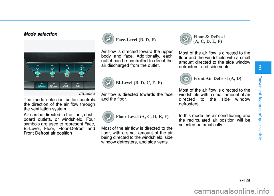
The mode selection button controls
the direction of the air flow through
the ventilation system.
Air can be directed to the floor, dash-
board outlets, or windshield. Four
symbols are used to represent Face,
Bi-Level, Floor, Floor-Defrost and
Front Defrost air position
Face-Level (B, D, F)
Air flow is directed toward the upper
body and face. Additionally, eachoutlet can be controlled to direct theair discharged from the outlet.
Bi-Level (B, D, C, E, F)
Air flow is directed towards the face
and the floor.
Floor-Level (A, C, D, E, F)
Most of the air flow is directed to the
floor, with a small amount of the airbeing directed to the windshield, side
window defrosters, and side vents.
Floor & Defrost
(A, C, D, E, F)
Most of the air flow is directed to the floor and the windshield with a small
amount directed to the side window
defrosters, and side vents.
Front Air Defrost (A, D)
Most of the air flow is directed to the windshield with a small amount of air
directed to the side window
defrosters. In this mode the air conditioning and the recirculated air position will be
selected automatically.OTL045208
Page 228 of 642
3-130
Convenient features of your vehicle
MAX A/C-Level (B, D)
The MAX A/C mode is used to cool
the inside of the vehicle faster. Air
flow is directed toward the upper
body and face.
In this mode, the air conditioning and the recirculated air position will be
selected automatically.
Instrument panel vents
The outlet vents can be opened ( )
or closed ( ) separately using the thumbwheel.
Also, you can adjust the direction of
air delivered from these vents using
the vent control lever as shown.
Temperature control
The temperature will increase by
turning the knob to the right.
The temperature will decrease by
turning the knob to the left.
OTL045209OTL045086OTL045210
Page 239 of 642
3-141
Convenient features of your vehicle
3
The air flow outlet direction is cycled
as follows:
Face-Level (B, D, F)
Air flow is directed toward the upper
body and face. Additionally, eachoutlet can be controlled to direct theair discharged from the outlet.
Bi-Level (B, C, D, E, F)
Air flow is directed towards the face
and the floor.
Floor & Defrost
(A, C, D, E, F)
Most of the air flow is directed to the floor and the windshield with a small
amount directed to the side window
defrosters.
Floor-Level (A, C, D, E, F)
Most of the air flow is directed to the
floor, with a small amount of the airbeing directed to the windshield and
side window defrosters.
Defrost-Level (A)
Most of the air flow is directed to the windshield with a small amount of air
directed to the side window defrosters.
OTLE045263R
■Type B OTLE045218R
■
Type A
Page 260 of 642
3-162
Convenient features of your vehicle
To use the cargo security screen
1. Pull the cargo security screentowards the rear of the vehicle by the handle (1).
2. Pull the cargo screen out all the way and then slowly allow the
screen to retract back into themechanism.
When the cargo security screen is
not in use:
1. Pull the cargo security screenbackward and up to release it from
the guides.
2. The cargo security screen will automatically slide back in.
The cargo security screen may
not automatically slide back in if
the cargo security screen is not
fully pulled out. Pull the cargo
screen out all the way and then
slowly allow the screen to retract
back into the mechanism.
To remove the cargo security screen
1. Push one side of the cargo screen inward to compress the springmechanism and release the
screen from the vehicle.
2. While the mechanism is com- pressed, pull out the cargo securi-ty screen.
NOTICE
OTLA045323
OTLA045324
Page 268 of 642

4-5
Multimedia System
4
How Vehicle Audio Works
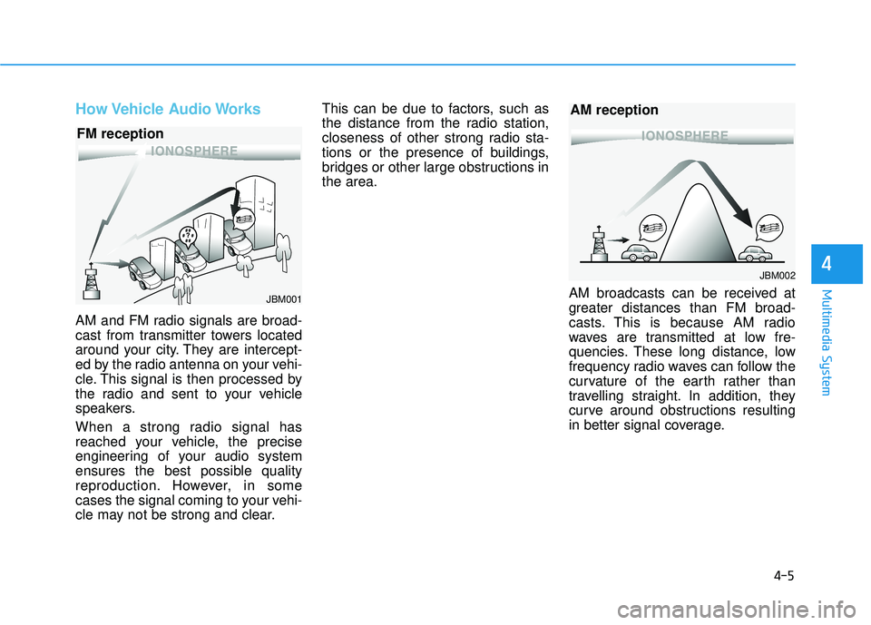
AM and FM radio signals are broad-
cast from transmitter towers located
around your city. They are intercept-
ed by the radio antenna on your vehi-
cle. This signal is then processed by
the radio and sent to your vehicle
speakers.
When a strong radio signal has
reached your vehicle, the precise
engineering of your audio system
ensures the best possible quality
reproduction. However, in some
cases the signal coming to your vehi-
cle may not be strong and clear.This can be due to factors, such as
the distance from the radio station,
closeness of other strong radio sta-
tions or the presence of buildings,
bridges or other large obstructions inthe area.
AM broadcasts can be received at
greater distances than FM broad-
casts. This is because AM radio
waves are transmitted at low fre-
quencies. These long distance, low
frequency radio waves can follow the
curvature of the earth rather than
travelling straight. In addition, they
curve around obstructions resulting
in better signal coverage.
JBM001
FM reception
JBM002
AM reception
Page 386 of 642

5
Special driving conditions ...................................5-80
Hazardous driving conditions.......................................5-80
Rocking the vehicle ........................................................5-80
Smooth cornering ...........................................................5-81
Driving at night ................................................................5-81
Driving in the rain ...........................................................5-82
Driving in flooded areas ................................................5-82
Highway driving ...............................................................5-83
Reducing the risk of a rollover ...................................5-83
Winter driving .......................................................5-85
Snow or Icy Conditions ..................................................5-85
Winter Precautions .........................................................5-87
Trailer towing .......................................................5-89
If you decide to pull a trailer? .....................................5-90
Trailer towing equipment ..............................................5-92
Driving with a trailer ......................................................5-93
Maintenance when trailer towing ...............................5-97
Vehicle load limit ..................................................5-98
Tire Loading Information Label ...................................5-99