Page 658 of 699
761
Maintenance
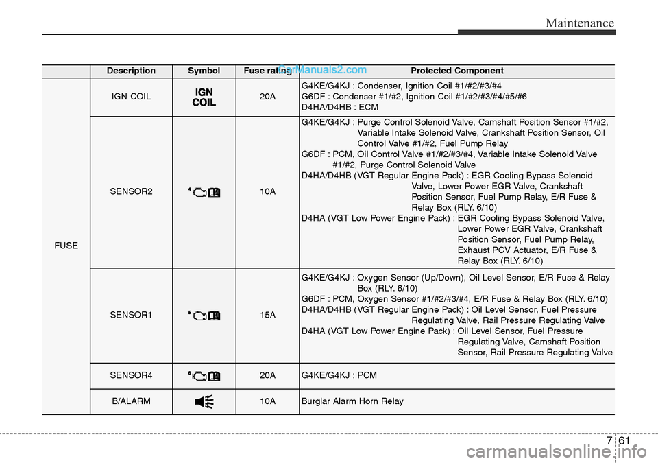
DescriptionSymbol Fuse ratingProtected Component
FUSE
IGN COIL20AG4KE/G4KJ : Condenser, Ignition Coil #1/#2/#3/#4
G6DF : Condenser #1/#2, Ignition Coil #1/#2/#3/#4/#5/#6
D4HA/D4HB : ECM
SENSOR210A
G4KE/G4KJ : Purge Control Solenoid Valve, Camshaft Position Sensor #1/#2,
Variable Intake Solenoid Valve, Crankshaft Position Sensor, Oil
Control Valve #1/#2, Fuel Pump Relay
G6DF : PCM, Oil Control Valve #1/#2/#3/#4, Variable Intake Solenoid Valve
#1/#2, Purge Control Solenoid Valve
D4HA/D4HB (VGT Regular Engine Pack) : EGR Cooling Bypass Solenoid
Valve, Lower Power EGR Valve, Crankshaft
Position Sensor, Fuel Pump Relay, E/R Fuse &
Relay Box (RLY. 6/10)
D4HA (VGT Low Power Engine Pack) : EGR Cooling Bypass Solenoid Valve,
Lower Power EGR Valve, Crankshaft
Position Sensor, Fuel Pump Relay,
Exhaust PCV Actuator, E/R Fuse &
Relay Box (RLY. 6/10)
SENSOR115A
G4KE/G4KJ : Oxygen Sensor (Up/Down), Oil Level Sensor, E/R Fuse & Relay
Box (RLY. 6/10)
G6DF : PCM, Oxygen Sensor #1/#2/#3/#4, E/R Fuse & Relay Box (RLY. 6/10)
D4HA/D4HB (VGT Regular Engine Pack) : Oil Level Sensor, Fuel Pressure
Regulating Valve, Rail Pressure Regulating Valve
D4HA (VGT Low Power Engine Pack) : Oil Level Sensor, Fuel Pressure
Regulating Valve, Camshaft Position
Sensor, Rail Pressure Regulating Valve
SENSOR420AG4KE/G4KJ : PCM
B/ALARM10ABurglar Alarm Horn Relay
Page 659 of 699
Maintenance
62 7
Engine compartment fuse panel
(Diesel engine only)
ODM072049
ODM074045
Page 666 of 699
769
Maintenance
Headlight and front fog light
aiming (for Europe)
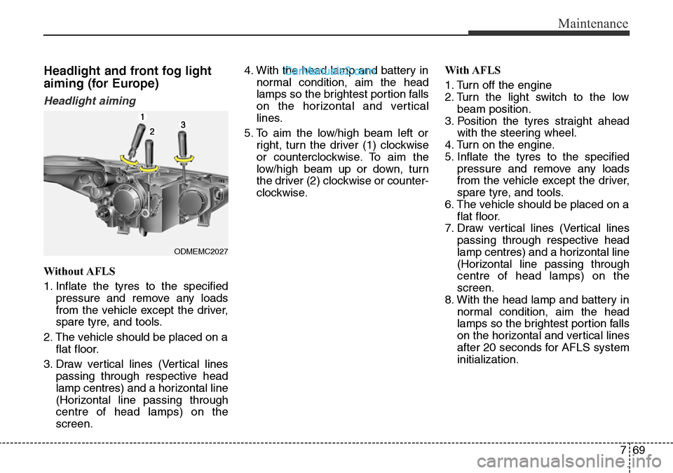
Headlight aiming
Without AFLS
1. Inflate the tyres to the specified
pressure and remove any loads
from the vehicle except the driver,
spare tyre, and tools.
2. The vehicle should be placed on a
flat floor.
3. Draw vertical lines (Vertical lines
passing through respective head
lamp centres) and a horizontal line
(Horizontal line passing through
centre of head lamps) on the
screen.4. With the head lamp and battery in
normal condition, aim the head
lamps so the brightest portion falls
on the horizontal and vertical
lines.
5. To aim the low/high beam left or
right, turn the driver (1) clockwise
or counterclockwise. To aim the
low/high beam up or down, turn
the driver (2) clockwise or counter-
clockwise.With AFLS
1. Turn off the engine
2. Turn the light switch to the low
beam position.
3. Position the tyres straight ahead
with the steering wheel.
4. Turn on the engine.
5. Inflate the tyres to the specified
pressure and remove any loads
from the vehicle except the driver,
spare tyre, and tools.
6. The vehicle should be placed on a
flat floor.
7. Draw vertical lines (Vertical lines
passing through respective head
lamp centres) and a horizontal line
(Horizontal line passing through
centre of head lamps) on the
screen.
8. With the head lamp and battery in
normal condition, aim the head
lamps so the brightest portion falls
on the horizontal and vertical lines
after 20 seconds for AFLS system
initialization.
ODMEMC2027
Page 671 of 699
Maintenance
74 7
Side repeater lamp replace-
ment
If the light bulb does not operate, we
recommend that the system be
checked by a HYUNDAI authorised
repairer.
Rear combination lamp bulb
replacement
(1) Stop/tail lamp
(2) Tail lamp
(3) Rear turn signal lamp
(4) Back-up lamp
Outside lamp
Rear turn signal lamp and stop/tail
lamp
1. Turn off the engine.
2. Open the tailgate.
3. Loosen the lamp assembly retain-
ing screws with a cross-tip screw-
driver.
4. Remove the rear combination
lamp assembly from the body of
the vehicle.
ODM072033
ODMEMC2007
■Type A
■Type BODM072034
ODM072031/H
Page 672 of 699
775
Maintenance
5. Remove the socket from the
assembly by turning the socket
counterclockwise until the tabs on
the socket align with the slots on
the assembly.6. Remove the bulb from the socket
by pressing it in and rotating it
counterclockwise until the tabs on
the bulb align with the slots in the
socket. Pull the bulb out of the
socket.
7. Insert a new bulb by inserting it
into the socket and rotating it until
it locks into place.
8. Install the socket in the assembly
by aligning the tabs on the socket
with the slots in the assembly.
Push the socket into the assembly
and turn the socket clockwise.
9. Reinstall the lamp assembly to the
body of the vehicle.
Inside lamp
1. Turn off the engine.
2. Open the tailgate.
3. Remove the service cover using a
flat-blade screwdriver.
ODM072036
ODM072035
ODMEMC2010 ■Type A
■Type B
Page 678 of 699
781
Maintenance
Waxing
Wax the vehicle when water will no
longer bead on the paint.
Always wash and dry the vehicle
before waxing. Use a good quality
liquid or paste wax, and follow the
manufacturer’s instructions. Wax all
metal trim to protect it and to main-
tain its luster. Removing oil, tar, and
similar materials with a spot remover
will usually strip the wax from the fin-
ish. Be sure to re-wax these areas
even if the rest of the vehicle does
not yet need waxing.Finish damage repair
Deep scratches or stone chips in the
painted surface must be repaired
promptly. Exposed metal will quickly
rust and may develop into a major
repair expense.
✽NOTICE
If your vehicle is damaged and
requires any metal repair or
replacement, be sure the body shop
applies anti-corrosion materials to
the parts repaired or replaced.
CAUTION
• Wiping dust or dirt off the
body with a dry cloth will
scratch the finish.
• Do not use steel wool, abra-
sive cleaners, or strong deter-
gents containing highly alka-
line or caustic agents on
chrome-plated or anodized
aluminum parts. This may
result in damage to the pro-
tective coating and cause dis-
colouration or paint deteriora-
tion.
CAUTION
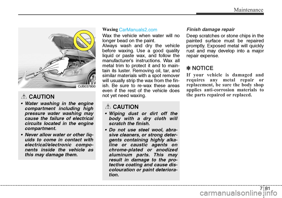
• Water washing in the engine
compartment including high
pressure water washing may
cause the failure of electrical
circuits located in the engine
compartment.
• Never allow water or other liq-
uids to come in contact with
electrical/electronic compo-
nents inside the vehicle as
this may damage them.
OJB037800
Page 684 of 699
787
Maintenance
EMISSION CONTROL SYSTEM
The emission control system of your
vehicle is covered by a written limited
warranty. Please see the warranty
information contained in the
Warranty Booklet in your vehicle.
Your vehicle is equipped with an
emission control system to meet all
emission regulations.
There are three emission control
systems which are as follows.
(1) Crankcase emission control sys-
tem
(2) Evaporative emission control sys-
tem
(3) Exhaust emission control system
In order to assure the proper function
of the emission control systems, it is
recommended that you have your
car inspected and maintained by a
HYUNDAI authorised repairer in
accordance with the maintenance
schedule.Caution for the Inspection and
Maintenance Test (With Electronic
Stability Control (ESC) system)
• To prevent the vehicle from mis-
firing during dynamometer test-
ing, turn the Electronic Stability
Control (ESC) system off by
pressing the ESC switch.
• After dynamometer testing is
completed, turn the ESC system
back on by pressing the ESC
switch again.
1. Crankcase emission control
system
The positive crankcase ventilation
system is employed to prevent air
pollution caused by blow-by gases
being emitted from the crankcase.
This system supplies fresh filtered air
to the crankcase through the air
intake hose. Inside the crankcase,
the fresh air mixes with blow-by
gases, which then pass through the
PCV valve into the induction system.
2. Evaporative emission con-
trol system
The Evaporative Emission Control
System is designed to prevent fuel
vapours from escaping into the
atmosphere.
Canister
Fuel vapours generated inside the
fuel tank are absorbed and stored in
the onboard canister. When the
engine is running, the fuel vapours
absorbed in the canister are drawn
into the surge tank through the purge
control solenoid valve.
Purge Control Solenoid Valve
(PCSV)
The purge control solenoid valve is
controlled by the Engine Control
Module (ECM); when the engine
coolant temperature is low during
idling, the PCSV closes so that evap-
ourated fuel is not taken into the
engine. After the engine warms-up
during ordinary driving, the PCSV
opens to introduce evapourated fuel
to the engine.
Page 685 of 699
Maintenance
88 7
3. Exhaust emission control
system
The Exhaust Emission Control
System is a highly effective system
which controls exhaust emissions
whilst maintaining good vehicle per-
formance.
Vehicle modifications
This vehicle should not be modified.
Modification of your vehicle could
affect its performance, safety or
durability and may even violate gov-
ernmental safety and emissions reg-
ulations.
In addition, damage or performance
problems resulting from any modifi-
cation may not be covered under
warranty.
• If you use unauthorised electronic
devices, it may cause the vehicle to
operate abnormally, wire damage,
battery discharge and fire. For your
safety, do not use unauthorised
electronic devices.
Engine exhaust gas precautions
(carbon monoxide)
• Carbon monoxide can be present
with other exhaust fumes.
Therefore, if you smell exhaust
fumes of any kind inside your vehi-
cle, have it inspected and repaired
immediately. If you ever suspect
exhaust fumes are coming into
your vehicle, drive it only with all
the windows fully open. Have your
vehicle checked and repaired
immediately.• Do not operate the engine in con-
fined or closed areas (such as
garages) any more than what is
necessary to move the vehicle in or
out of the area.
• When the vehicle is stopped in an
open area for more than a short
time with the engine running,
adjust the ventilation system (as
needed) to draw outside air into the
vehicle.
• Never sit in a parked or stopped
vehicle for any extended time with
the engine running.
• When the engine stalls or fails to
start, excessive attempts to restart
the engine may cause damage to
the emission control system.
WARNING - Exhaust
Engine exhaust gases contain
carbon monoxide (CO). Though
colourless and odourless, it is
dangerous and could be lethal if
inhaled. Follow the instructions
following to avoid CO poison-
ing.