2016 HYUNDAI IX35 engine
[x] Cancel search: enginePage 162 of 550

477
Features of your vehicle
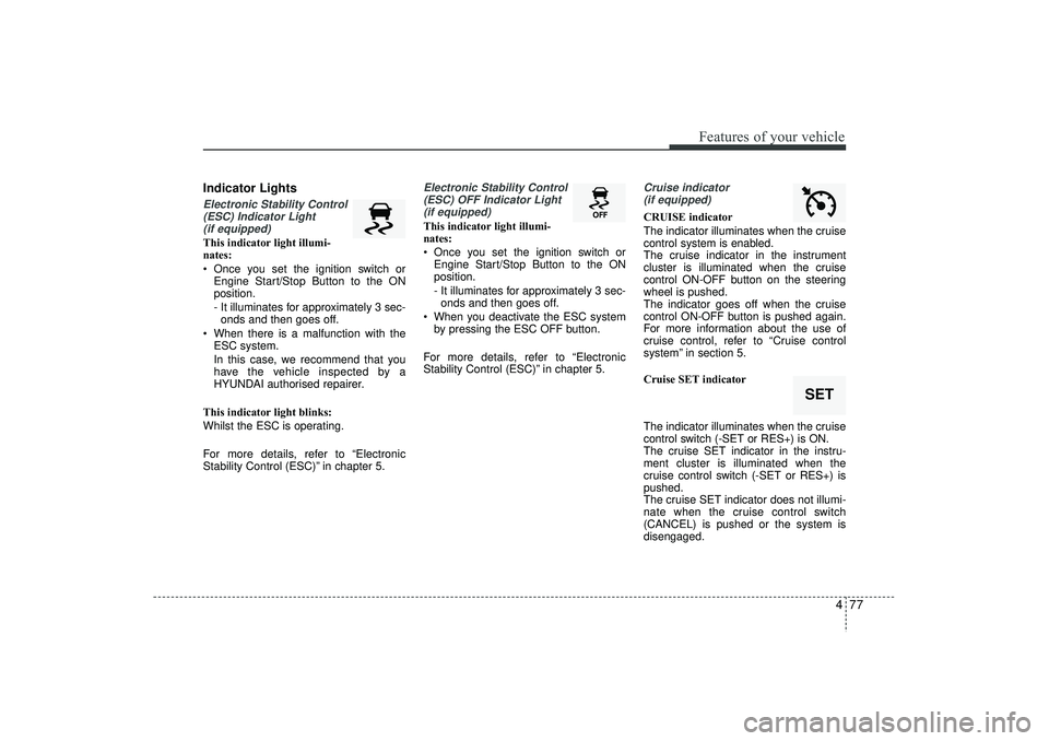
Indicator LightsElectronic Stability Control(ESC) Indicator Light (if equipped)This indicator light illumi-
nates:
Once you set the ignition switch or Engine Start/Stop Button to the ON
position.
- It illuminates for approximately 3 sec-onds and then goes off.
When there is a malfunction with the ESC system.
In this case, we recommend that you
have the vehicle inspected by a
HYUNDAI authorised repairer.
This indicator light blinks:
Whilst the ESC is operating.
For more details, refer to “Electronic
Stability Control (ESC)” in chapter 5.
Electronic Stability Control (ESC) OFF Indicator Light (if equipped)This indicator light illumi-
nates:
Once you set the ignition switch or Engine Start/Stop Button to the ON
position.
- It illuminates for approximately 3 sec-onds and then goes off.
When you deactivate the ESC system by pressing the ESC OFF button.
For more details, refer to “Electronic
Stability Control (ESC)” in chapter 5.
Cruise indicator (if equipped)CRUISE indicator
The indicator illuminates when the cruise
control system is enabled.
The cruise indicator in the instrument
cluster is illuminated when the cruise
control ON-OFF button on the steering
wheel is pushed.
The indicator goes off when the cruise
control ON-OFF button is pushed again.
For more information about the use of
cruise control, refer to “Cruise control
system” in section 5.
Cruise SET indicator
The indicator illuminates when the cruise
control switch (-SET or RES+) is ON.
The cruise SET indicator in the instru-
ment cluster is illuminated when the
cruise control switch (-SET or RES+) is
pushed.
The cruise SET indicator does not illumi-
nate when the cruise control switch
(CANCEL) is pushed or the system is
disengaged.
SET
EL(FL) UK 4A.QXP 2/9/2015 9:05 PM Page 77
Page 163 of 550

Features of your vehicle78
4DBC (Downhill brake con-
trol) indicator (if equipped)The DBC indicator will illuminate when
the ignition switch is turned ON, but
should go off after approximately 3 sec-
onds.
The DBC indicator will illuminate when
the DBC button is pressed and the sys-
tem is on.
When driving down a steep hill at a
speed under 22 mph (35 km/h), the DBC
will operate and the DBC indicator will
blink to indicate the DBC is operating.
If the red indicator illuminates, the DBC
system may have malfunctioned. We rec-
ommend that the system be checked by
a HYUNDAI authorised repairer.
KEY OUT indicator (if equipped)When the ENGINE START/STOP button
is in the ACC or ON position, if any door
is open, the system checks for the smart
key. If the smart key is not in the vehicle,
the indicator will blink, and if all doors are
closed, the chime will also sound for
about 5 seconds. The indicator will go off
whilst the vehicle is moving. Keep the
smart key in the vehicle.
Key reminder warning chime (if equipped)If the driver’s door is opened whilst the
ignition key is left in the ignition switch
(ACC or LOCK position), the key
reminder warning chime will sound. This
is to prevent you from locking your keys
in the vehicle. The chime sounds until the
key is removed from the ignition switch or
the driver’s door is closed.
KEY
OUT
EL(FL) UK 4A.QXP 2/9/2015 9:05 PM Page 78
Page 164 of 550

479
Features of your vehicle
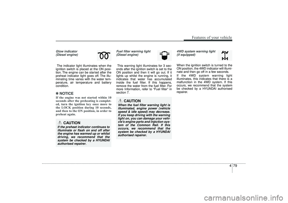
Glow indicator(Diesel engine)The indicator light illuminates when the
ignition switch is placed at the ON posi-
tion. The engine can be started after the
preheat indicator light goes off. The illu-
minating time varies with the water tem-
perature, air temperature and battery
condition.✽ ✽ NOTICEIf the engine was not started within 10
seconds after the preheating is complet-
ed, turn the ignition key once more to
the LOCK position during 10 seconds,
and then to the ON position, in order to
preheat again.
Fuel filter warning light
(Diesel engine)This warning light illuminates for 3 sec-
onds after the ignition switch is set to the
ON position and then it will go out. If it
lights up whilst the engine is running, it
indicates that water has accumulated
inside the fuel filter. If this happens,
remove the water from the fuel filter. For
more Information, refer to “Fuel filter” in
section 7.
4WD system warning light (if equipped) When the ignition switch is turned to the
ON position, the 4WD indicator will illumi-
nate and then go off in a few seconds.
If the 4WD system warning light
illuminates, this indicates that there is a
malfunction in the 4WD system. If this
occurs, we recommend that the system
be checked by a HYUNDAI authorised
repairer.
CAUTION
When the fuel filter warning light isilluminated, engine power (vehicle speed & idle speed) may decrease.If you keep driving with the warning light on, you can damage your vehi-cle's engine parts and injection sys- tem of the Common Rail. If thisoccurs, we recommend that the system be checked by a HYUNDAIauthorised repairer.
CAUTION
If the preheat indicator continues toilluminate or flash on and off after the engine has warmed up or whilstdriving, we recommend that thesystem be checked by a HYUNDAI authorised repairer.
EL(FL) UK 4A.QXP 2/9/2015 9:05 PM Page 79
Page 165 of 550

Features of your vehicle80
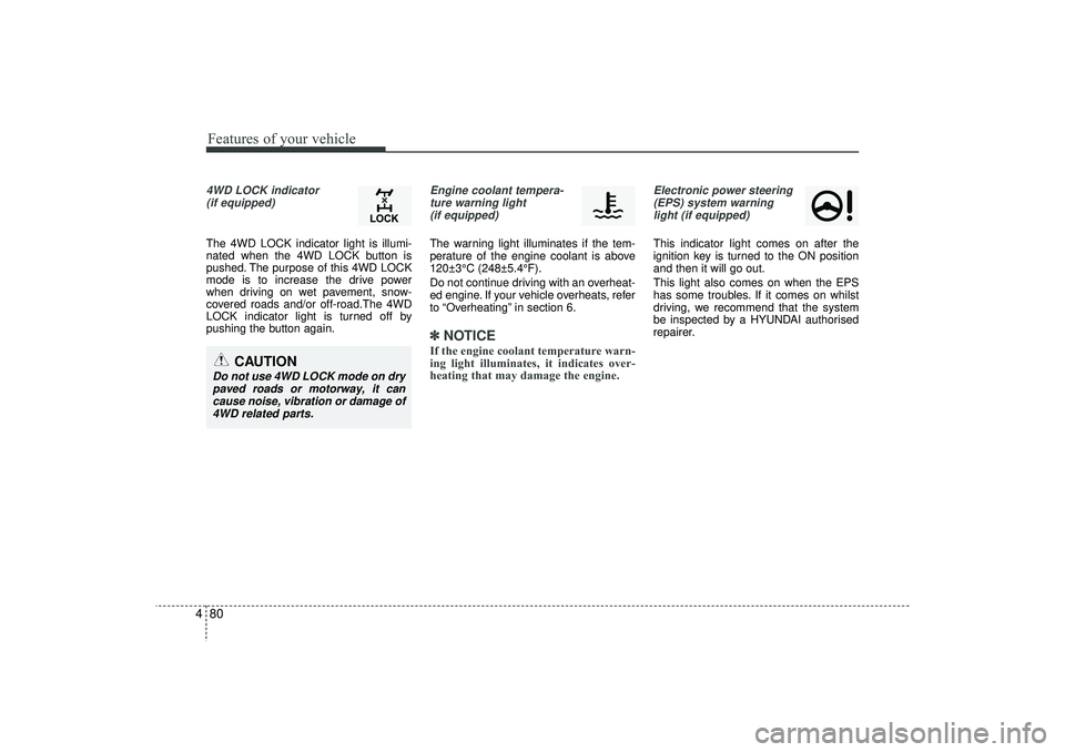
44WD LOCK indicator
(if equipped)The 4WD LOCK indicator light is illumi-
nated when the 4WD LOCK button is
pushed. The purpose of this 4WD LOCK
mode is to increase the drive power
when driving on wet pavement, snow-
covered roads and/or off-road.The 4WD
LOCK indicator light is turned off by
pushing the button again.
Engine coolant tempera-ture warning light (if equipped)The warning light illuminates if the tem-
perature of the engine coolant is above
120±3°C (248±5.4°F).
Do not continue driving with an overheat-
ed engine. If your vehicle overheats, refer
to “Overheating” in section 6.✽ ✽ NOTICEIf the engine coolant temperature warn-
ing light illuminates, it indicates over-
heating that may damage the engine.
Electronic power steering
(EPS) system warninglight (if equipped)This indicator light comes on after the
ignition key is turned to the ON position
and then it will go out.
This light also comes on when the EPS
has some troubles. If it comes on whilst
driving, we recommend that the system
be inspected by a HYUNDAI authorised
repairer.
CAUTION
Do not use 4WD LOCK mode on drypaved roads or motorway, it can cause noise, vibration or damage of4WD related parts.
EL(FL) UK 4A.QXP 2/9/2015 9:05 PM Page 80
Page 168 of 550

483
Features of your vehicle
Non-operational conditions The rear parking assist system may not
operate properly when:
1. Moisture is frozen to the sensor. (It willoperate normally when the moisture
has been cleared.)
2. The sensor is covered with foreign matter, such as snow or water, or the
sensor cover is blocked. (It will operate
normally when the material is removed
or the sensor is no longer blocked.)
3. Driving on uneven road surfaces. (unpaved roads, gravel, bumps, gradi-
ent)
4. Objects generating excessive noise (vehicle horns, loud motorcycle
engines, or truck air brakes) are within
range of the sensor.
5. Heavy rain or water spray exists.
6. Wireless transmitters or mobile phones are within range of the sensor.
7. The sensor is covered with snow.
8. Trailer towing.
9. The place light the fluorescent lamp. The detecting range may decrease
when:
1. The sensor is stained with foreign mat-
ter such as snow or water. (The sens-
ing range will return to normal when
removed.)
2. Outside air temperature is extremely hot or cold.
The following objects may not be recog-
nized by the sensor:
1. Sharp or slim objects such as ropes, chains or small poles.
2. Objects which tend to absorb the sen- sor frequency such as clothes, spongy
material or snow.
3. Undetectable objects smaller than 1 m (40 in.) in height and narrower than 14
cm (6 in.) in diameter.
Rear parking assist system precau-tions The rear parking assist system may not sound sequentially depending on
the speed and shapes of the objects
detected.
The rear parking assist system may malfunction if the vehicle bumper
height or sensor installation has been
modified or damaged. Any non-factory
installed equipment or accessories
may also interfere with the sensor per-
formance.
The sensor may not recognize objects less than 30 cm (11.8 in.) from the sen-
sor, or it may sense an incorrect dis-
tance. Use caution.
When the sensor is frozen or stained with snow, dirt, or water, the sensor
may be inoperative until the stains are
removed using a soft cloth.
Do not push, scratch or strike the sen- sor. Sensor damage could occur.
3. Undetectable objects smaller than 40 in. (1 m) in height and narrower than 6 in.
(14 cm) in diameter.
EL(FL) UK 4A.QXP 2/9/2015 9:05 PM Page 83
Page 177 of 550

Features of your vehicle92
41. Smart parking assist system
selectSelect the smart parking assist system
by pushing the button. Instruction display
of instrument cluster is displayed and the
indicator on button of this system and
front/rear parking assist system button
are illuminated.
During operating system, warning sound
is operated when objects are detected.
To turn off this system, push the button
( ) of system choice over 2 seconds.
After engine is off, if engine is turned on,
this system is on position of turning off.
If needed, push this button.
2. Parking mode selectWith applying the brake shift the
transaxle to N or D and select the
desired parking mode by pushing the
button ( ).
When system is selected, it is automati-
cally selected right side - parallel mode.
If you push the switch continuously, the
left side-parallel mode is selected. If you
push again, you can get out the smart
parking assist system mode.
3. Parking space searchAs pictures, keep distance between
parked vehicles in 0.5-1.5m constantly.
Drive slowly to desired parking space.
The parking space is searched from side
sensor automatically. If the speed is over
30km/h, notice the warning message to
driver. If the speed is over 40kn/h, the
system turns off.
When there are a lot of vehicles near
vehicle, turn on the hazard warning flash-
er to let other vehicles not be close.
If parking space is narrow, drive slowly to
desired parking space.
However, this step searches for a parking
space if your vehicle has enough space
to move except for parking space. If sat-
isfied, this system searches for parking
space.
OEL043248R
OLM043428E/OLM043429E
■
Right side
- parallel mode ■
Left side
-parallel mode
OLM043430E/OLM043431E
■
Right side
- parallel mode ■
Left side
-parallel mode
EL(FL) UK 4A.QXP 2/9/2015 9:06 PM Page 92
Page 186 of 550

4 101
Features of your vehicle
Auto light position (if equipped)When the light switch is in the AUTO light
position, the taillights and headlights will
be turned ON or OFF automatically
depending on the amount of light outside
the vehicle.
High - beam operation To turn on the high beam headlights,
push the lever away from you. Pull it back
for low beams.
The high-beam indicator will light when
the headlight high beams are switched
on.
To prevent the battery from being dis-
charged, do not leave the lights on for a
prolonged time whilst the engine is not
running.
OBK049050N
CAUTION
Never place anything over thesensor (1) located on the instru-ment panel, this will ensure better auto-light system control.
Don’t clean the sensor using a window cleaner, the cleaner mayleave a light film which could interfere with sensor operation.
If your vehicle has window tint or other types of coating on thefront windscreen, the Auto lightsystem may not work properly.
OBK049048N
WARNING
Do not use high beam when there
are other vehicles. Using high
beam could obstruct the other dri-
ver's vision.
EL(FL) UK 4A.QXP 2/9/2015 9:06 PM Page 101
Page 189 of 550

Features of your vehicle104
4Daytime running light
(if equipped)Daytime Running Lights (DRL) can make
it easier for others to see the front of your
vehicle during the day. DRL can be help-
ful in many different driving conditions,
and it is especially helpful after dawn and
before sunset.
The DRL system will make the head-
lights turn OFF when:
1. The parklight switch is ON.
2. Engine stops.
Headlight levelling device
(if equipped)To adjust the headlight beam level
according to the number of the passen-
gers and the loading weight in the lug-
gage area, turn the beam levelling switch.
The higher the number of the switch
position, the lower the headlight beam
level. Always keep the headlight beam at
the proper levelling position, or head-
lights may dazzle other road users. Listed below are the examples of proper
switch settings. For loading conditions
other than those listed below, adjust the
switch position so that the beam level
may be the nearest as the condition
obtained according to the list.
Loading condition Switch position
Driver only 0
Driver + Front passenger 0
Full passengers
(including driver) 1
Full passengers (including
driver) + Maximum permis-
sible loading 2
Driver + Maximum permis-
sible loading 3
OLM049211R
EL(FL) UK 4A.QXP 2/9/2015 9:06 PM Page 104