2016 HYUNDAI IX35 engine
[x] Cancel search: enginePage 207 of 550
Features of your vehicle122
4Air conditioning system operation tips
If the vehicle has been parked in direct
sunlight during hot weather, open the
windows for a short time to let the hot
air inside the vehicle escape.
To help reduce moisture inside of the windows on rainy or humid days,
decrease the humidity inside the vehi-
cle by operating the air conditioning
system.
During air conditioning system opera- tion, you may occasionally notice a
slight change in engine speed as the
air conditioning compressor cycles.
This is a normal system operation
characteristic.
Use the air conditioning system every month only for a few minutes to ensure
maximum system performance. When using the air conditioning sys-
tem, you may notice clear water drip-
ping (or even puddling) on the ground
under the passenger side of the vehi-
cle. This is a normal system operation
characteristic.
Operating the air conditioning system in the recirculated air position provides
maximum cooling, however, continual
operation in this mode may cause the
air inside the vehicle to become stale.
During cooling operation, you may occasionally notice a misty air flow
because of rapid cooling and humid air
intake. This is a normal system opera-
tion characteristic.
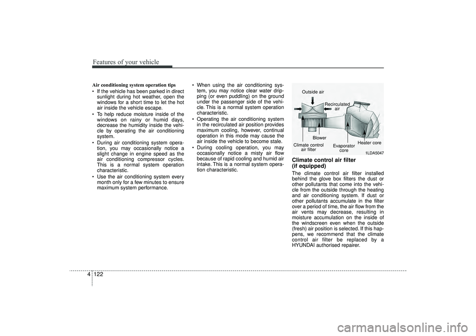
Climate control air filter
(if equipped)The climate control air filter installed
behind the glove box filters the dust or
other pollutants that come into the vehi-
cle from the outside through the heating
and air conditioning system. If dust or
other pollutants accumulate in the filter
over a period of time, the air flow from the
air vents may decrease, resulting in
moisture accumulation on the inside of
the windscreen even when the outside
(fresh) air position is selected. If this hap-
pens, we recommend that the climate
control air filter be replaced by a
HYUNDAI authorised repairer.
1LDA5047
Outside air
Recirculatedair
Climate control air filter Blower
Evaporatorcore Heater core
EL(FL) UK 4A.QXP 2/9/2015 9:08 PM Page 122
Page 209 of 550
Features of your vehicle124
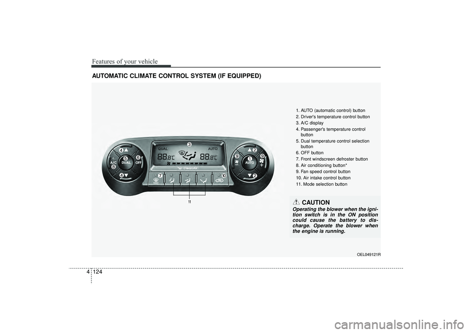
4AUTOMATIC CLIMATE CONTROL SYSTEM (IF EQUIPPED)
OEL049121R
1. AUTO (automatic control) button
2. Driver's temperature control button
3. A/C display
4. Passenger's temperature control
button
5. Dual temperature control selection button
6. OFF button
7. Front windscreen defroster button
8. Air conditioning button*
9. Fan speed control button
10. Air intake control button
11. Mode selection button
CAUTION
Operating the blower when the igni- tion switch is in the ON position could cause the battery to dis-charge. Operate the blower whenthe engine is running.
EL(FL) UK 4A.QXP 2/9/2015 9:08 PM Page 124
Page 211 of 550
Features of your vehicle126
4Manual heating and air condition-
ingThe heating and cooling system can be
controlled manually by pressing buttons
or turning knob(s) other than the AUTO
button. In this case, the system works
sequentially according to the order of
buttons or knob(s) selected.
1. Start the engine.
2. Set the mode to the desired position.
For improving the effectiveness of
heating and cooling;
- Heating:
- Cooling:
3. Set the temperature control to the desired position.
4. Set the air intake control to the outside (fresh) air position.
5. Set the fan speed control to the desired speed.
6. If air conditioning is desired, turn the air conditioning system on.
Press the AUTO button in order to con-
vert to full automatic control of the sys-
tem.
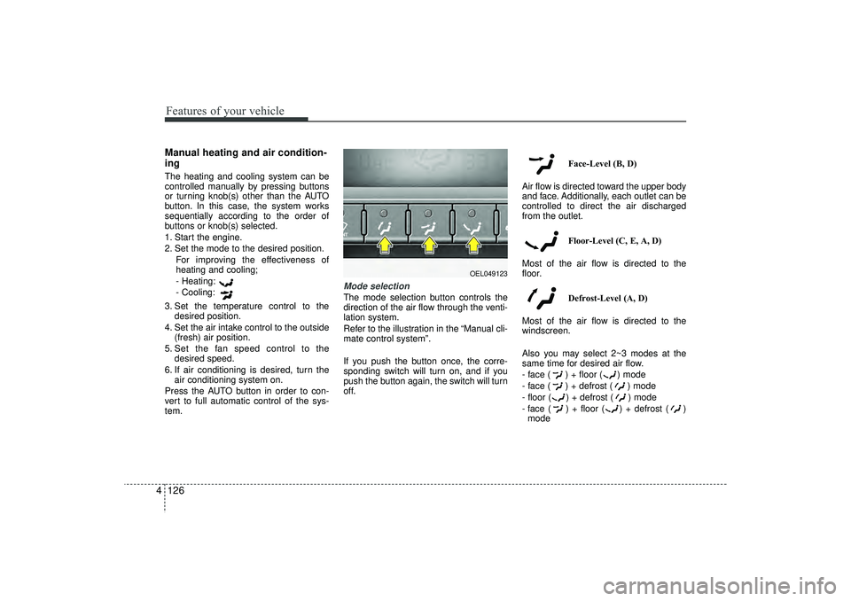
Mode selectionThe mode selection button controls the
direction of the air flow through the venti-
lation system.
Refer to the illustration in the “Manual cli-
mate control system”.
If you push the button once, the corre-
sponding switch will turn on, and if you
push the button again, the switch will turn
off. Face-Level (B, D)
Air flow is directed toward the upper body
and face. Additionally, each outlet can be
controlled to direct the air discharged
from the outlet.
Floor-Level (C, E, A, D)
Most of the air flow is directed to the
floor.
Defrost-Level (A, D)
Most of the air flow is directed to the
windscreen.
Also you may select 2~3 modes at the
same time for desired air flow.
- face ( ) + floor ( ) mode
- face ( ) + defrost ( ) mode
- floor ( ) + defrost ( ) mode
- face ( ) + floor ( ) + defrost ( ) mode
OEL049123
EL(FL) UK 4A.QXP 2/9/2015 9:08 PM Page 126
Page 224 of 550
4 139
Features of your vehicle
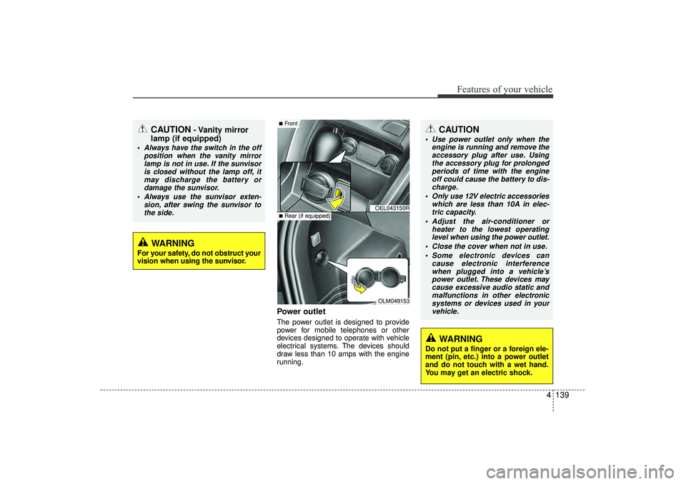
Power outletThe power outlet is designed to provide
power for mobile telephones or other
devices designed to operate with vehicle
electrical systems. The devices should
draw less than 10 amps with the engine
running.
CAUTION
- Vanity mirror
lamp (if equipped)
Always have the switch in the off
position when the vanity mirrorlamp is not in use. If the sunvisoris closed without the lamp off, itmay discharge the battery or damage the sunvisor.
Always use the sunvisor exten- sion, after swing the sunvisor tothe side.
CAUTION
Use power outlet only when the engine is running and remove theaccessory plug after use. Using the accessory plug for prolongedperiods of time with the engineoff could cause the battery to dis- charge.
Only use 12V electric accessories which are less than 10A in elec-tric capacity.
Adjust the air-conditioner or heater to the lowest operatinglevel when using the power outlet.
Close the cover when not in use. Some electronic devices can cause electronic interferencewhen plugged into a vehicle’s power outlet. These devices maycause excessive audio static and malfunctions in other electronicsystems or devices used in yourvehicle.
WARNING
Do not put a finger or a foreign ele-
ment (pin, etc.) into a power outlet
and do not touch with a wet hand.
You may get an electric shock.
WARNING
For your safety, do not obstruct your
vision when using the sunvisor.
OEL043150ROLM049153
■Front■Rear (if equipped)
EL(FL) UK 4A.QXP 2/9/2015 9:09 PM Page 139
Page 232 of 550
4 147
Features of your vehicle
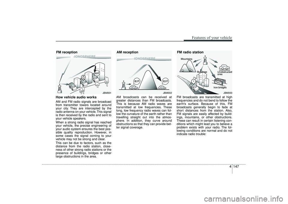
How vehicle audio worksAM and FM radio signals are broadcast
from transmitter towers located around
your city. They are intercepted by the
radio antenna on your vehicle. This signal
is then received by the radio and sent to
your vehicle speakers.
When a strong radio signal has reached
your vehicle, the precise engineering of
your audio system ensures the best pos-
sible quality reproduction. However, in
some cases the signal coming to your
vehicle may not be strong and clear.
This can be due to factors, such as the
distance from the radio station, close-
ness of other strong radio stations or the
presence of buildings, bridges or other
large obstructions in the area.AM broadcasts can be received at
greater distances than FM broadcasts.
This is because AM radio waves are
transmitted at low frequencies. These
long, low frequency radio waves can fol-
low the curvature of the earth rather than
travelling straight out into the atmos-
phere. In addition, they curve around
obstructions so that they can provide bet-
ter signal coverage.
FM broadcasts are transmitted at high
frequencies and do not bend to follow the
earth's surface. Because of this, FM
broadcasts generally begin to fade at
short distances from the station. Also,
FM signals are easily affected by build-
ings, mountains, or other obstructions.
These can result in certain listening con-
ditions which might lead you to believe a
problem exists with your radio. The fol-
lowing conditions are normal and do not
indicate radio trouble:
JBM001
JBM002
FM reception
AM reception
JBM003
FM radio station
EL(FL) UK 4B AUDIO.QXP 3/13/2015 4:19 PM Page 147
Page 237 of 550
Features of your vehicle152
4✽
✽
NOTICE -
USING THE USB
DEVICE
• To use an external USB device, make sure the device is not connected when
starting up the vehicle. Connect the
device after starting up.
• If you start the engine when the USB device is connected, it may damage
the USB device. (USB flashdrives are
very sensitive to electric shock.)
• If the engine is started up or turned off whilst the external USB device is
connected, the external USB device
may not work.
• The System may not play inauthentic MP3 or WMA files.
1) It can only play MP3 files with the compression rate between 8Kbps ~
320Kbps.
2) It can only play WMA music files with the compression rate between
8Kbps ~ 320Kbps.
• Take precautions for static electricity when connecting or disconnecting the
external USB device.
• An encrypted MP3 PLAYER is not recognizable. (Continued)(Continued)
• Depending on the condition of the
external USB device, the connected
external USB device can be unrecog-
nizable.
• When the formatted byte/sector set- ting of External USB device is not
either 512BYTE or 2048BYTE, then
the device will not be recognized.
• Use only a USB device formatted to FAT 12/16/32.
• USB devices without USB I/F authen- tication may not be recognizable.
• Make sure the USB connection termi- nal does not come in contact with the
human body or other objects.
• If you repeatedly connect or discon- nect the USB device in a short period
of time, it may break the device.
• You may hear a strange noise when connecting or disconnecting a USB
device. (Continued)(Continued)
• If you disconnect the external USB
device during playback in USB mode,
the external USB device can be dam-
aged or may malfunction. Therefore,
disconnect the external USB device
when the audio is turned off or in
another mode. (e.g, Radio, CD)
• Depending on the type and capacity of the external USB device or the type of
the files stored in the device, there is a
difference in the time taken for recog-
nition of the device.
• Do not use the USB device for purpos- es other than playing music files.
• Playing videos through the USB is not supported.
• Use of USB accessories such as rechargers or heaters using USB I/F
may lower performance or cause trou-
ble. (Continued)
EL(FL) UK 4B AUDIO.QXP 3/13/2015 4:19 PM Page 152
Page 297 of 550
Features of your vehicle212
4✽
✽
NOTICE - USING THE USB
DEVICE• Connect the USB device after turning
on the engine. The USB device may
become damaged if it is already con-
nected when the ignition is turned
on.The USB device may not operate
properly if the car ignition is turned
on or off with the USB device connect-
ed.
• Heed caution to static electricity when connecting/disconnecting USB
devices.
• Encoded MP3 Players will not be rec- ognized when connected as an exter-
nal device.
• When connecting an external USB device, the device may not properly
recognize the USB is in some states.
• Only products formatted with byte/sectors under 64Kbyte will be
recognized.
• This device recognizes USB devices formatted in FAT 12/16/32 file for-
mats. This device does not recognize
files in NTFS file format. (Continued)(Continued)
• Some USB devices may not be sup-
ported due to compatibility issues.
• Avoid contact between the USB con- nector with bodily parts or foreign
objects.
• Repeated connecting/disconnecting of USB devices within short periods of
time may result in product malfunc-
tion.
• A strange noise may occur when dis- connecting the USB.
• Make sure to connect/disconnect external USB devices with the audio
power turned off.
• The amount of time required to recog- nize the USB device may differ
depending on the type, size or file for-
mats stored in the USB. Such differ-
ences in time are not indications of
malfunctions.
• The device only supports USB devices used to play music files.
• USB images and videos are not sup- ported. (Continued)(Continued)
• Do not use the USB I/F to charge bat-
teries or USB accessories that gener-
ate heat. Such acts may lead to wors-
ened performance or damage to the
device.
• The device may not recognize the USB device if separately purchased USB
hubs and extension cables are being
used. Connect the USB directly with
the multimedia terminal of the vehi-
cle.
• When using mass storage USB devices with separate logical drives, only files
saved to the root drive can be played.
• Files may not properly operate if application programs are installed to
the USBs.
• The device may not operate normally if MP3 Players, mobile phones, digital
cameras, or other electronic devices
(USB devices not recognized as
portable disk drives) are connected
with the device. (Continued)
EL(FL) UK 4B AUDIO.QXP 3/13/2015 4:19 PM Page 212
Page 349 of 550
Driving your vehicle
5
Before driving . . . . . . . . . . . . . . . . . . . . . . . . . . . . . . 5-4• Before entering vehicle . . . . . . . . . . . . . . . . . . . . . . . . . 5-4
• Necessary inspections . . . . . . . . . . . . . . . . . . . . . . . . . 5-4
• Before starting . . . . . . . . . . . . . . . . . . . . . . . . . . . . . . . 5-4Key positions . . . . . . . . . . . . . . . . . . . . . . . . . . . . . . . 5-5• Illuminated ignition switch . . . . . . . . . . . . . . . . . . . . . 5-5
• Ignition switch position . . . . . . . . . . . . . . . . . . . . . . . . . 5-6
• Starting the engine . . . . . . . . . . . . . . . . . . . . . . . . . . . . 5-7Engine start/stop button . . . . . . . . . . . . . . . . . . . . . 5-9• Illuminated engine start/stop button . . . . . . . . . . . . . . 5-9
• Engine start/stop button position. . . . . . . . . . . . . . . . . 5-9
• Starting the engine . . . . . . . . . . . . . . . . . . . . . . . . . . . 5-12ISG (Idle Stop and Go) system . . . . . . . . . . . . . . 5-15• Auto stop . . . . . . . . . . . . . . . . . . . . . . . . . . . . . . . . . . . 5-\
15
• Auto start . . . . . . . . . . . . . . . . . . . . . . . . . . . . . . . . . . . 5-\
16
• Condition of ISG system operation . . . . . . . . . . . . . . 5-17
• ISG system deactivation . . . . . . . . . . . . . . . . . . . . . . . 5-17
• ISG system malfunction . . . . . . . . . . . . . . . . . . . . . . . 5-18Manual transaxle . . . . . . . . . . . . . . . . . . . . . . . . . . 5-19• Manual transaxle operation . . . . . . . . . . . . . . . . . . . . 5-19
• Good driving practices . . . . . . . . . . . . . . . . . . . . . . . . 5-21Automatic transaxle . . . . . . . . . . . . . . . . . . . . . . . 5-22• Automatic transaxle operation. . . . . . . . . . . . . . . . . . 5-23
• Good driving practices . . . . . . . . . . . . . . . . . . . . . . . . 5-27
Four wheel drive (4WD) . . . . . . . . . . . . . . . . . . . . 5-28• Tight corner brake effect . . . . . . . . . . . . . . . . . . . . . . 5-28
• Four Wheel Drive (4WD) transfer mode selection . 5-29
• For safe four-wheel drive operation . . . . . . . . . . . . 5-30
• Reducing the risk of a rollover . . . . . . . . . . . . . . . . . 5-32Brake system . . . . . . . . . . . . . . . . . . . . . . . . . . . . . . 5-35• Power brakes . . . . . . . . . . . . . . . . . . . . . . . . . . . . . . . 5-35
• Parking brake . . . . . . . . . . . . . . . . . . . . . . . . . . . . . . 5-36
• Anti-lock brake system (ABS) . . . . . . . . . . . . . . . . . . 5-38
• Electronic stability control (ESC) . . . . . . . . . . . . . . . 5-41
• Vehicle stability management (VSM) . . . . . . . . . . . . 5-44
• Hill-start assist control (HAC) . . . . . . . . . . . . . . . . . . 5-45
• Downhill brake control (DBC) . . . . . . . . . . . . . . . . . 5-46
• Emergency stop signal (ESS) . . . . . . . . . . . . . . . . . . . 5-47
• Trailer stability assist (TSA) . . . . . . . . . . . . . . . . . . . 5-47
• Good braking practices. . . . . . . . . . . . . . . . . . . . . . . . 5-48Cruise control system . . . . . . . . . . . . . . . . . . . . . . 5-50• To set cruise control speed . . . . . . . . . . . . . . . . . . . . . 5-51
• To increase cruise control set speed. . . . . . . . . . . . . . 5-51
• To decrease the cruising speed . . . . . . . . . . . . . . . . . . 5-52
• To temporarily accelerate with the cruise control on . . . . . . . . . . . . . . . . . . . . . . . . 5-52
• To cancel cruise control, do one of the following . . . 5-52
• To resume cruising speed at more than approximately 25 mph (40 km/h) . . . . . . . . . . . . . . 5-53
EL(FL) UK 5.QXP 12/16/2014 8:08 PM Page 1