2016 Hyundai H350 Time
[x] Cancel search: TimePage 46 of 473

2-26
Safety system of your vehicle
How does the air bag operate?
Air bags are activated (able toinflate if necessary) only when the
ignition switch is turned to the ON
or START position.
Air bags instantly inflate in the event of a serious frontal collisionin order to help protect the occu-
pants from serious physical injury.
There is no single speed at which the air bags will inflate.
Generally, air bags are designed to inflate in accordance with the
severity of a collision and its direc-
tion. These two factors determinewhether the sensors produce an
electronic deployment/inflation sig-nal.
Air bag deployment depends on a number of factors, including a driv-
ing speed, an impact angle, a vehi-cle density/stiffness or a colliding
object, which your vehicle strikes
with in a collision. Those factorsare not limited to those mentioned
above. The front air bags will completely
inflate and deflate in an instant.
It is virtually impossible for you to
observe the inflation of the air bags
during an accident.
It is more likely that you will simply see the deflated air bags hanging
out of the air-bag storage compart-ments after a collision.
In order to protect occupants in a severe collision, the air bags must
rapidly inflate. The speed of air baginflation is a consequence of the
extremely short colliding time as
well as the necessity to inflate the
air bag between the occupant and
the vehicle structure before the
occupant strikes with the vehicle
structure. This fast inflating speed
reduces the risk of serious or life-
threatening injury in a severe colli-
sion. This is the core part indesigning an air bag.
However, air bag inflation may also
cause injury, such as a facial abra-
sion, a bruise and a broken bones,
because the air bags expand with
a great deal of force.
There are certain circumstances
under which the air bag installed
in the steering wheel may cause
fatal injury, especially when the
occupant is positioned exces-
sively close to the steeringwheel.
To avoid severe personal
injury or death caused by
deploying air bags in a colli-
sion, the driver should sit in
the rearmost position from
the air bag installed in thesteering wheel (at least 250
mm (10 inches) away). The
front passengers should
always move their seats as far
back as possible and sit backin their seats.
Air bags instantly inflate in
the event of a collision. Thus,
passengers may be injured by
the inflating air bag, when
they are in an improper posi-tion.
Air bag inflation may cause
injury, such as facial/bodily
abrasions, injuries by broken
glasses, or skin burns.
WARNING
Page 52 of 473
2-32
Safety system of your vehicle
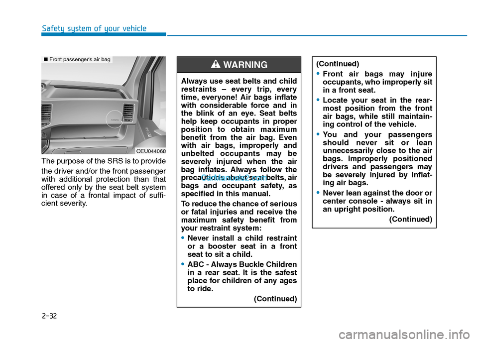
The purpose of the SRS is to provide
the driver and/or the front passenger with additional protection than that
offered only by the seat belt systemin case of a frontal impact of suffi-
cient severity.Always use seat belts and child
restraints – every trip, every
time, everyone! Air bags inflate
with considerable force and in
the blink of an eye. Seat belts
help keep occupants in proper
position to obtain maximum
benefit from the air bag. Even
with air bags, improperly and
unbelted occupants may be
severely injured when the air
bag inflates. Always follow the
precautions about seat belts, air
bags and occupant safety, as
specified in this manual.
To reduce the chance of serious or fatal injuries and receive the
maximum safety benefit from
your restraint system:
Never install a child restraint
or a booster seat in a front
seat to sit a child.
ABC - Always Buckle Children
in a rear seat. It is the safest
place for children of any ages
to ride.
(Continued)
WARNING
OEU044068
■Front passenger's air bag
(Continued)
Front air bags may injure
occupants, who improperly sit
in a front seat.
Locate your seat in the rear-
most position from the front
air bags, while still maintain-
ing control of the vehicle.
You and your passengers
should never sit or lean
unnecessarily close to the air
bags. Improperly positioned
drivers and passengers may
be severely injured by inflat-
ing air bags.
Never lean against the door or
center console - always sit inan upright position.
(Continued)
Page 64 of 473
Instrument cluster................................................3-43Instrument panel illumination .......................................3-44
Gauges and indicators ...................................................3-44
Multi-display ........................................................3-50 Main display .....................................................................3-50
Function description .......................................................3-51
Trip computer ...................................................................3-53
Drive info. mode ..............................................................3-53
AV information .................................................................3-53
Turn by turn navigation.................................................3-54
Information Mode ...........................................................3-54
User Settings Mode ........................................................3-55
Warning Messages..........................................................3-57
Trip computer .......................................................3-60 Overview............................................................................3-60
Trip modes ........................................................................3-61
Driving distance/average vehicle speed/
elapsed time .....................................................................3-62 Fuel economy ...................................................................3-63
Urea Solution Gauge ......................................................3-65
Total AUTO STOP Hour..................................................3-66
Driving Information .........................................................3-66
Warning and indicator lights ..............................3-66 Digital tachograph................................................3-80
Type A ................................................................................3-80
Type B ................................................................................3-82
Parking assist system..........................................3-88 Rear parking assist system type .................................3-89
Front/rear parking assist system type......................3-92
Rearview camera..................................................3-94
Hazard warning flasher ......................................3-95
Lighting..................................................................3-95 Battery saver function ..................................................3-95
Headlight escort function .............................................3-96
Headlight welcome function.........................................3-96
Lighting control ...............................................................3-96
High - beam operation ..................................................3-98
Turn signals and lane change signals ........................3-99
Front fog light ...............................................................3-100
Rear fog light .................................................................3-100
Daytime running light ..................................................3-101
Headlight leveling device ............................................3-101
Wipers and washers ..........................................3-102 Windshield wiper/washer ...........................................3-102
Windshield wipers .........................................................3-102
Windshield washers ......................................................3-105
3
Page 74 of 473

3-12
Convenient features of your vehicle
In cold and wet climates, doorlock and door mechanisms may
not work properly due to freez-ing conditions.
If the door is locked/unlocked multiple times in rapid succes-
sion with either the vehicle key
or door lock switch, the system
may stop operating temporarily
in order to protect the circuit
and prevent damage to systemcomponents.
Operating door locks from
inside the vehicle
With the door lock button
To unlock front driver's door andfront passenger's door, press the
unlock switch (1).
To lock front driver's door and front passenger's door, press the lock
switch (2).
To open a door, pull the door han- dle outward. If the inner door handle of all doors
are pulled when the door lock but-
ton is in the lock position, the but-
ton will unlock and the door will
open. (if equipped)
Front doors cannot be locked if the ignition key is in the ignition switch
and any front door is opened.
NOTICE
If you don't close the door
securely, the door may open
again.
Be careful that someone's
body and hands are not
trapped when closing the
door.
WARNING OEU045008
■Driver’s doors
Page 82 of 473

3-20
The emergency measures,
which you may take in case ofthe electrical-step failures.
The step friction surface is con-taminated with the foreign sub-
stances.
The electrical step may not normally
operate, when its friction surface is
contaminated. Repetitively operate
either the step switch or the mid-slid-
ing door 2-to-3 times. When the step
operation completely stops for the
same reason, manually push in the
step and turn OFF the switch.
Remove the foreign substances with
washing equipment at a vehicle
wash (Refer to the regular cleaning
in the chapter 3). Then, turn ON the
step switch, and operate the mid-
sliding door. When the electrical step
does not still normally operate, we
recommend that the electrical step
be checked by an authorized
HYUNDAI dealer.
Step does not operate, after being extended out.
Hold the step in position with the R-
clip, as explained below. Then, turn
OFF the switch and visit a near-by
Hyundai dealer for repair services.
When you hear the warning alarm
while driving, you may stop the alarm
by disconnecting the electrical step
fuse located in the fuse box under
the left side of the driver's seat.
Hold the step in position with the
R-clip
1. Pull R-clips (3) on both rods (1) on the underside of the step out of
their respective pins. Remove
washers (2) and detach both rods(1).
Convenient features of your vehicle
OEU044078
Page 83 of 473
3-21
Convenient features of your vehicle
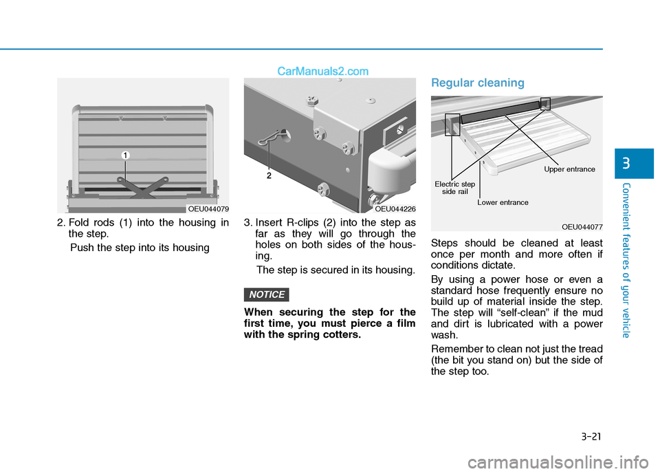
2. Fold rods (1) into the housing inthe step.
Push the step into its housing 3. Insert R-clips (2) into the step as
far as they will go through the holes on both sides of the hous-ing.
The step is secured in its housing.
When securing the step for the
first time, you must pierce a film
with the spring cotters.
Regular cleaning
Steps should be cleaned at least once per month and more often if
conditions dictate.
By using a power hose or even a standard hose frequently ensure no
build up of material inside the step.
The step will “self-clean” if the mud
and dirt is lubricated with a power
wash. Remember to clean not just the tread
(the bit you stand on) but the side of
the step too.
NOTICE
3
OEU044079OEU044226
OEU044077
Electric step side rail
Lower entrance Upper entrance
Page 97 of 473
3-35
Convenient features of your vehicle
To open the urea solution filler lid;
1.Open the urea solution filler lid.
2.To remove the cap, turn the ureasolution tank cap counterclock-
wise.
3.Refill as needed.
After completely filling, urea solu-
tion in the tank, refill urea solution
every 10,000 km.
NOTICE3
If the vehicle is driven with
urea solution volume less
than 4%, engine output will belimited.
REFILL IN GOOD TIME
The reducing agent must be replenished as soon as the
urea level warning lamp illu-
minates or blinks, otherwise
either engine torque or vehi-
cle speed can be limited. (Continued)
CAUTION
When opening the urea solu- tion tank cap at high outside
temperatures, ammonia
vapors may escape. Ammonia
vapors have a pungent smell
and primarily cause irritationof the: - Skin- Mucous membranes
- Eyes
You may experience a burning
sensation in your eyes, nose
and throat, as well as cough-
ing and watering of the eyes. Do not inhale ammonia
vapors. Do not allow ureasolution to come in direct
contact with your skin. It is
hazardous to your health.
Wash any affected areas off
with plenty of clean water. If
necessary, consult a doctor.
(Continued)
WARNING(Continued)
Liquid that are not recom-
mended such as diesel, gaso-
line, and alcohol shall neverbe used other than the recom-mended urea solution thatsatisfy ISO22241 or DIN70070.
Driver must use with a reduc-
ing agent UREA solution for
the SCR system working
properly. In order to complywith emissions regulations,
the vehicle must be operatedusing UREA solution.
If driver is driving a vehicle without using a UREA solu-
tion, driving permit may be
revoked, in some countries
you may be a criminal
offense, such as road traffic
offenses.
Page 98 of 473
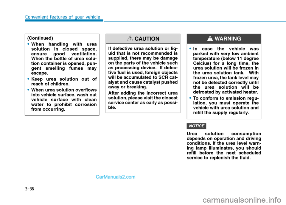
3-36Urea solution consumption depends on operation and driving
conditions. If the urea level warn-
ing lamp illuminates, you should
refill before the next scheduled
service to replenish the fluid.
NOTICE
Convenient features of your vehicle
In case the vehicle was
parked with very low ambient
temperature (below 11 degree
Celcius) for a long time, the
urea solution will be frozen in
the urea solution tank. With
frozen urea, the tank level may
not be detected correctly untilthe urea solution will be
defrosted by activated heater.
To conform to emission regu-
lation, you must operate the
vehicle with urea solution and
refill the supply regularly.
WARNING
If defective urea solution or liq- uid that is not recommended is
supplied, there may be damage
on the parts of the vehicle such
as processing device. If defec-
tive fuel is used, foreign objects
will be accumulated to SCR cat-
alyst and cause catalyst pushed
away or breaking.
After adding the incorrect urea
solution, please visit the closest
service center as early as possi-
ble.
CAUTION(Continued)
When handling with urea
solution in closed space,ensure good ventilation.When the bottle of urea solu-
tion container is opened, pun-
gent smelling fumes may
escape.
Keep urea solution out of
reach of children.
When urea solution overflows
into vehicle surface, wash out
vehicle surface with clean
water to prohibit corrosion
from occurring.