Page 65 of 84

Monitors the tire pressure while you are driving.
If your vehicle’s tire pressur")
122 || 123
HANDLING THE UNEXPECTEDHANDLING THE UNEXPECTED
Tire Pressure Monitoring System (TPMS)
Monitors the tire pressure while you are driving.
If your vehicle’s tire pressure becomes significantly
low, the low tire pressure indicator comes on and a
message appears on the multi-information display*.
What to Do
Stop your vehicle in a safe place. Check the tire
pressure and adjust the pressure to the specified
level on the label on the driver’s doorjamb.
*if equipped
TPMS Calibration
Any time you inflate, change, or rotate one or more of the tires, you \
need to
recalibrate the system. The calibration process requires approximately 30 minutes
of cumulative driving at speeds between 30–60 mph (48–97 km/h). The vehicle
must be stopped to begin calibration, and the process finishes automatically.
Using the TPMS button*
Press and hold the TPMS button near the steering
wheel. The TPMS indicator blinks twice, and
calibration begins.
Using the Settings menu*
Use the selector knob or touchscreen to make and enter selections.
1. Models with one display: Press the SETTINGS
button. Select Vehicle Settings.
Models with touchscreen: From the HoMe
screen, select Settings. Select vehicle.
2. Select TPMS Calibration.
3. Select Calibrate, and calibration begins.
Using the multi-information display*
Use the Info (p/q) and SEL/RESET buttons on the steering wheel to make and
enter selections.
1. Scroll to the vehicle Settings screen, and select it.
2. Select TPMS Calibration.
3. Select Calibrate, and calibration begins.
Tire Pressure Monitoring System (TPMS) - Required Federal Explanation
U.S. models
Each tire, including the spare (if provided), should be checked monthly
when cold and inflated to the inflation pressure recommended by the
vehicle manufacturer on the vehicle placard or tire inflation pressure\
label.
(If your vehicle has tires of a different size than the size indicated on the
vehicle placard or tire inflation pressure label, you should determine the
proper tire inflation pressure for those tires.)
As an added safety feature, your vehicle has been equipped
with a tire pressure monitoring system (TPMS) that illuminates
a low tire pressure telltale when one or more of your tires is
significantly underinflated.
Accordingly, when the low tire pressure telltale illuminates, you should
stop and check your tires as soon as possible, and inflate them to the
proper pressure.
Driving on a significantly underinflated tire causes the tire to ove\
rheat and
can lead to tire failure. Underinflation also reduces fuel efficienc\
y and tire
tread life, and may affect the vehicle’s handling and stopping ability.
Please note that the TPMS is not a substitute for proper tire maintenance,
and it is the driver’s responsibility to maintain correct tire pressure, even
if underinflation has not reached the level to trigger illumination of\
the
TPMS low tire pressure telltale.
Your vehicle has also been equipped with a TPMS malfunction indicator
to indicate when the system is not operating properly. The TPMS
malfunction indicator is combined with the low tire pressure telltale.
When the system detects a malfunction, the telltale will flash for
approximately one minute and then remain continuously illuminated. This \
sequence will continue upon subsequent vehicle start-ups as long as the
malfunction exists.
When the malfunction indicator is illuminated, the system may not be able
to detect or signal low tire pressure as intended.
TPMS malfunctions may occur for a variety of reasons, including the
installation of replacement or alternate tires or wheels on the vehicle \
that
prevent the TPMS from functioning properly.
Always check the TPMS malfunction telltale after replacing one or more
tires or wheels on your vehicle to ensure that the replacement or altern\
ate
tires and wheels allow the TPMS to continue to function properly.
Driving on an extremely underinflated tire can cause it to overheat. A\
n overheated
tire can fail. Always inflate your tires to the specified pressure.
NOTICE
Page 66 of 84

124 || 125
HANDLING THE UNEXPECTEDHANDLING THE UNEXPECTED
Changing a Flat Tire
If a tire goes flat while driving, grasp the steering wheel firmly, and brake gradually
to reduce speed. Then, stop in a safe place. replace the flat tire with the compact
spare tire. Go to a dealer as soon as possible to have the full-size tire repaired or
replaced.
Getting Ready to Change the Tire
Park the vehicle on a firm, level, non-slippery surface. Apply the parking brake,
shift to Park (P), and turn the vehicle off. Turn on the hazard warning lights.
1. open the trunk floor lid.
2. Take the tool case out of the trunk. Take the jack
and wheel nut wrench out of the tool case.
3. Unscrew the wing bolt, then remove the spacer
cone. remove the spare tire.
4. Place the compact spare tire (wheel side up)
under the vehicle body, near the tire that needs
to be replaced.
5. Loosen each wheel nut about one turn using the
wheel nut wrench.
Tool case
Spare tire
Setting Up the Jack
1. Place the jack under the jacking point closest to
the tire to be changed.
2. Turn the end bracket clockwise (as shown in
the image) until the top of the jack contacts the
jacking point. Make sure that the jacking point
tab is resting in the jack notch.
3. Raise the vehicle, using the jack handle bar and
the jack handle, until the tire is off the ground.
Jacking points
Jacking point
Jack
handle
ba r Wheel nu
t
Wrench as jack handle
The vehicle can easily roll off the jack, seriously injuring anyone unde\
rneath.
Follow the directions for changing a tire exactly, and never get under the
vehicle when it is supported only by the jack.
WARNING
The following instructions must be followed to use the jack safely:
• Do not use the jack with people or luggage in the vehicle.
• Use the jack provided in your vehicle. other jacks may not support the weight
(“load”) or fit the jacking point.
• Do not use while the engine is running.
• Use only where the ground is firm and level.
• Use only at the jacking points.
• Do not get in the vehicle while using the jack.
• Do not put anything on top of or underneath the jack.
Page 67 of 84

126 || 127
HANDLING THE UNEXPECTEDHANDLING THE UNEXPECTED
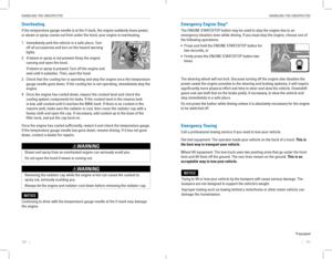
Replacing the Flat Tire
1. remove the wheel nuts and flat tire.
2. Mount the compact spare tire. replace the
wheel nuts, and lightly tighten them.
3. Lower the vehicle and remove the jack. Tighten
the wheel nuts in the order indicated in the
image. Go around, tightening the nuts, two to
three times in this order. Do not overtighten the
wheel nuts.
If you drive with the spare tire installed, the
low tire pressure/TPMS indicator appears. The
indicator stays on until a regular tire is installed.
Storing the Flat Tire
1. remove the center cap.
2. open the trunk. Place the flat tire face down in
the spare tire well.
3. Remove the spacer cone from the wing bolt, flip
it over, and insert it back on the bolt. Secure the
flat tire with the wing bolt.
4. Securely put the jack and wheel nut wrench back
in the tool case. Store the case in the trunk.
Spacer coneWing bolt
For
compact
spare tire For
full-size
tire
Loose items can fly around the interior in a crash and can seriously i\
njure the
occupants.
Store the wheel, jack, and tools securely before driving.
WARNING
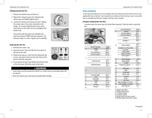
Fuse Locations
If any electrical devices are not working, turn the vehicle off and check to see if any
applicable fuse is blown. Fuse locations are shown on the fuse box cover. Locate the
fuse in question by the fuse number and box cover number.
Engine Compartment Fuse Box
Located under the hood near the brake fluid reservoir. Push the tabs to open the
box.
*if equipped*1
: Models with LKA S
*2 : Models without LKAS
*3 : 4-cylinder models
*4 : 6-cylinder models
Circuit ProtectedAmps1Battery125A
2
EPS70 A
Fuse Box Main 1(60 A)Fuse Box Option 1(40A )����
ABS/VSA FSR 20
A*1
40A*2
ABS/VSA Motor 40
A*1
30A*2
3
��������
4F ront Fog Ligh t*(10A )5Horn10A
6S top Light10A7FI Sub15A
8D RL(7.5A)
9IG Coi l15A
10 Injector*3
�*4(2
0A )*3
�*4
*5: M odels with smart entry syste m
*6: Models without smart entry system Circuit Protected
Amps
11 Hazard 15A
12 Fuse Box Main
260A
Fuse Box Option 2(40A)
IG Main 1 30
A
*5
50A*6
IG Main 2*5
�*630A*5
�*6
Sub Fan Moto r20
A*3
30A*4
Headlight Low Beam Main 30A
Fuse Bo x3 0A
Wiper Moto r3 0A
Main Fan Motor 30A
Starter Motor
*5
�*630 A*5
�*6
13 Rear Defogger 40A
14 Heater Moto r4 0A
15 FI Main 15A
16 Heated Door Mirror
*, *3
�*4(10
A)*3
�*4
17 MG Clutch 7.5A
18 DBW1 5A
19 Small Light 20A
20 Interior Light 7.5A
21 Back Up 10A
22 Audio1 0A
23 Fan Timer 7.5A
24 Right Headlight Low Beam 10A
25 Left Headlight Low Beam 10A
26 ABS/VSA EC
U
*1
�*27.5A*1
�*2
*1: Models with LKA S
*2 : Models without LKAS
*3 : 4-cylinder models
*4 : 6-cylinder models
Circuit Protected Amps
1 Battery 125A
2 EPS
70A
Fuse Box Main 1(60A)
Fuse Box Option 1(40A )
��
� �
ABS/VSA FSR 20
A
*1
40A*2
ABS/VSA Motor 40
A*1
30A*2
3 �
�
� �
� �
� �
4F ront Fog Ligh t
*(10A )
5 Horn 10A
6S top Light1 0A
7 FI Sub 15A
8D RL(7.5A)
9 IG Coil 15A
10 Injector
*3
�*4(2
0A )*3
�*4
*5: M odels with smart entry syste m
*6: Models without smart entry system
Circuit ProtectedAmps11Hazard15 A
12 Fuse Box Main 260A
Fuse Box Option 2(40A)
IG Main 1 30
A
*5
50A*6
IG Main 2*5
�*630A*5
�*6
Sub Fan Moto r20
A*3
30A*4
Headlight Low Beam Main 30A
Fuse Box30A
Wiper Motor30A
Main Fan Motor 30A
Starter Motor
*5
�*630 A*5
�*6
13Rear Defogger40A
14 Heater Motor40A15FI Main15A
16 Heated Door Mirror*, *3
�*4(10
A)*3
�*4
17MG Clutch7.5A
18 DBW15A19Small Light20A
20 Interior Light 7.5A
21Back Up10 A
22 Audio10A23Fan Timer7.5A
24 Right Headlight Low Beam 10A
25Left Headlight Low Beam10A
26 ABS/VSA EC
U*1
�*27.5A*1
�*2
Page 68 of 84

128 || 129
HANDLING THE UNEXPECTEDHANDLING THE UNEXPECTED
Interior Fuse Box
Located under the dashboard on the driver’s side.
*if equipped
Circuit ProtectedAmps1A/C7.5A2DRL7.5A3��4��5Meter7.5A6SRS7.5A7Optio n(7.5A)8MISS SOL10A9Fuel Pump20A10ABS/VSA7.5A11��12Front Wipe r7.5A13ACG15 A
14Rear Accessory Power Socket
(Console Compartment)(2 0A )
15Driver’s Power Seat
Reclining*(2 0A )
16Moonroof*(20A )17Front Seat Heaters*(20A )18��
19Passenger Side Door
Unlock10A
20 Driver Side Rear Door
Unlock 10
A
21 Driver’s Door Lock 10A
22 Passenger Side Door Lock 10A
23 Driver’s Door Unlock 10A
24 SRS 10A
25 Illumination 10A
26 Key Lock 7.5A
27 Parking Lights 10A
28 Lumbar Suppor t
*(10A )
29 Right Headlight High Beam 10A
30 Washer 15A
31 SMART
*(10A )
32 Driver’s Power Window 20A
33 Front Passenger’s Power
Window 20
A
34 Rear Driver Side Power
Window 20
A
35 Rear
Passenger Side Power
Windo w 20
A
36 Driver’s Power Seat Sliding
*(20A)
37 ACCESSORY 7.5A
38 � �
39 Left Headlight High Beam 10A
40
Front Accessory Power Socket
(Con sole Panel)20A
41 Driver Side Rear Door Lock 10A
42 Door Lock 20A
a Audio
*(7.5A)
b ACM*(20 A)
c Rear Seat Heaters*(15A)
d Premium Am p*(20A)
e � �
f � �
g Passenger’s Power Seat
Reclining
*(20A)
h Passenger’s Power Seat
Sliding
*(20A)
Circuit Protected Amps
*
*
* * *
Fuse label
Circuit Protected Amps
1 A/C 7.5A
2 DRL 7.5A
3 � �
4 � �
5 Meter 7.5A
6 SRS 7.5A
7 Option (7.5A)
8 MISS SOL 10A
9 Fuel Pump 20A
10 ABS/VSA 7.5A
11 � �
12 Front Wiper 7.5A
13 ACG 15A
14
Rear Accessory Power Socket
(Console Compartment)(2 0A )
15 Driver’s Power Seat
Reclining
*(2 0A )
16 Moonroof
*(20A )
17 Front Seat Heaters*(20A )
18 � �
19 Passenger Side Door
Unlock 10
A
20 Driver Side Rear Door
Unlock 10
A
21Driver’s Door Lock10A22Passenger Side Door Lock10A23Driver’s Door Unlock10A24SRS10A25Illumination10A26Key Lock7.5A27Parking Lights10 A28Lumbar Suppor t*(10A )29Right Headlight High Beam10A30Washe r15A31SMART*(10A )32Driver’s Power Window20A
33Front Passenger’s Power
Window20A
34Rear Driver Side Power
Window20A
35Rear Passenger Side Power
Windo w20A
36Driver’s Power Seat Sliding*(20A)37ACCESSORY7.5A38��39Left Headlight High Beam10A
40Front Accessory Power Socket
(Con sole Panel)20A
41Driver Side Rear Door Lock10A42Door Lock20AaAudio*(7.5 A)bACM*(20 A)cRear Seat Heaters*(15A)dPremium Am p*(20A)e��f��
gPassenger’s Power Seat
Reclining*(20A)
hPassenger’s Power Seat
Sliding*(20A)
Circuit ProtectedAmps
*
*
* * *
Inspecting and Changing Fuses
1. Turn the vehicle off, including all lights and
accessories.
2. Remove the fuse box cover.
3. Check the large fuse in the engine compartment.
If the fuse is blown, use a Phillips-head
screwdriver to remove the screws and replace
the fuse with a new one. reinstall the screws.
4. Inspect the small fuses in the engine
compartment and the vehicle interior.
If there is a burned out fuse, remove it with the
fuse puller and replace it with a new one.
Combined
fuse Blown fuse
Fuse puller
replacing a fuse with one that has a higher rating greatly increases the \
chances of
damaging the electrical system.
NOTICE
Page 69 of 84

130 || 131
MAINTENANCEMAINTENANCE
MAINTENANCE
Learn about basic maintenance that you can perform on the vehicle yourself, as well
as information about how to best maintain the vehicle.
Safety Precautions
Some of the most important safety precautions are listed below; however, we cannot
warn you of every conceivable hazard that can arise in performing maintenance.
only you can decide whether or not you should perform a given task.
Maintenance Safety
• To reduce the possibility of fire or explosion, keep cigarettes, sparks, and flames
away from the battery and all fuel-related parts.
• Never leave rags, towels, or other flammable objects under the hood.
• To clean parts, use a commercially available degreaser or parts cleaner, not
gasoline.
• Wear eye protection and protective clothing when working with the battery or
compressed air.
• Do not run the engine in confined spaces where carbon monoxide gas can
accumulate.
Vehicle Safety
• The vehicle must be stationary, and parked on level ground with the parking
brake set and the engine off.
• Be aware that hot parts can burn you.
• Be aware that moving parts can injure you.
Improperly maintaining this vehicle or failing to correct a problem before
driving can cause a crash in which you can be seriously hurt or killed.
Always follow the inspection and maintenance recommendations according
to the schedules in this guide.
WARNING
Failure to properly follow maintenance instructions and precautions can \
cause you to be seriously hurt or killed.
Always follow the procedures and precautions in this guide.
WARNING
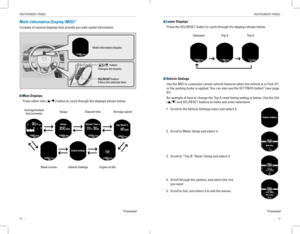
Maintenance Minder™
reminds you when indicated maintenance service is due.
Models with information display
When maintenance is due, the Maintenance Minder indicator appears every time
you turn the vehicle on. Press the select/reset knob to change displays.
Models with multi-information display
When maintenance is due, the system message indicator comes on and a message
appears on the multi-information display every time you turn the vehicle\
on. Press
either Info (p/q) button on the steering wheel to change displays.
• Independent of the Maintenance Minder information, replace the brake fluid every
3 years.
• Inspect idle speed every 160,000 miles (256,000 km).
• Adjust the valves during services A, B, 1, 2, or 3 if they are noisy.
Maintenance Minder
message
Maintenance
Minder indicator
Sub items
Main item
Maintenance Minder
messag e
System message
indicator
Sub items
Main item
U.S. models
Maintenance, replacement, or repair of emissions control devices and sys\
tems
may be done by any automotive repair establishment or individuals using \
parts
that are certified to EPA standards.
According to state and federal regulations, failure to perform maintenan\
ce on the
maintenance main items marked with # will not void your emissions warranties.
However, all maintenance services should be performed in accordance with the
intervals indicated by the multi-information display.
Page 70 of 84

132 || 133
MAINTENANCEMAINTENANCE
Maintenance Minder Service Codes
These codes indicate what services are due on your vehicle.
*1:If a message SERVICE does not appear more than 12 months after the display is reset, change
the engine oil every year.
#: See information on maintenance and emissions warranty.
CODEMaintenance Main Items
A
�Replace engine oi l*1
B�Replace engine oil*1 and oil �lter
�Inspect front and rear bra kes/service as necessary
�Check parking brake adjustment
�Inspect tie rod ends, steering gearbox, and boots
�Inspect suspension components
�Inspect driveshaft boots
�Inspect brake hoses and lines (Including ABS/VSA )
�Inspect all �uid levels and condition of �uids
�Inspect exhaust system#
�Inspect fuel lines and connections#
*2:If you drive in dusty conditions, replace the air cleaner element every \
15,000 miles (24,000 km).
*3: If you drive primarily in urban areas that have high concentrations of s\
oot in the air from industryand diesel-powered vehicles, replace the dust and pollen �lter every \
15,000 miles (24,000 km).
*4: Continuously variable transmission (CVT) models
*5: Driving in mountainous areas at very low vehicle speeds or trailer towing results in higher
transmission temperatures. This requires transmission �uid changes mo\
re frequently than
recommended by the Maintenance Minder. If you regularly drive your vehic\
le under thes e
conditions, have the transmission �uid changed every 25,000 miles (4\
0,000 km).
*6: 6-cylinder models
*7: If you drive regularly in very high temperatures (over 110 °F, 43 °C), in very low temperatures
(under -20 °F/-29 °C), or tow a trailer, replace every 60,000 mi\
les/100,000 km .
CODEMaintenance Sub Items
1
�Rotate tires
2�Replace air cleaner element*2
�Replace dust and pollen �lter*3
�Inspect drive belt
3
�Replace transmission �ui d*4,*5
4�Replace spark plug s
�Replace timing belt and inspect water pum p*6,*7
�Inspect valve clearance
5
�Replace engine coolan t
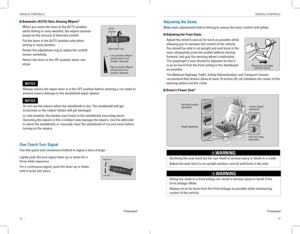
Under the Hood
4-cylinder models
Brake �uid
(black cap)
Engine coolant
reserve tank Radiator cap
Washer �uid
(blue cap) Engine oil dipstick
(orange) Clutch �uid
(light gray cap)
Engine oil �ll cap
Battery
*
6-cylinder model s
Engine oil dipstick
(orange )
Washer �uid
(blue cap)
Engine coolant
reserve tank
Radiator Cap Brake �uid
(black cap)
Engine oil �ll cap
Battery
Clutch �uid
(light gray cap )*
*if equipped
Page 71 of 84

134 || 135
MAINTENANCEMAINTENANCE
Opening the Hood
1. Park the vehicle on a level surface, and set the
parking brake.
2. Pull the hood release handle under the lower left
corner of the dashboard.
3. Push up the hood latch lever in the center of the
hood to release the lock mechanism, and open
the hood.
Follow the steps below to open and close the
hood based on your engine type.
4-cylinder models
remove the support rod from the clamp using the
grip. Mount the support rod in the hood.
When closing, remove the support rod, and
stow it in the clamp, then gently lower the hood.
remove your hand at a height of approximately
12 inches (30 cm) and let the hood close.
6-cylinder models
Lift the hood up most of the way. The hydraulic
supports lift it up the rest of the way and hold it
up.
When closing, lower it to approximately 12
inches (30 cm), then press down firmly with your
hands.
Do not open the hood when the wiper arms are raised. The hood will strik\
e the
wipers, and may damage either the hood or the wipers.
NOTICE
Hood release handle
Pull
Lever
Support ro d
Grip
Clamp
Engine Oil
Park the vehicle on level ground, and wait approximately three minutes after turning
the engine off before you check the oil.
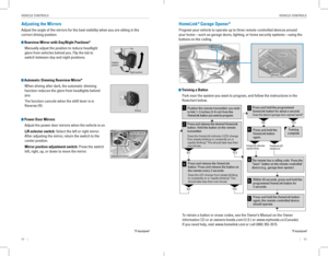
Checking the Oil
1. remove the dipstick (orange).
2. Wipe the dipstick with a clean cloth or paper
towel.
3. Insert the dipstick back all the way into its hole.
4. remove the dipstick again, and check the level.
It should be between the upper and lower marks.
Add oil if necessary.
4-cylinder models
4-cylinder models
Upper mark
Lower mark
6-cylinder models
Upper mark
Lower mark
6-cylinder models
Page 72 of 84

136 || 137
MAINTENANCEMAINTENANCE
Recommended Engine Oil
• Honda Genuine Motor Oil
• Premium-grade 0W-20 detergent oil with an API Certification Seal on the
container
This seal indicates the oil is energy conserving and
that it meets the American Petroleum Institute’s
latest requirements.
Use Honda Genuine Motor oil or another
commercial engine oil of suitable viscosity for the
ambient temperature as shown.
You may also use synthetic motor oil if it is labeled
with the API Certification Seal and is of the
specified viscosity grade.
Do not fill the engine oil above the upper mark. Overfilling the engine oil can result
in leaks and engine damage.
NOTICE
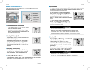
Adding Oil
1. Unscrew and remove the engine oil fill cap.
2. Add oil slowly.
3. reinstall the engine oil fill cap, and tighten it
securely.
4. Wait for three minutes and recheck the engine oil
dipstick.
Ambient temperature
4-cylinder models
Engine oil �ll cap
6-cylinder models
Engine oil �ll cap
Resetting the Engine Oil Life
If you change or replace the vehicle’s engine oil yourself, you must reset the
engine oil life.
Models with information display
1. Press the select/reset knob until the engine oil
life appears in the display.
2. Press and hold the knob for 10 seconds or more,
until the display begins to blink.
3. Press and hold the knob for 5 seconds or more.
The engine oil life display returns to 100%.
Models with multi-information display
Use the Info (p/q) and SEL/RESET buttons on the steering wheel buttons to
control the display.
1. Scroll to the vehicle Settings screen, and select
it.
2. Scroll to the Maintenance reset screen, and
select it.
3. Select reset. The maintenance codes disappear,
and the engine oil life display returns to 100%.
Failure to reset the Maintenance Minder™ display after a maintenance \
service
results in the system showing incorrect maintenance intervals, which can\
lead to
serious mechanical problems.
NOTICE