2016 FORD SUPER DUTY warning light
[x] Cancel search: warning lightPage 178 of 510
PRINCIPLE OF OPERATION
WARNINGS
Hill descent control cannot control
descent in all surface conditions and
circumstances, such as ice or
extremely steep grades. Hill descent
control is a driver assist system and cannot
substitute for good judgment by the driver.
Failure to do so may result in loss of vehicle
control, crash or serious injury. Hill descent control does not provide
hill hold at zero miles per hour (0
kilometers per hour). When stopped,
the parking brake must be applied or the
vehicle must be placed in P (Park) or it
may roll away. Hill descent control allows the driver to set
and maintain vehicle speed while
descending steep grades in various surface
conditions.
Hill descent control can maintain vehicle
speeds on downhill grades between 2 mph
(3 km/h) and 12 mph (20 km/h). Above 20
mph (32 km/h), the system remains
armed, but descent speed cannot be set
or maintained.
Hill descent control requires a cooling
down interval after a period of sustained
use. The amount of time that the feature
can remain active before cooling varies
with conditions. The system will provide a
warning in the message center and a chime
will sound when the system is about to
disengage for cooling. At this time,
manually apply the brakes as needed to
maintain descent speed. USING HILL DESCENT
CONTROL Press and release the hill
descent button located on the
instrument panel. A light in the
cluster will illuminate and a chime will
sound when this feature is activated.
To increase descent speed, press the
accelerator pedal until the desired speed
is reached. To decrease descent speed,
press the brake pedal until the desired
speed is reached.
Whether accelerating or decelerating, once
the desired descent speed is reached,
remove your feet from the pedals and the
chosen vehicle speed will be maintained.
Note: Noise from the ABS pump motor may
be observed during hill descent control
operation. This is a normal characteristic of
the ABS and should be no reason for
concern.
Hill descent modes
• At speeds below 20 mph (32 km/h):
When the Hill Descent Control switch
is pressed and Hill Descent Control is
active, the Hill Descent Control telltale
will flash.
• At speeds below 20 mph (32 km/h):
When the Hill Descent Control switch
is pressed and conditions are not
correct for hill descent activation, the
Hill Descent Control system will be
enabled, the Hill Descent Control
telltale will be solid and a message will
display in the information display.
• At speeds above 20 mph (32 km/h):
When the Hill Descent Control switch
is pressed, the Hill Descent Control
system will be enabled, the telltale in
the cluster will not be illuminated and
a message will be displayed in the
information display.
175
Super Duty (TFA) Canada/United States of America, enUSA, Second Printing Terrain Response
(If Equipped)E163957
Page 180 of 510
PARKING AID (If Equipped)
WARNINGS
The system does not relieve you of
your responsibility to drive with due
care and attention.
If your vehicles has a non-Ford
approved trailer tow module the
system may not correctly detect
objects. The sensors may not detect objects
in heavy rain or other conditions that
cause disruptive reflections.
The sensors may not detect objects
with surfaces that absorb ultrasonic
waves.
The system does not detect objects
that are moving away from your
vehicle. They will only be detected
shortly after they start to move toward
your vehicle. Take particular care when reversing
with a tow ball arm or a rear fitted
accessory. For example, a bicycle
carrier. The rear parking aid will only
indicate the approximate distance from
the rear bumper to an object. Note:
If you use a high pressure spray to
wash your vehicle, only spray the sensors
briefly from a distance not less than
8 in
(20 cm).
Note: If your vehicle has a tow ball arm, the
system is turned off automatically when
trailer lamps (or lighting boards) are
connected to the 13-pin socket through a
Ford approved trailer tow module.
Note: Keep the sensors free from dirt, ice
or snow. Do not clean with sharp objects.
Note: The system may emit false alerts if
it detects a signal using the same frequency
as the sensors or if your vehicle is fully
loaded. Note:
The outer sensors may detect the
side walls of a garage. If the distance
between the outer sensors and the side wall
remains constant for three seconds, the
alert will turn off. As you continue the inner
sensors will detect objects directly behind
your vehicle.
Rear Parking Aid
The rear sensors are only active when the
transmission is in reverse (R). As your
vehicle moves closer to the obstacle, the
rate of the audible warning increases.
When the obstacle is less than
10 in
(25 cm) away, the warning sounds
continuously. If the system detects a
stationary or receding object farther than
10 in (25 cm)
from the corners of the
bumper, the tone sounds for only three
seconds. Once the system detects an
object approaching, the warning sounds
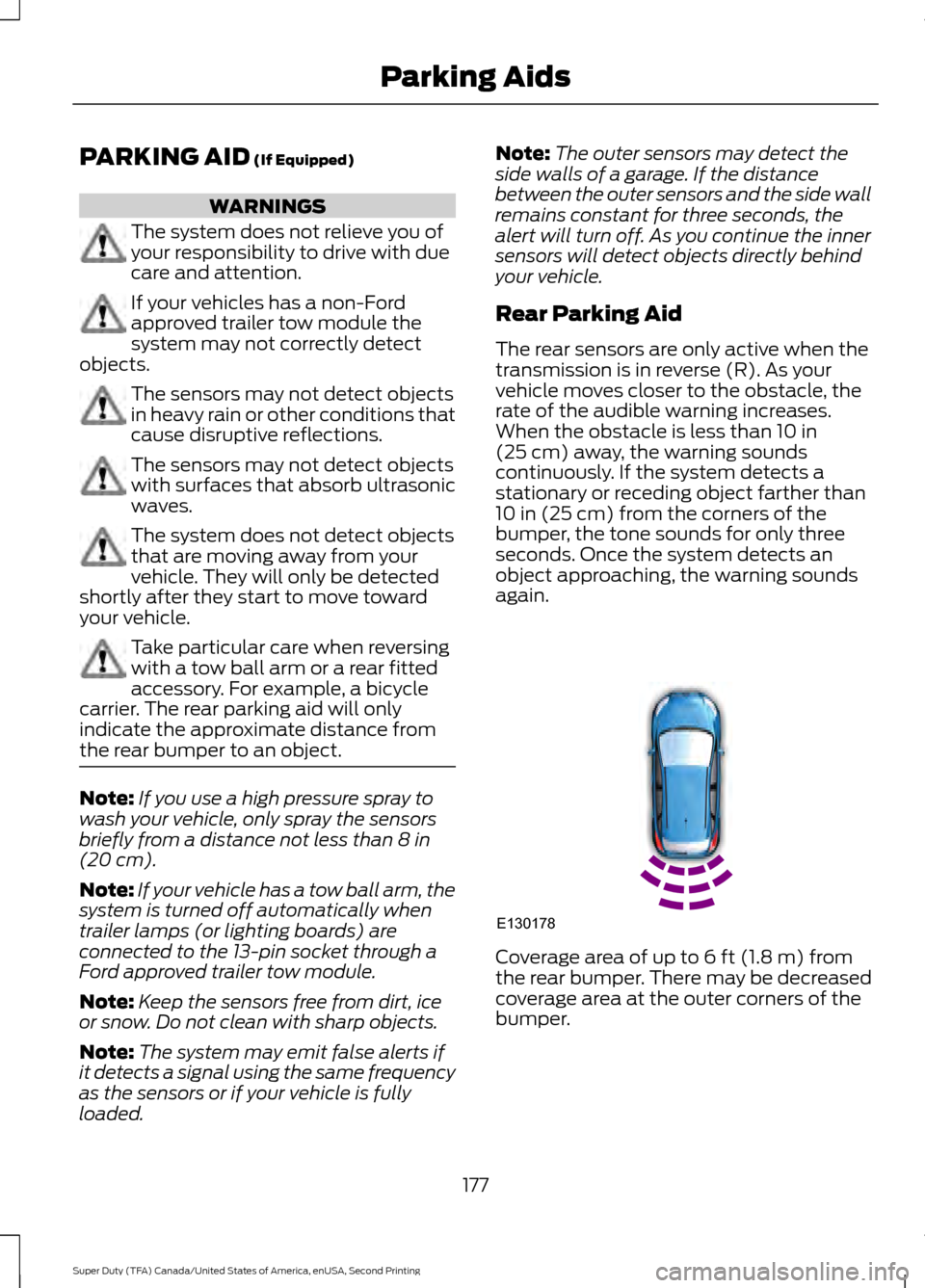
again. Coverage area of up to
6 ft (1.8 m) from
the rear bumper. There may be decreased
coverage area at the outer corners of the
bumper.
177
Super Duty (TFA) Canada/United States of America, enUSA, Second Printing Parking AidsE130178
Page 193 of 510
TOWING A TRAILER
WARNINGS
Do not exceed the GVWR or
the GAWR specified on the
certification label. Towing trailers beyond the
maximum recommended
gross trailer weight exceeds the
limit of the vehicle and could
result in engine damage,
transmission damage, structural
damage, loss of vehicle control,
vehicle rollover and personal
injury. Your vehicle may have electrical
items, such as fuses or relays,
related to towing. See Fuses
(page 223).
Your vehicle's load capacity
designation is by weight, not by
volume, so you cannot necessarily
use all available space when
loading a vehicle or trailer.
Towing a trailer places an extra
load on your vehicle's engine,
transmission, axle, brakes, tires
and suspension. Inspect these
components periodically during,
and after, any towing operation. Load Placement
To help minimize how trailer
movement affects your vehicle
when driving:
•
Load the heaviest items closest
to the trailer floor.
• Load the heaviest items
centered between the left and
right side trailer tires.
• Load the heaviest items above
the trailer axles or just slightly
forward toward the trailer
tongue. Do not allow the final
trailer tongue weight to go
above or below 10-15% of the
loaded trailer weight.
• Select a ball mount with the
correct rise or drop. When both
the loaded vehicle and trailer
are connected, the trailer frame
should be level, or slightly
angled down toward your
vehicle, when viewed from the
side.
When driving with a trailer or
payload, a slight takeoff vibration
or shudder may be present due to
the increased payload weight.
Additional information regarding
proper trailer loading and setting
your vehicle up for towing is
located in another chapter of this
manual. See
Load Limit (page
183).
You can also find information in
the
RV & Trailer Towing Guide
available at your authorized
dealer, or online.
190
Super Duty (TFA) Canada/United States of America, enUSA, Second Printing Towing
Page 194 of 510
RV & Trailer Towing Guide Online
http://www.fleet.ford.com/towing-guides/
Website
TRAILER SWAY CONTROL (If
Equipped) WARNING
Turning off trailer sway control
increases the risk of loss of vehicle
control, serious injury or death. Ford
does not recommend disabling this feature
except in situations where speed reduction
may be detrimental (such as hill climbing),
the driver has significant trailer towing
experience, and can control trailer sway
and maintain safe operation. Note:
This feature does not prevent trailer
sway, but reduces it once it begins.
Note: This feature cannot stop all trailers
from swaying.
Note: In some cases, if vehicle speed is too
high, the system may activate multiple
times, gradually reducing vehicle speed.
This feature applies your vehicle brakes at
individual wheels and, if necessary, reduces
engine power. If the trailer begins to sway,
the stability control light flashes and the
message
TRAILER SWAY REDUCE
SPEED appears in the information display.
The first thing to do is slow your vehicle
down, then pull safely to the side of the
road and check for proper tongue load and
trailer load distribution. See
Load
Carrying (page 183). RECOMMENDED TOWING
WEIGHTS
Note:
Make sure to take into
consideration trailer frontal area.
Do not exceed 60 feet 2
(5.6
meters 2
) trailer frontal area for
conventional trailers. Do not
exceed 75 feet 2
(6.9 meters 2
) trailer
frontal area for 5th wheel and
gooseneck trailers.
Note: Exceeding this limitation
may significantly reduce the
performance of your towing
vehicle. Selecting a trailer with a
low aerodynamic drag and rounded
front design helps optimize
performance and fuel economy.
Note: For high altitude operation,
reduce the gross combined weight
by 2% per 1000 feet (300 meters)
starting at the 1000 foot (300
meter) elevation point.
Note: Certain states require
electric trailer brakes for trailers
over a specified weight. Be sure to
check state regulations for this
specified weight. The maximum
trailer weights listed may be limited
to this specified weight, as your
vehicle's electrical system may not
include the wiring connector
needed to use electric trailer
brakes.
191
Super Duty (TFA) Canada/United States of America, enUSA, Second Printing Towing
Page 200 of 510
When hooking-up a trailer using a
weight-distributing hitch, always use the
following procedure:
1. Park the loaded vehicle, without the
trailer, on a level surface.
2. Measure the height to the top of your vehicle's front wheel opening on the
fender. This is H1.
3. Attach the loaded trailer to your vehicle
without the weight-distributing bars
connected.
4. Measure the height to the top of your vehicle's front wheel opening on the
fender a second time. This is H2.
5. Install and adjust the tension in the weight-distributing bars so that the
height of your vehicle's front wheel
opening on the fender is approximately
halfway between H1 and H2.
6. Check that the trailer is level or slightly
nose down toward your vehicle. If not,
adjust the ball height accordingly and
repeat Steps 2-6.
Once the trailer is level or slightly nose
down toward the vehicle:
• Lock the bar tension adjuster in place.
• Check that the trailer tongue securely
attaches and locks onto the hitch.
• Install safety chains, lighting, and trailer
brake controls as required by law or the
trailer manufacturer. Fifth-wheel Trailer Hitch (If Equipped) WARNING
The mounting pads in the bed are
specifically designed for certain
fifth-wheel trailer hitches and
gooseneck ball hitches. Do not use these
mounting pads for other purposes. Doing
so could result in vehicle structural
damage, loss of vehicle control, and
personal injury. Contact an authorized
dealer to purchase gooseneck and
fifth-wheel hitches that are compatible
with your vehicle. Your vehicle may be equipped with a
fifth-wheel prep package. This package
enables your vehicle to accept certain
fifth-wheel trailer hitches and gooseneck
ball hitches. The fifth-wheel trailer hitch
attaches to the four mounting pads in the
pick-up bed. An optional 7-pin trailer wiring
connector may be in the bed as well. The
gooseneck ball hitch is a separate
mounting pad from the fifth-wheel hitch,
located in the center of the bed.
Shorter pick-up boxes, such as the 6½-foot
box on the F-250 and F-350, provide less
clearance between the cab and the
fifth-wheel and gooseneck trailer
compared to longer box pick-ups, such as
an 8-foot box on the F-250 or F-350. When
selecting a trailer and tow vehicle, it is
critical to check that this combination
provides clearance between the front of
the trailer and tow vehicle for turns up to
90 degrees. Failure to follow this
recommendation could result in the trailer
contacting the cab of the tow vehicle
during tight turns that are typical during
low-speed parking and turning maneuvers.
This contact could result in damage to the
trailer and tow vehicle.
197
Super Duty (TFA) Canada/United States of America, enUSA, Second Printing Towing
Page 204 of 510
•
The controller interacts with the brake
control system and powertrain control
system of your vehicle to provide the
best performance on different road
conditions.
• Your vehicle's brake system and the
trailer brake system work
independently of each other. Changing
the gain setting on the controller does
not affect the operation of your
vehicle's brakes.
• When you switch the engine off, the
controller output is disabled and the
display and module shut down.
Trailer Lamps WARNING
Never connect any trailer lamp wiring
to the vehicle's tail lamp wiring; this
may damage the electrical system
resulting in fire. Contact your authorized
dealer as soon as possible for assistance
in proper trailer tow wiring installation.
Additional electrical equipment may be
required. Trailer lamps are required on most towed
vehicles. Make sure all running lights, brake
lights, turn signals and hazard lights are
working.
Before Towing a Trailer
Practice turning, stopping and backing up
to get the feel of your vehicle-trailer
combination before starting on a trip.
When turning, make wider turns so the
trailer wheels clear curbs and other
obstacles.
When Towing a Trailer
•
Do not drive faster than 70 mph
(113 km/h) during the first 500 mi
(800 km).
• Do not make full-throttle starts. •
Check your hitch, electrical connections
and trailer wheel lug nuts thoroughly
after you have traveled 50 mi (80 km).
• When stopped in congested or heavy
traffic during hot weather, place the
gearshift in position P to aid engine and
transmission cooling and to help A/C
performance.
• Turn off the speed control with heavy
loads or in hilly terrain. The speed
control may turn off automatically
when you are towing on long, steep
grades.
• Shift to a lower gear when driving down
a long or steep hill. Do not apply the
brakes continuously, as they may
overheat and become less effective.
• If your transmission is equipped with a
Grade Assist or Tow/Haul feature, use
this feature when towing. This provides
engine braking and helps eliminate
excessive transmission shifting for
optimum fuel economy and
transmission cooling.
• If your vehicle is equipped with
AdvanceTrac with RSC, this system
may turn on during typical cornering
maneuvers with a heavily loaded trailer.
This is normal. Turning the corner at a
slower speed while towing may reduce
this tendency.
• If you are towing a trailer frequently in
hot weather, hilly conditions, at the
gross combined weight rating (or any
combination of these factors), consider
refilling your rear axle with synthetic
gear lubricant (if the axle is not already
filled with it). See
Capacities and
Specifications (page 303).
• Allow more distance for stopping with
a trailer attached. Anticipate stops and
brake gradually.
• Avoid parking on a grade. However, if
you must park on a grade:
201
Super Duty (TFA) Canada/United States of America, enUSA, Second Printing Towing
Page 210 of 510
•
Transmissions give their best fuel
economy when operated in the top
cruise gear and with steady pressure
on the gas pedal.
• Four-wheel-drive operation (if
equipped) is less fuel efficient than
two-wheel-drive operation.
• Close the windows for high-speed
driving.
DRIVING THROUGH WATER WARNING
Do not drive through flowing or deep
water as you may lose control of your
vehicle.
Note:
Driving through standing water can
cause vehicle damage.
Note: Engine damage can occur if water
enters the air filter.
Before driving through standing water,
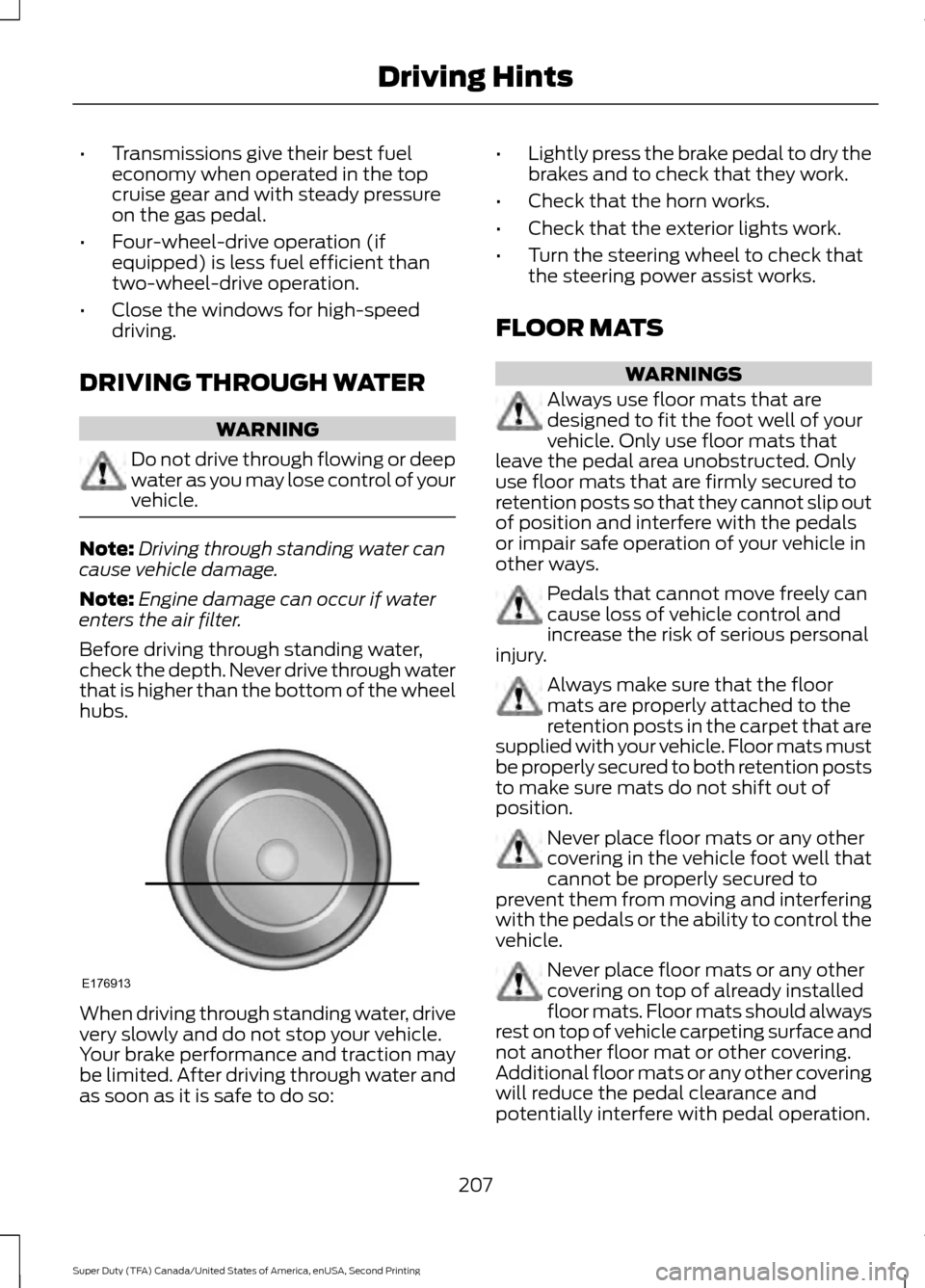
check the depth. Never drive through water
that is higher than the bottom of the wheel
hubs. When driving through standing water, drive
very slowly and do not stop your vehicle.
Your brake performance and traction may
be limited. After driving through water and
as soon as it is safe to do so: •
Lightly press the brake pedal to dry the
brakes and to check that they work.
• Check that the horn works.
• Check that the exterior lights work.
• Turn the steering wheel to check that
the steering power assist works.
FLOOR MATS WARNINGS
Always use floor mats that are
designed to fit the foot well of your
vehicle. Only use floor mats that
leave the pedal area unobstructed. Only
use floor mats that are firmly secured to
retention posts so that they cannot slip out
of position and interfere with the pedals
or impair safe operation of your vehicle in
other ways. Pedals that cannot move freely can
cause loss of vehicle control and
increase the risk of serious personal
injury. Always make sure that the floor
mats are properly attached to the
retention posts in the carpet that are
supplied with your vehicle. Floor mats must
be properly secured to both retention posts
to make sure mats do not shift out of
position. Never place floor mats or any other
covering in the vehicle foot well that
cannot be properly secured to
prevent them from moving and interfering
with the pedals or the ability to control the
vehicle. Never place floor mats or any other
covering on top of already installed
floor mats. Floor mats should always
rest on top of vehicle carpeting surface and
not another floor mat or other covering.
Additional floor mats or any other covering
will reduce the pedal clearance and
potentially interfere with pedal operation.
207
Super Duty (TFA) Canada/United States of America, enUSA, Second Printing Driving HintsE176913
Page 211 of 510
WARNINGS
Check attachment of floor mats on
a regular basis. Always properly
reinstall and secure floor mats that
have been removed for cleaning or
replacement. Always make sure that objects
cannot fall into the driver foot well
while the vehicle is moving. Objects
that are loose can become trapped under
the pedals causing a loss of vehicle control. Failure to properly follow floor mat
installation or attachment
instructions can potentially cause
interference with pedal operation causing
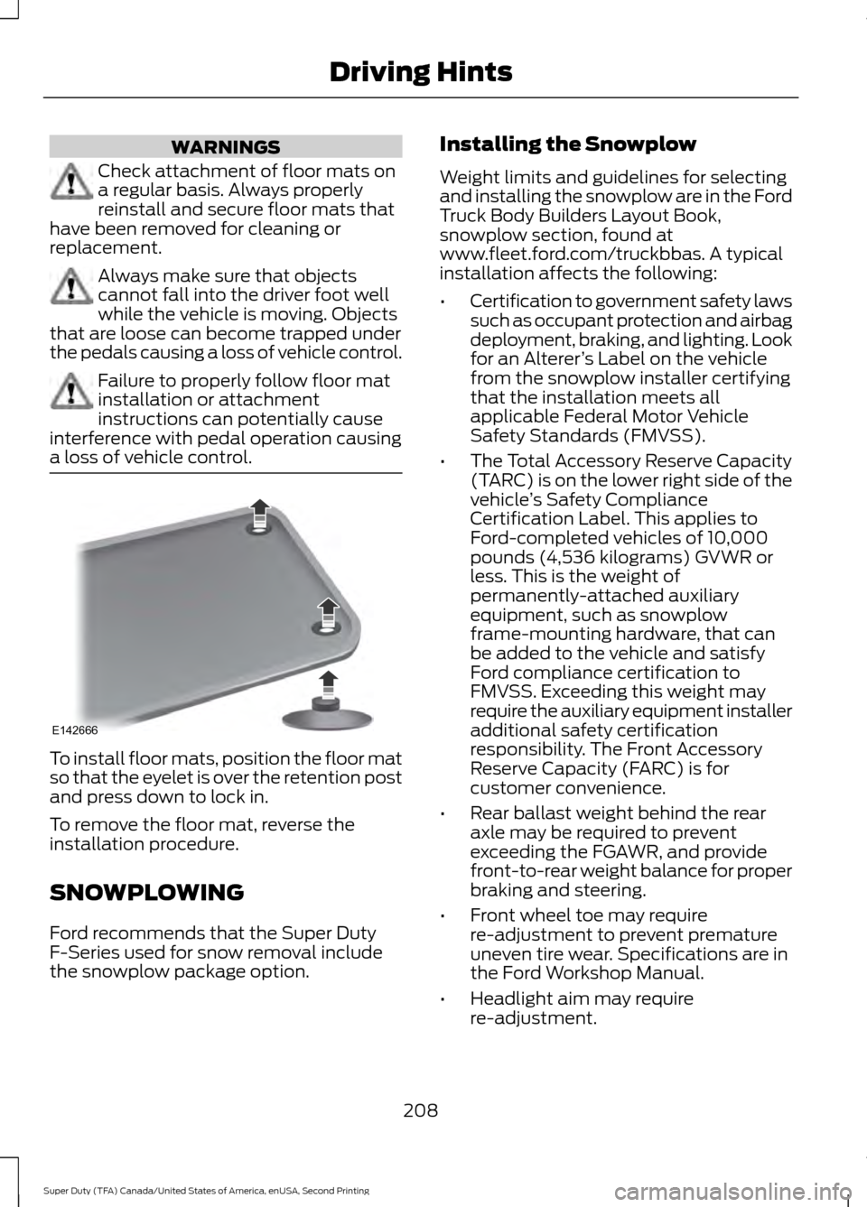
a loss of vehicle control. To install floor mats, position the floor mat
so that the eyelet is over the retention post
and press down to lock in.
To remove the floor mat, reverse the
installation procedure.
SNOWPLOWING
Ford recommends that the Super Duty
F-Series used for snow removal include
the snowplow package option. Installing the Snowplow
Weight limits and guidelines for selecting
and installing the snowplow are in the Ford
Truck Body Builders Layout Book,
snowplow section, found at
www.fleet.ford.com/truckbbas. A typical
installation affects the following:
•
Certification to government safety laws
such as occupant protection and airbag
deployment, braking, and lighting. Look
for an Alterer ’s Label on the vehicle
from the snowplow installer certifying
that the installation meets all
applicable Federal Motor Vehicle
Safety Standards (FMVSS).
• The Total Accessory Reserve Capacity
(TARC) is on the lower right side of the
vehicle ’s Safety Compliance
Certification Label. This applies to
Ford-completed vehicles of 10,000
pounds (4,536 kilograms) GVWR or
less. This is the weight of
permanently-attached auxiliary
equipment, such as snowplow
frame-mounting hardware, that can
be added to the vehicle and satisfy
Ford compliance certification to
FMVSS. Exceeding this weight may
require the auxiliary equipment installer
additional safety certification
responsibility. The Front Accessory
Reserve Capacity (FARC) is for
customer convenience.
• Rear ballast weight behind the rear
axle may be required to prevent
exceeding the FGAWR, and provide
front-to-rear weight balance for proper
braking and steering.
• Front wheel toe may require
re-adjustment to prevent premature
uneven tire wear. Specifications are in
the Ford Workshop Manual.
• Headlight aim may require
re-adjustment.
208
Super Duty (TFA) Canada/United States of America, enUSA, Second Printing Driving HintsE142666